
Design a Robotic Mechanism - Component of Low and
Non-pollution Manufacturing Systems
Decoupling Movement of a Robotic Mechanism with Three Degrees
of Freedom, using Couplings and Wires Transmission
Nicolae Bercan
1
, Mihaiela Iliescu
2
and Cristian Matran
1
1
Lucian Blaga University, 10 Victoriei Street, Sibiu, Romania
2
Institute of Solid Mechanics, Romanian Academy, 15 Constantin Mille Street, Bucharest, Romania
Keywords: Robotic Mechanism, Coupling, Wires Transmission.
Abstract: The growing presence of industrial robots in low and non-pollution manufacturing systems requires the
development of a database. This paper presents a form of robotic mechanism with three degrees of freedom,
driven by wires and pulley wheels. It is necessary to present this type of mechanisms, because the literature
data in the field of robotic mechanisms operated through wires are, relatively, poor. It is presented a structural
and kinematic analysis of a robotic mechanism guidance, establishing equations of motion (e.g. for speeds,
moments).
1 INTRODUCTION
The mechanism studied in the paper is derived from
a robotic mechanism with gears and represents one
important component of a (data) base of mechanisms
with wires and pulley wheels, used in designing
robotic mechanisms.
The solution of replacing the serrated wheels with
equivalent mechanisms with pulley wheels and wires
is rational and economical – with the assumptions of
dealing with small and medium loads.
These mechanisms are used particularly in the
nuclear industry, medicine, etc. (Coiffet, 1993),
(Vertut, 2012) when low, or non-pollution
manufacturing systems are involved.
2 NOTATION AND SYMBOLS
The notation and symbols used in this paper are
mentioned next
M - represents the mobility grade of the
mechanisms;
M
I
, M
II
, ...- mobility grade of each of the
component mechanisms;
L
C
- number of couplings between the
mechanisms;
a
- angular velocity of the “a” element relative
to the base;
C- coupling grade of the motions;
M
a
- the moment of the element “a”;
a
()
=
a
(
0;
0).
i
c
ab
- transmission ratio from the element “a”
to the element “b”, when the angular velocity
c
= 0; (Dudita, 1984).
3 STRUCTURE AND KINEMATIC
ANALYSES OF THE ROBOTIC
MECHANISM
3.1 Structural Analysis of the Robotic
Mechanism
The authors present a version of decoupling the
movements by couplings, for a robotic-mechanism
whose movement transmission is provided by wires.
There have been done, both, structural and
kinematic analyses for the orientation mechanism I and
the decoupling movements of mechanism II.
Consequently, there were determined the overall
functions of transmission gears and moments, as well
as the conditions of release movements (see figure 1).
Bercan, N., Iliescu, M. and Matran, C.
Design a Robotic Mechanism - Component of Low and Non-pollution Manufacturing Systems - Decoupling Movement of a Robotic Mechanism with Three Degrees of Freedom, using
Couplings and Wires Transmission.
In Proceedings of the 5th International Conference on Smart Cities and Green ICT Systems (SMARTGREENS 2016), pages 443-447
ISBN: 978-989-758-184-7
Copyright
c
2016 by SCITEPRESS – Science and Technology Publications, Lda. All rights reserved
443
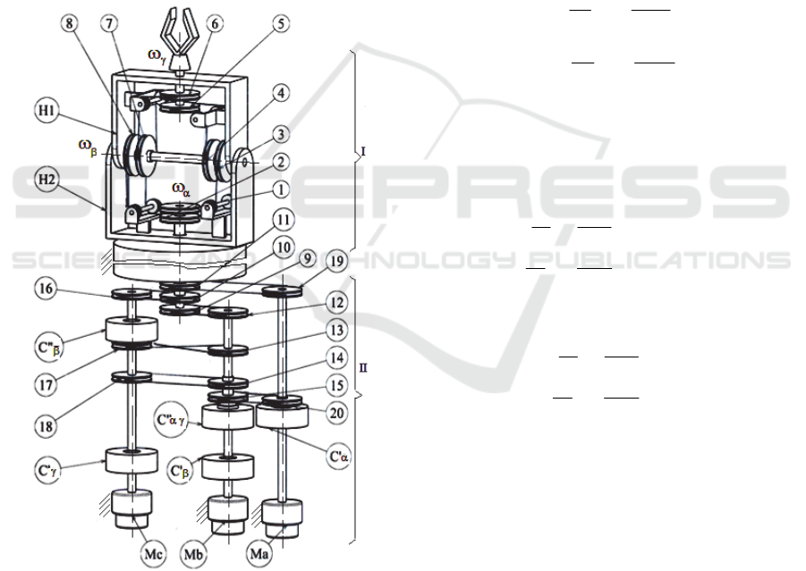
In terms of kinematic and structural analysis, the
proper guidance of mechanism, driven by wires through
single or double pulley wheels, it has been extensively
analysed by the analytical method (Bercan, 2004).
The robotic-mechanism of orientation I, is formed
by combining the cinematic chain bi-mobile open A =
(0 - H1 - H2) with three mono-mobile mechanisms with
wires B = (1 - 3 - H2), C = (2 - 8 - H2) and D =
(4 - 5 = 6 - 7 - H1). The mobility grade of the
orientation mechanism is given by relation (1):
M
I
= M
A
+ ... + M
D
- L
C
= 2 + 1 + 1 + 1 - 2 = 3 (1)
Where L
C
= 2 represents the component between the
composing mechanisms (3=4) and (8=7).
The innovative orientation mechanism I, has
L
I
= 6 external connections, three inputs (0-2-H
2
) and
three outputs (, , ).
Figure 1: The robotic mechanism acted by wires.
Because the mechanism is three-mobile, it results
that M
1
= 3, as there are independent motions (
,
,
and L
I
– M
I
= 6 – 3 = 3, as there are dependent
motions (
.
The mechanism has L
I
– M
I
= 3 independent
exterior moments (M
1
, M
2
, M
H2
) and M
I
=3
dependent exterior moments (M
, M
, M
The coupling grade of the proposed orientation
mechanism is:
C = C
+ C
+ C
= (3–1) + (2–1) + (2–1)= 4
(2)
This means that the - motion is coupled with the
motions and , the motion is coupled with the
motion , and the motion is coupled to the motion.
3.2 Kinematical Analysis of the Robotic
Mechanism
In order to establish the transmission functions for
speeds and moments, the authors apply the principle
of superposition of the effects, so that functions (3)
are obtained:
2
72
86
2
8
2
41
53
1
3
1
H
RR
RR
R
R
RR
RR
R
R
(3)
Written in matrix form, they turn into next
functions, given by (4):
001
1
1
;
001
1
1
72
86
2
8
41
53
1
3
72
86
2
8
41
53
1
3
2
1
2
RR
RR
R
R
RR
RR
R
R
Awhere
A
RR
RR
R
R
RR
RR
R
R
H
(4)
With the assumptions of neglecting the abrasion
and the inertia forces, the transmission function of the
moments can be determined using the principle of the
virtual mechanical power, as presented by equation
(5):
2
2
1
H
T
M
M
M
A
M
M
M
(5)
A particular case, with practical application, is
that when the radii of the wheels are equal. So, the
equations (4) and (5) turn into equation (6):
MoMa-GreenSys 2016 - Special Session on Modelling Practical Paradigms of Green Manufacturing Systems
444
001
111
111
1
H
2
1
T
1b
a
1
H
2
1
;;
22
Awhere
M
M
M
A
M
M
M
A
c
(6)
For the decoupling study, it is most convenient
when the transmission functions of the velocity are
expressed by relationship (7):
22
2
1
2
1
1
1
1
2
1
2
1
0
2
1
2
1
100
HH
A
(7)
Kinematics and structural analysis will be done in
particular for the decoupling mechanism II, when for
the simplified calculation is being used general
analytical method.
The decoupling mechanism II is a tri-mobile
mechanism composed from six mono-mobile
mechanisms acted by wires E=(11 19), F=(10 16),
G=(9 12), H=(13 17), I=(14 18) and J=(15 20)
together with five couplings, (C’
α
, C’
β
, C’
γ
, C”
αγ
and
C”
β
). The mechanism is driven by three stepping
motors (Ma, Mb, Mc), (Bercan, 1995), (Bercan,
1999), (Stareţu, 2009).
The coupling degree of the guidance mechanism
is calculated as expressed by equation (8):
C = C
+ C
+ C
= (3 – 1) + (2 – 1) + (2 - 1)= 4
(8)
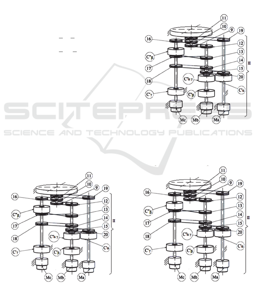
Figure 2: The α movement conditions.
To achieve the α movement, the Ma motor in
running and will be locked by the stepper motor Mb and
Mc (see figure 2).Under these conditions, the couplings
C'α and C"α are coupled and the others are decoupled.
To achieve the β movement, the Mb motor in
running and will be locked by the stepper motor Ma and
Mc (see figure 3). Under these conditions, the couplings
C'
β
and C"
β
are coupled and the others are decoupled.
To achieve the γ movement, the Mc motor in
running and will be locked by the stepper motor Ma and
Mb (see figure 4). Under these conditions, the couplings
C'γ and C"γ are coupled and the others are decoupled.
Figure 3: The β movement conditions.
To determine the decoupling conditions of the
oriented movements, there is proceeded like in
previous cases, so that there are obtained the
following transmission ratios equals:
Figure 4: The γ movement conditions.
Design a Robotic Mechanism - Component of Low and Non-pollution Manufacturing Systems - Decoupling Movement of a Robotic
Mechanism with Three Degrees of Freedom, using Couplings and Wires Transmission
445

for decoupling movements γ - β:
R
R
=
i
=
i
RR
RR
=
ii
=
i
:where
;
i
=
i
10
16
16-10c-10
149
1812
18-1412-9
c-9
c-10c-9
(9)
for decoupling movements β - γ:
RR
RR
- =
ii
=
i
R
R
=
i
=
i
:where
;
i
- =
i
1710
1316
13-1716-10b-10
9
12
12-9b-9
b-10b-9
(10)
for decoupling movements α – (β and γ) (see
equation 11)
From relations (9), (10) and (11) we obtain the
conditions for decoupling, given by equation (12).
R
R
=
i
=
i
RRR
RRR
=
iii
=
i
RR
RR
=
ii
=
i
:where
;
i
=
i
=
i
11
19
19-11a-11
151810
201416
30-1514-1816-10a-10
159
2012
22-1512-9a-9
a-9a-10a-11
;
;
(11)
RRR
RRR
=
R
R
RR
RR
=
R
R
RR
RR
=
R
R
151810
201416
11
19
1710
1316
9
12
149
1812
10
16
(12)
These relationships are fulfilled in the particular
case of equal radii: R
9
= ... =R
20
.
For the robotic mechanism with decoupled
movements (see figure 1), we obtain the functions of
velocity transmission, as follows:
1
0
for ω
β
=0 and ω
γ
=0 =>ω
b
=0 and ω
c
=0
R
R
=
R
R
=
i
=
i
: where;
i
=
11
19
a
11
19
19-11a-a-a
(13)
2
0
for ω
α
=0 and ω
γ
=>ω
a
=0 and ω
c
=0
RRR
RRR
- =
RRR
RRR
- =
iii
=
i
: where
;
i
=
1710
16132
b
1710
13162
13-1716-102-b-
b-b
8
8
8
(14)
3
0
for ω
α
=0 and ω
β
=0 =>ω
a
=0 and ω
b
=0
RRR
RRR
- =
RRR
RRR
- =
iii
=
i
:where
i
=
1086
1672
c
10
1627
16-102-7-c-
c-c
86
86
(15)
The velocities functions of overall transmission
for the robotic mechanism with decoupled
movements are expressed by the matrix form
presented in equation (16):
c
b
a
10
1627
1710
13162
11
19
RRR
RRR
-
00
0
RRR
RRR
-
0
00
R
R
=
86
8
(16)
In the case of equal values for radii, the
relationship (16) turns into (17):
c
b
a
1-00
01-0
001
=
(17)
Under the assumptions of neglecting the abrasion
and the inertia forces, the transmission function of the
moments can be expressed by equation (18).
M
M
M
100
010
001-
=
M
M
M
c
b
a
(18)
4 CONCLUSIONS
The mechanism studied in this paper is derived from
a robotic-mechanism with gears and represents one
MoMa-GreenSys 2016 - Special Session on Modelling Practical Paradigms of Green Manufacturing Systems
446

important component of a (data) base of mechanisms
with wires and pulley wheels, used in designing
robotic mechanisms.
The solution of replacing the serrated wheels with
equivalent mechanisms with pulley wheels and wires
is rational and economical under the circumstances of
dealing with little and medium charges. This type of
mechanisms, beyond being silent and with good
maintenance, do not need lubricants while working
and do not develop thermal energy.
This solution is also relevant for industrial robots
in low and non-pollution manufacturing systems
(Iliescu, 2015).
The determined transmission functions are
applied in programming the robotic-mechanisms, as
well as in their design calculi. They are also used in
the studies of mechanical decoupling for orientation
movement.
Further development of this study aims the
analysis of the mechanism from the kinematical and
dynamic points of view of, as well as the fatigue
behaviour by computer aided programs, CAD
software.
REFERENCES
Coiffet Ph., 1993. Robot Sapiens, Robot Habilis. Editura
Hermes. Paris.
Vertut, J., 2012. Teleoperation and robotics: Applications
and technology, Paris. ISBN-13: 9789401161053.
Dudita, Fl., Diaconescu, D., 1984. Curs mecanisme -
fascicula 3, Cinematica mecanismelor cu roti dintate.
Litografia Universitatii "Transilvania" din Brasov.
Bercan, N., 2004. The Structural And Kinematic Analyse
For A Trimobil Orienting Robotomechanism Moved
By Tendons With Decouple Motions. In High
Technical Mechanical School - 4 th International
Conference RaDMI “Research And Development In
Mechanical Industry”, CD ISBN 86-83803-18-X,
Volume 2 -ISBN 86-83803-17-1. Zlatibor, Serbia and
Montenegro.
Bercan, N., Diaconescu D., 1995. Mecanisme cu fire pentru
roboti industriali. Editura Universitatii "Lucian Blaga"
din Sibiu.
Bercan, N., 1999. Robotomecanisme cu fire. Baze teoretice.
Editura Universitatii "Lucian Blaga" din Sibiu.
Stareţu, I., 2009. Prehensoare antropomorfe cu bare
articulate sau cu fire şi role pentru roboţi industriali –
Sinteză, analiză şi proiectare constructivă. In Buletinul
AGIR nr. 1/2009.
Iliescu, M., Spirleanu, C., Bercan, N. and Vladareanu, L.,
2015. Flexible Robotic Cell for Optimization of
Grinding Process for 40C130 Metallized Coating. In
Academic Journal of Manufacturing Engineering,
vol. 13, ISSUE 2/2015, pag. 30-35, ISSN: 15837904.
Design a Robotic Mechanism - Component of Low and Non-pollution Manufacturing Systems - Decoupling Movement of a Robotic
Mechanism with Three Degrees of Freedom, using Couplings and Wires Transmission
447
