
Modeling and Executing Component-based Applications in C-Forge
Francisca Rosique, Diego Alonso, Juan Pastor and Francisco Ortiz
Division of Systems and Electronic Engineering (DSIE), Universidad Polit
´
ecnica de Cartagena,
Campus Muralla del Mar, E-30202, Cartagena, Spain
Keywords:
Software Engineering, Component-based Software Development, Model-driven Software Development,
Framework, Software Design Patterns, Real-time.
Abstract:
This paper describes a model-driven toolchain for developing component-based applications that enables users
to use the same models that define their application to execute them. In this vein, models always remain true
to the final application, unlike other approaches where a model tranformation generates a skeleton of the final
application after the first steps of the development process. These kind of approaches normally end up with
models that represent a different application than the one present in the code.
1 INTRODUCTION AND
MOTIVATION
The Component Based Software Engineering
(CBSE) (Crnkovic, 2011) paradigm promotes the
encapsulation of proven solutions into reusable
building blocks, considering components as some-
thing beyond a compiled module or library. CBSE
approaches should consider concerns beyond purely
structure/behavior modeling, such as component
execution, configuration, deployment, analysis,
etc. The Model-Driven Software Development
(MDSD) (Schmidt, 2006) paradigm can help design-
ing development processes for CBSE applications
that take into account all these concerns, allowing
users to concentrate on domain concepts rather
than in code or configuration parameters. Model
transformations (Malavolta, 2010) complement the
approach by providing the means to automatically
generate other representations, either in the form of
models or text (source code).
Generally, model-driven processes for developing
component-based (CB) applications only use models
on the first steps of the project. Afterwards, a set
of model transformations generate the code skeletons
where the user fills-in the code and then the applica-
tion is compiled. The problem with this approach is
that when the user must make a change, he/she forgets
about the original models of the application and now
the user makes all the modifications directly on the
code. But not all kind of changes should be made at
the code level. For instance, if the application needs
a new component, this component should be added at
the model level and then the code should be regener-
ated in order to keep it true to the model. Otherwise,
the model and the code end representing different ap-
plications. And this is an important problem not only
in CBSE but in many other domains.
One of the possible solutions to this problem is
to really have a model-driven process, from the be-
ginning to the end, where all the involved software
artefacts are either models themselves, or are aware
of the presence of models and use them consistently
and coherently. The goal of such a process would be
to be able to use the same CB models that describe the
application to execute it. In any case, code is neces-
sary, but we should try to use models as long as possi-
ble. This paper describes how we have implemented
these ideas in the context of the C-Forge toolchain. C-
Forge is a development process for CBSE supported
by a MDSD toolchain developed in the Eclipse IDE
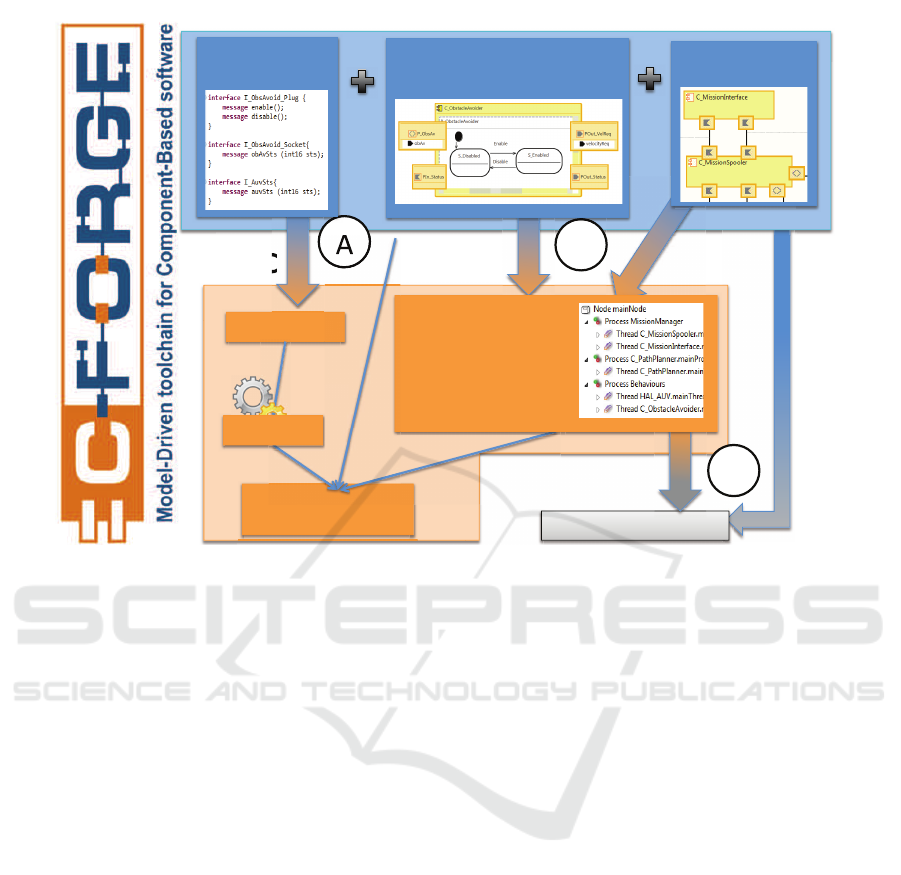
that is composed of three parts, shown in Fig. 1:
• WCOMM tool: provides two graphical editors
and a textual one for modeling the structure and
behavior of CB applications from a platform in-
dependent point of view.
• FraCC tool: provides a model loader, a deploy-
ment metamodel and a compiled C
++
framework.
The framework provides the run-time support re-
quired for executing WCOMM models with dif-
ferent deployment configurations (distribution of
components to nodes and processes, and assign-
ment of computational load to threads). FraCC
also includes a model loader that instantiates the
Rosique, F., Alonso, D., Pastor, J. and Ortiz, F.
Modeling and Executing Component-based Applications in C-Forge.
DOI: 10.5220/0005905701030108
In Proceedings of the 11th International Joint Conference on Software Technologies (ICSOFT 2016) - Volume 1: ICSOFT-EA, pages 103-108
ISBN: 978-989-758-194-6
Copyright
c
2016 by SCITEPRESS – Science and Technology Publications, Lda. All rights reserved
103
!"#$$%
!""#$%&'#()*&#
&'(""%
!+&**,'#,-,./%0%#1)*&.#
$)*+,%,)(*+'-%
,22.0(,3)-#&4&($3)-#
()120.&#
)*+
,
,)(*
5#
6#
!#
$+..(/+.%0%
1234567%.8+,,.%
#
#
#
#
#
#
")9:);+;6.%<568%
=;56+%.6(6+>9(285;+%
#
#
#
#
#
#
#
1'2856+26?'+%
#
#
#
#
#
#
@+:,)79+;6%9)*+,-%#
,%%07-1&-8#)9#'&70)-%#
8)#8+'&,*%:#2')(&%%&%#
,-*#-)*&%#
#
#
;%)#.0<','0&%#
*&
2
0.&#
-
%
*+'
*+'
-
Figure 1: The C-Forge development process comprises two tools (WCOMM and FraCC) and three model-transformations.
application from the WCOMM model and a de-
ployment model (described in the following item).
We said FraCC “executes” WCOMM models be-
cause, unlike other approaches, we do not gener-
ate implementation code. FraCC is already com-
piled and provides a model loader that parses
WCOMM models and instantiates FraCC classes
accordingly. It is not an interpreter, since C
++
code is executed at runtime, and thus, the per-
formance of the final application is not affected.
More details about FraCC’s design are provided
in (Alonso, 2014).
• Three model transformations that generate the
rest of the software artifacts required in differ-
ent steps of the C-Forge development process.
Model transformation (A) generates the C
++
code
skeletons where the user must add the application-
specific code. The user code is then compiled into
a dynamic library and loaded by the model loader.
Model transformation (B) generates a deployment
model, which describes how the application is ex-
ecuted by FraCC. Model transformation (C) ex-
ploits the information contained in the WCOMM
and deployment models to generate an analysis
file for performing a schedulability analysis with
Cheddar, so that the user can check whether the
final application will meet its real-time require-
ments.
A detailed description of C-Forge and its appli-
cation in the context of an autonomous underwater
vehicle, performed in collaboration with the Heriot-
Watt University, is described in (Ortiz, 2014). The
aim of C-Forge is to provide (i) full support for the
development of component applications, from mod-
eling to execution, (ii) strict control over the concur-
rency properties of the application, (iii) mechanisms
that foster model reuse in all levels.
The rest of the paper is organized as follows.
Section 2 describes some related works in the
field of components, model-driven technologies and
concurrency/real-time specification available in the
literature. Section 3 contains the main part of the pa-
per, where we describe with more detail the C-Forge
toolchain. Finally, Section 4 outlines the conclusions
and some future works.
2 RELATED WORK
Given the number of bibliographic references that re-
view the state of the art of CBSD in the literature,
the aim of this section is not to provide a new review,
but to relate the work described in this article with
the currently available component models. In order
to this, we use the classification framework described
in (Crnkovic, 2011), which is used by the authors to
ICSOFT-EA 2016 - 11th International Conference on Software Engineering and Applications
104

classify a large number of component models. Such
classification framework proposes three main charac-
teristics for studying component models, namely Life-
cycle, Construction and Extra-Functional Properties.
Table 1 classifies the elements that comprise C-Forge
according to the aforementioned taxonomy.
C-Forge shares many similarities with approaches
like ProCom (Vulgarakis, 2009), CHESS (Cicchetti,
2012), and RT-CCM (Lopez, 2013), since they are
all component-based approaches supported by model-
driven technologies, and they all provide certain de-
gree of control over concurrency and real-time prop-
erties. The main differences with the aforementioned
approaches are:
ProCom defines two component layers: the upper
and the lower layer. The former allows devel-
opers to define large-grained active components,
while the latter consists of basic functional pas-
sive components, which are interconnected inside
subsystem. In C-Forge, all components are active,
but this does not mean that they require their own
thread.
CHESS considers four views: Requirements, Com-
ponents, Deployment, and Analysis. Compo-
nent behavior can be defined with state-machines,
other standard UML diagrams, as well as with the
Action Language for Foundational UML (ALF,
http://www.omg.org/spec/ALF/). The Deploy-
ment view models the target execution platform,
and software to hardware components allocations.
CHESS provides generators to Ada/C/C
++
/Java
source code. C-Forge focus on a single way to
model component behavior and manage concur-
rency, which makes it easier to generate and com-
pose C
++
code only.
RT-CCM considers components as black-boxes,
where the user models the concurrency needs
(mainly threads and shared resources), so that
the component implementation can provide them.
The resulting models can be analyzed with
the MAST (http://mast.unican.es) analysis tool.
Compared to them, C-Forge considers that com-
ponents are white-boxes.
3 MODELING AND EXECUTING
COMPONENT-BASED
APPLICATIONS IN C-FORGE
As shown in Fig. 1, the development process pro-
posed by C-Forge is the following. The first step com-
prises the definition of the application datatypes, mes-
sages and activities by using WCOMM’s textual edi-
tor. Afterwards, the user can select to either generate
the code skeletons for the activities or continue mod-
eling the application (i.e. defining simple compo-
nents, modeling the application architecture and gen-
erating the deployment model). Once both parallel
steps have been completed, the user can execute the
application by passing the WCOMM and deployment
models to the FraCC model loader. This process is it-
erative, in the sense that the user can add, modify and
test components as needed. The following subsec-
tions describe the main highlights of WCOMM and
FraCC.
3.1 Modeling Component-based
Applications with WCOMM
An excerpt of the most important classes of the
WCOMM metamodel is shown in Fig. 2. WCOMM
comprises three complementary and loosely coupled
sets of meta-classes that group together the ele-
ments related to modeling (i) the common applica-
tion elements, namely data-types, messages and activ-
ities, (ii) simple components and their behavior, and
(iii) complex components. As can be seen in the fig-
ure, there are several meta-classes devoted to model
“definitions” (blue meta-classes, like ComponentDef-
inition, PortDefinition, ActivityDefinition, etc.) and
their “instances” (orange meta-classes, like Compo-
nent, Port, Activity, etc.) in order to foster model
reuse. WCOMM defines simple and complex com-
ponent definitions. Simple components are the basic
building units, while complex components are built
by assembling component instances, either from sim-
ple or complex components.
A simple component is an entity that encapsulates
its internal state and that comprises both structural
and behavioral parts. The structural part is defined by
the component ports and the message instances flow-
ing through them. Messages can carry data, and are
sent between components following the asynchronous
no-reply communication scheme, which makes possi-
ble to support any communication scheme and assures
a low coupling between components. Component re-
active behavior is defined by means of a finite-state
machine (FSM), similar to those defined in UML 2.
FSMs only model the circumstances under which
the component’s activities are executed. Thus, the
complexity of the application is mainly embedded in
the C
++
code executed by an activity. FSMs also de-
fine hierarchical and orthogonal regions, which allow
users to model independent parts of the whole com-
ponent behavior. FraCC then uses this potential con-
currency modeling to organize the threading code and
Modeling and Executing Component-based Applications in C-Forge
105
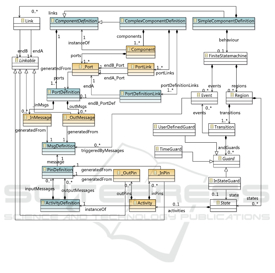
Figure 2: Excerpt of the WCOMM metamodel. Blue meta-classes model “definitions” while orange ones model “instances”.
execute the regions sequentially or concurrently, de-
pending on the platform features (e.g., CPU charac-
teristics) and the user desires. Transitions are trig-
gered by events, which can be produced by message
reception or by the results of an internal computation.
States can contain one activity instance, which is a
proxy of the concrete algorithm that will be executed
when the state becomes the region’s active state.
3.2 Executing Component-based
Applications with FraCC
In order to execute WCOMM components we devel-
oped FraCC, which comprises a deployment meta-
model (shown in Fig. 3), a C
++
framework and a model
loader that instantiates the framework according to
a WCOMM and deployment models, and a set of
model transformations that generate a default deploy-
ment model and the skeletons of the C
++
classes where
the user must add the application specific code. The
FraCC meta-model comprises three sets of classes,
ordered vertically in the figure: (i) hardware defini-
tion, since we want to extend the approach to multi-
core and distributed systems; (ii) concurrency defi-
nition, defining the number of processes and threads
where the regions that define the component behavior
will be executed; and (iii) allocation of processes and
threads to the hardware (nodes and CPU cores) that
will execute them.
From the information contained in the WCOMM
and deployment models, a model transformation gen-
erates an analysis file for the Cheddar schedulabil-
ity tool, which checks whether the final application
will meet its timing requirements or not. Appropriate
changes can be made in the applications models as
needed based on the outcomes of analysis. A detailed
description and examples of the use of the deploy-
ment model and schedulability analysis are provided
in (Ortiz, 2014). The deployment model provides
C-Forge with flexibility since it can test components
with various deployment configurations, e.g. same ar-
ICSOFT-EA 2016 - 11th International Conference on Software Engineering and Applications
106
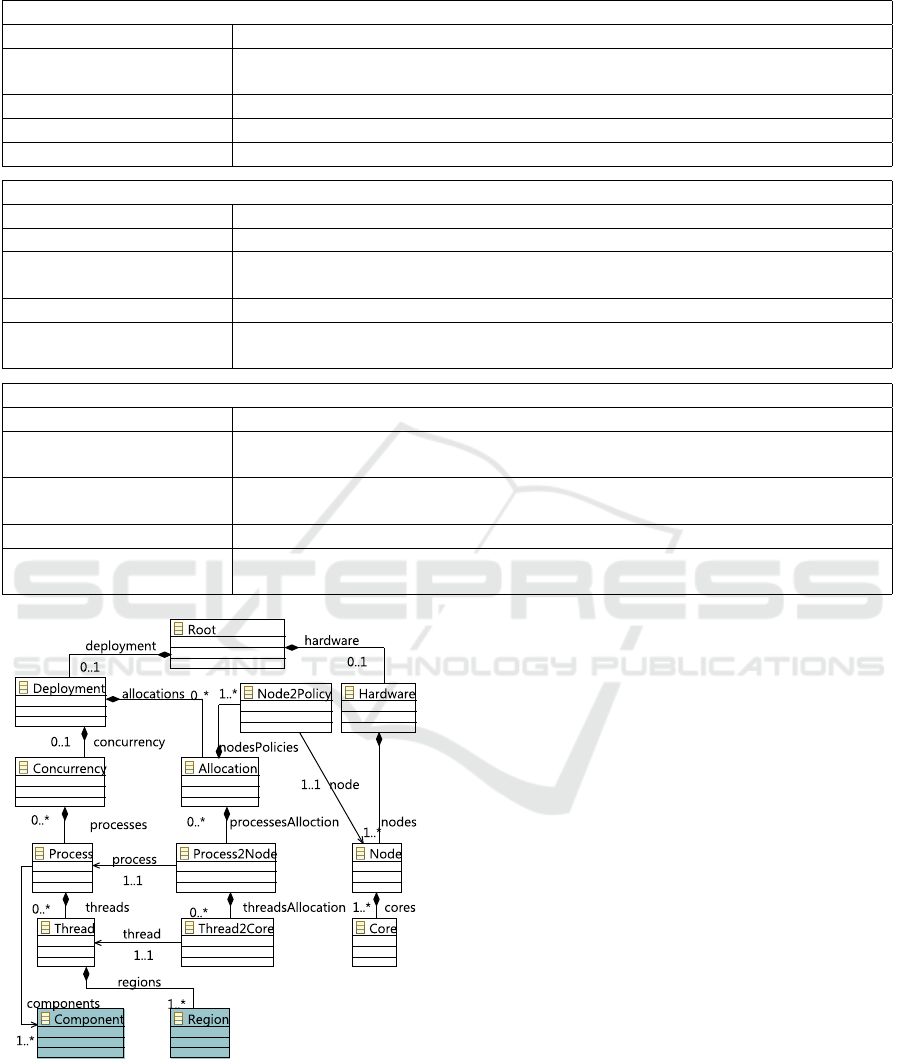
Table 1: Features of and MinFr component models according to the classification framework described in (Crnkovic, 2011).
A) LIFECYCLE DIMENSION
C-Forge: WCOMM+FraCC
Modeling ADL-like language (datatypes, component structure, component behavior) plus
deployment and concurrency view
Implementation C
++
framework based on pattern languages
Packaging EMF files (stored in XML format) and zip files including code in binary format
Deployment Set at compilation and at run-time
B) CONSTRUCTION DIMENSION: INTERFACE SPECIFICATION
C-Forge: WCOMM+FraCC
Interface Type Port based (message passing)
Provided/Required inter-
faces
No, in/out messages
Interface Language IDL-like and C
++
header files.
Interface Levels (syntac-
tic, semantic, behavior)
Syntactic only. However, behavioral (protocols) and semantic (pre, post condi-
tions and invariants) levels are implicitly defined in the FSMs
C) CONSTRUCTION DIMENSION: BINDING AND INTERACTION
C-Forge: WCOMM+FraCC
Connectors are architec-
tural elements
Not yet
Hierarchical composition
of components
Delegation (internal components are not accessible from outside the composite)
Interaction Styles Sender/receiver, message passing
Communication type Asynchronous without response. Synchronous interactions should be defined in
the FSM
Figure 3: Deployment metamodel for FraCC. Related
WCOMM classes are highlighted in orange.
chitecture; different platforms.
There are several changes the user can make
in order to obtain an schedulable application. On
the deployment model, he/she can reallocate regions
to other threads or to new ones, grouping together
regions with similar execution periods. On the
WCOMM model side, he/she can (i) develop new al-
gorithms, so that activities’ execution times are low-
ered, (ii) relax the timing requirements imposed over
the activities if possible, so that the load on the CPUs
can be lowered; or (iii) change the FSM describing a
component behavior, so that there are less regions to
be allocated to threads.
4 CONCLUSIONS
This paper has described a model-driven toolchain for
developing component-based application, entitled C-
Forge, which main characteristics are that (i) the same
models that are used to model the application are also
used to execute it, and (ii) the execution framework
provides the user with full control over its concur-
rency characteristics. Therefore, we take advantage
of all the benefits provided by model-driven technolo-
gies. C-Forge also includes a separation of concerns,
since the application architecture is separated from
the way it will be executed and from the concrete code
that will be executed by each component.
Reuse is also a key feature in C-Forge. We want
Modeling and Executing Component-based Applications in C-Forge
107

to stress that reuse should be taken into account at
all levels, and not only at the modeling one. In
WCOMM, reuse is achieved by separating “defini-
tions” from their “instances” in the meta-model, while
FraCC design’s enable the reuse of previously com-
piled (i.e., in binary format) activities.
Finally, we also want to highlight again that, from
our point of view, it is really important to consider
that model-driven should permeate all the steps and
tools involved in the development process. “Model-
driven” is not just a matter of the tool (e.g. Eclipse),
but rather a responsibility of the whole development
process and all involved tools. In our case, though the
FraCC framework has not been developed by using
Eclipse-based model-driven facilities, but rather C
++
,
it is nevertheless aware of the presence of models.
ACKNOWLEDGEMENTS
This work has been partially supported by the Spanish
CICYT Project Visel-TR (ref. TIN2012-39279)and
the Spanish Ministry of Economy and Competitive-
ness under the project cDrone (ref. TIN2013-45920-
R).
REFERENCES
I. Crnkovic, S. Sentilles, A. Vulgarakis, and M. R.
V. Chaudron. A classification framework for soft-
ware component models. IEEE Trans. Software Eng.,
37(5):593–615.2011.
D.C. Schmidt. Model-driven engineering. IEEE Computer,
39(2):25–31, February 2006.
I. Malavolta, H. Muccini, P. Pelliccione, and D. Tamburri.
Providing architectural languages and tools interop-
erability through model transformation technologies.
IEEE Transactions on Software Engineering, 36:119
– 140, 2010.
F. Ortiz, C. Insaurralde, D. Alonso, F. S
´
anchez, and Y.
Petillot. Model-driven analysis and design for soft-
ware development of autonomous underwater vehi-
cles. Robotica, pages 1–20, April 2014.
D. Alonso, F. S
´
anchez, J. Pastor, and B.
´
Alvarez. Embedded
and Real Time System Development: A Software En-
gineering Perspective, chapter A flexible framework
for Component based Application with Real-Time Re-
quirements and its Supporting Execution Framework,
pages 3–22. Springer-Verlag, 2014.
A. Vulgarakis, J. Suryadevara, J. Carlson, C. Seceleanu,
and P. Pettersson. Formal semantics of the procom
real-time component model. In Proc. of the 35th Eu-
romicro Conference on Software Engineering and Ad-
vanced Applications, pages 478–485.IEEE, 2009.
A. Cicchetti, F. Ciccozzi, S. Mazzini, S. Puri, M. Panunzio,
A. Zovi, and T. Vardanega.CHESS: a model-driven
engineering tool environment for aiding the develop-
ment of complex industrial systems. In Proc. of the
27th IEEE/ACM International Conference on Auto-
mated Software Engineering, pages 362–365. ACM
Press, 2012.
Patricia L
´
opez-Mart
´
ınez, Laura Barros, and Jos
´
e Drake. De-
sign of component-based real-time applications. Jour-
nal of Systems and Software, 86(2):449–467, 2013.
ICSOFT-EA 2016 - 11th International Conference on Software Engineering and Applications
108
