
Flexible Component Composition through Communication Abstraction
Fabian Gilson and Vincent Englebert
PReCISE Research Center, Faculty of Computer Science, University of Namur, Namur, Belgium
Keywords:
Software Architecture, Component Composition, Communication Abstraction, User-defined Properties.
Abstract:
Software architectures are often abstracted as a combination of reusable components connected to each other
by various means. Specifications of components’ semantics have been widely studied and many modeling
languages have been proposed from coarse-grained loosely-defined elements to operational objects with be-
havioral semantics that may be generated and executed in a dedicated framework. All these modeling facilities
have proven their advantages in many domains through either case studies or real-world applications. However,
most of those approaches either consider a subset of composition facilities, i.e. the available types of bindings
between components, or do not even consider communication properties at all, staying at behavioral-related
compatibility between components. Verifications of communication-related properties are then postponed to
the hand of software developers and finally considered at deployment-time only. Part of a general architecture
framework, we propose an abstraction formalism to specify communication paths between components. This
modeling facility relies on a taxonomy of types of links and the specifications of communication protocols.
This protocol serves as a reification element between abstract component compositions, architecture instances
and deployment infrastructure, making explicit communication-related constraints and properties.
1 INTRODUCTION
Component-based modeling languages are meant to
represent complex system architectures in order to,
among other, give a coarse-grained view of systems
and ease their understanding by the many stakehold-
ers of such systems. Many definitions of what a com-
ponent is may be found in the literature. Still, many
stick at Szyperski’s definition, stating that ” A soft-
ware component is a unit of composition with con-
tractually specified interfaces and explicit context de-
pendencies only. A software component can be de-
ployed independently and is subject to composition
by third parties. ” (Szyperski, 2002). Composition
is clearly highlighted as the central concept of a sys-
tem, components being unit of compositions. In their
seminal paper, Beugnard et al. introduced the notion
of contract-aware components where they distinguish
between syntactical, behavioral, synchronization and
quality of service aspects as key features for compo-
nent compositions (Beugnard et al., 1999).
Many formalisms have arisen to offer abstractions
to these unit of compositions, but surprisingly, qual-
ity of services (QoS) properties have been scarcely
studied or require to stick to a predefined environ-
ment. As examples, the component diagrams of
the OMG Unified Modeling Language points to be-
havioral diagrams in order to specify the underly-
ing communication facility without being able to
characterize the communication medium in an ab-
stract way (Object Management Group, 2011). Other
approaches are even more formal, requiring mod-
elers to rely on algebraic constructions (de Jonge,
2003; G
¨
ossler and Sifakis, 2005), data-only transmis-
sions (Oquendo, 2004; Society of Automotive Engi-
neers, 2012) or even restraining to one particular tech-
nological framework (Grinkrug, 2014).
We propose a facility to specify such quality of
service properties, on top of a syntactical and a
lightweight behavioral specification formalism. Our
goal is to provide system designers with easy-to-use
and extensible modeling elements to specify com-
ponent behaviors and properties of communication
paths. We rely on an architecture description lan-
guage (ADL) enhanced by composition constraints.
On the one hand, our ADL has been designed to face
many shortcomings of current component-based lan-
guages and embeds a taxonomy for component bind-
ings. On the other hand, the composition verifica-
tion mechanism ensures that abstract descriptions of
system architectures may be deployed on a target in-
frastructure, also specified with dedicated constructs.
442
Gilson, F. and Englebert, V.
Flexible Component Composition through Communication Abstraction.
In Proceedings of the 4th International Conference on Model-Driven Engineering and Software Development (MODELSWARD 2016), pages 442-449
ISBN: 978-989-758-168-7
Copyright
c
2016 by SCITEPRESS – Science and Technology Publications, Lda. All rights reserved

We also provide a substitution mechanism for compo-
nents, inspired from the duck-typing in object oriented
programming
1
.
We start our paper by reviewing some work close
to our approach in Section 2. We then give in Sec-
tion 3, a brief overview of our layered formalism to
specify software architectures. We introduce in Sec-
tion 4 a taxonomy for components’ connections. Af-
terwards, in Section 5, we describe how designers
may extend the semantics of model elements with
custom properties. In Section 6, we present the rules
applied at all levels of an architecture model to guar-
antee that a model is valid regarding its specifications.
We illustrate in Section 7 our proposal with a ficti-
tious online library system, where we also discuss its
advantages. We finally conclude in Section 8 by sum-
ming up the present work and the validation approach
we set up previously. We also consider the drawbacks
and future research tracks.
2 RELATED WORK
Probably the most widely known of component-based
modeling is the UML component diagram (Object
Management Group, 2011). As many of other lan-
guages, it relies on the definition of components con-
nected to each other via connectors through inter-
faces. Even if components and interfaces’ seman-
tics may be specified in a detailed manner, connectors
may only be refined by behavioral diagrams to further
elaborate their definitions, and QoS properties are not
addressed directly. Some profiles, like SysML (Ob-
ject Management Group, 2012), offer such features,
but they are mainly domain-specific, which limits
their usage to particular fields.
Other approaches like π-ADL (Oquendo, 2004),
or AADL (Society of Automotive Engineers, 2012)
provide formal constructions to specify, analyze, vali-
date and sometimes deploy component-based specifi-
cations. Despite all these advantages, formal methods
usually lack of understandability and scalability when
models become quite large. Furthermore, QoS prop-
erties are not always expressible in an algebraic way.
Alternative languages, like ACME (Garlan et al.,
1997), xADL (Dashofy et al., 2005) and Archi-
mate (Open Group, 2013) face the problem the other
1
Duck-typing is a technique in object oriented program-
ming where the semantics of a method relies on its signa-
ture, instead of being specified by the inheritance of a par-
ticular interface or class. It has been named in reference to
the poet James Whitcomb Riley for his well-known quote
”When I see a bird that walks like a duck and swims like a
duck and quacks like a duck, I call that bird a duck.”
way around, providing extensible constructs where
any kind of properties may be specified for modeling
elements. However, either their semantics is so vague
that most of it must be specified via user-defined prop-
erties, or communication facilities may not be refined
by properties.
In our approach, we furnish a set of reusable
communication links, with minimal semantics, as
well as the possibility to annotate them with user-
defined properties. Furthermore, we provide valida-
tion rules regarding the communication facilities be-
tween platform-independent model, platform-specific
models and target deployment infrastructures.
3 LAYERED REPRESENTATION
The present work is part of a larger architecture
framework, named pIck One, Document And tranS-
form Strategy (IODASS )
2
. We briefly sum up the
main architectural constructs used to support the over-
all modeling of software systems.
3.1 IODASS Model
The IODASS framework relies on a layered rep-
resentation of software architectures. Those
three IODASS layers are named Definition, As-
semblage and Deployment. The Definition layer
is used to give abstract specifications of an ar-
chitecture. Roughly, ComponentTypes are con-
nected to each others through Facets typed by
Interfaces via LinkTypes. Interfaces gather
semantically correlated Services and statically
typed Parameters. These connections are called
LinkageTypes. LinkTypes support one or more
Protocols. This separation between the type of
binding for components (point-to-point, for exam-
ple) and the communication protocol itself (HTTP,
for example) will be further discussed in this paper.
Within a Definition layer, infrastructure-related con-
structs may also be specified in order to describe
the target deployment environment. Those are the
NodeTypes, i.e. any type of computing node, Gates
being the physical interaction ports on these nodes,
typed by GateTypes and, last, MediumTypes that are
concrete links binding nodes (e.g. network facilities).
A Definition may be seen as a structural architectural
style, completed by the representation of a deploy-
ment infrastructure.
The Assemblage layer is a particular instantia-
tion of a Definition, with some additional constraints.
2
More details may be found in (Gilson, 2015)
Flexible Component Composition through Communication Abstraction
443
SetOfInstances are connected via their Ports in
Linkages. At this layer, running-time constraints
may be specified, such as creation relationships. An
Assemblage is somewhat comparable to a particular
instantiation of an architectural style.
The Deployment layer specifies a mapping of the
Assemblage on a representation of the target infras-
tructure, the infrastructure elements being specified at
the Definition layer too. Here, modelers can describe
a particular infrastructure of nodes and cables (or any
other type of communication medium), and also write
a set of rules to specify what kind of instances may be
deployed on what kind of computation nodes.
As we will discuss in Section 5, any modeling ele-
ment may be refined by user-defined properties in or-
der to add, among other, QoS properties. Those prop-
erties are particularly valuable when modelers want to
compare required properties of services, for example
in terms of communication throughput, and the char-
acteristics of the target deployment infrastructure.
Note that the Protocol is a central concept in our
modeling language. At each layer, any communica-
tion facility that describes the type of binding, i.e.
topological constraints between inter-connectible ele-
ments, is always related to this concept of Protocol,
specifying, those QoS-related properties.
3.2 Model Element Extensions
Many IODASS constructs may inherit from other con-
structs of the same type. Inheritance mechanism is
required for substitution purposes in order to ease
model evolution. ComponentTypes may inherit from
multiple other ComponentTypes, and may be com-
posed by inner-configurations, being sub-architecture
models. A complex ComponentType may be seen
as a black-box with visible interfaces and a particu-
lar hidden implementation. The inheritance relation-
ship means that the sub-ComponentType gathers all
external Facets from its super-ComponentTypes and
may add other externally visible Facets. It may also
overwrite its inner-configuration completely, i.e. pro-
viding a different implementation. Validity of substi-
tutions between ComponentTypes will be formalized
in Section 6 when we discuss the validity of linkages
between components.
Apart ComponentTypes, all other elements may
inherit from only one supertype. We restricted
to single inheritance for Protocols, LinkTypes,
MediumTypes, GateTypes and NodeTypes since for
all of them, multi-inheritance was unreasonable. For
instance, it would have make no sense for a particular
NodeType where hardware properties have been spec-
ified, like the CPU clock or amount of memory, could
inherit from multiple nodes with orthogonal specifi-
cations. Analogous reasoning may be applied to all
these elements.
4 A TAXONOMY OF LINK TYPES
The flexibility of component compositions is
achieved via the separation of topological con-
straints between components, i.e., how they are
connected, and the specification of communication
properties, notably QoS constraints. To this end,
we created a taxonomy of available link types used
to bind ComponentTypes to each others, and by
extension, between SetOfInstances since their
inter-connections are constrained by the style de-
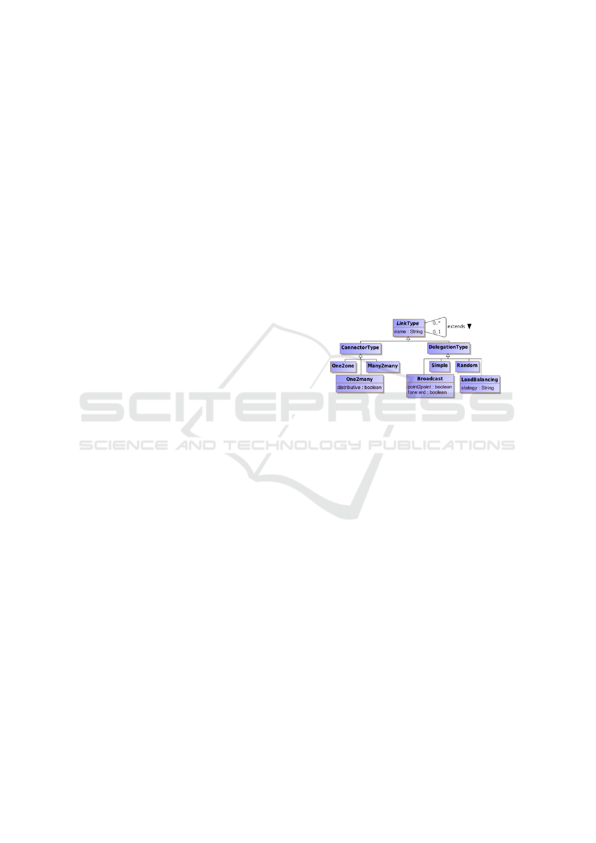
fined at the Definition layer. Figure 1 presents this
taxonomy.
Figure 1: LinkType taxonomy.
LinkTypes are either ConnectorTypes or
DelegationTypes. ConnectorTypes are used to
connect two Facets, under a provide-require contract,
analogously to the ball-and-socket in UML 2. At
the opposite, DelegationType are used to link two
Facets of the same polarity, transferring the respon-
sibility of an Interface between two components.
Both types of LinkTypes may be specialized in more
concrete constructs.
Opposite Facets may be bound to each other
in a point-to-point way (One2one), multicast way
(One2many) or in a Many2many manner. In case of
One2many, if the connection is set to be distributive,
a One2one connection is set between all instances.
In case of multiple targets (and sources), restrictions
may apply regarding the returned values of services,
since no such assumption can be taken.
Delegations between Facets may be of various
types too. A Simple delegation depicts a point-to-
point connection strictly between two instances where
the delegator will be in charge of providing the imple-
mentation for this Facet. The other types of delega-
tion describe a kind of delegation contract when mul-
tiple instances are present on the concrete implemen-
tation side. Random delegation will simply transfer
the service call to a randomly chosen implementation.
MODELSWARD 2016 - 4th International Conference on Model-Driven Engineering and Software Development
444
Broadcast means that all implementations are called
either in a point-to-point or in a multicast way. If the
connection is forward, all called implementations are
required to answer. Other LoadBlancing strategies
may also be specified. Return types for Services are
allowed for all but the Broadcast DelegationType.
These LinkTypes only concentrate on the possi-
ble topology, but does not say anything regarding the
properties of the connection itself which are under the
responsibility of the Protocol.
5 USER-DEFINED PROPERTIES
For any type of IODASS construct, particularly
Protocols, user-defined properties may be created,
as presented in Listing 1.
1 package be.iodass.sample;
2 dadproperties netwo rk {
3 enum CommunicationLayer {
4 physical , datalink , net work , transport , ses sion ,
5 presentation , application , samespace }
6 property for protocol layer {
7 type Commu nicationLayer;
8 semantics "Communication layer: seven OSI layers with an
9 extra one for processes sharing the same memory space";
}
10 property for mediumtype DataTransmiss ion {
11 type deci mal; unit "Mbits /s";
12 semantics "Maximum transmission rate in Mbits/s
13 for a network device or support"; }
14 property for mediumtype Bandwidth {
15 type int; unit "M Hz"; }
16 }
Listing 1: Sample property definitions.
A property is statically typed, targets a IO-
DASS construct and its semantics must be described.
Predefined types, such as int, or string are avail-
able, but enumerated values may also be specified
(like in the above example for CommunicationLayer).
Groups of properties may be created too, in order
to gather correlated properties in one element. This
simple mechanism allows modelers to refine the se-
mantics of many model elements as well as perform
some validation on properties where, for example, a
ComponentType requires a specific amount of disk
space or CPU power that must be provided by its de-
ployment target.
At present time, even if the verification must
be performed manually, we formalized a couple of
consistency checks regarding requirements bound to
model elements. Requirement descriptions are at-
tached to any model where the purpose and objectives
of model elements is explained
3
.
3
A complete description of the associated requirement
models may be found in (Gilson, 2015)
6 ARCHITECTURE VALIDITY
Around the separation between LinkType and
Protocol, we are now able to define validation rules
for all three layers. Those rules ensure that only valid
configurations are specified at the Definition layer,
only conforming Assemblage are created and that all
Deployment mapping rules respect the needed prop-
erties regarding connection requirements.
6.1 Validity of Component Composition
As explained in Section 3, some kind of architecture
style must be written at first. This Definition gathers
specifications of domain-specific building blocks as
well as it constraints valid configurations that may be
expressed when instantiating this abstract model.
Informally, at this stage, we must verify that all
Services of a source Facet have compatible cor-
responding Services in the target one. This loose
compatibility may be compared to a duck-typing sys-
tem, where two services are considered compatible if
at least all needed services with all needed parameters
”looks like” being covered by the provider. Matches
must be found for all required Services, but the set
of provided Services can be larger
4
. More formally,
• p denotes a Parameter, such as p = (d, g) with d the
parameter direction and g its GenericType
• e denotes an Exception
• s denotes a Service, such as
s =< p
1
, ..., p
n
>< e
1
, ..., e
m
> , an ordered list of
Parameters followed by Exceptions.
• I denotes an Interface, such as I = (s
1
, ..., s
m
) , a list of
Services
• F denotes a Facet
• |= denotes the is typed by relationship, such as F |= I
• F ∈ C denotes that the Facet F is exposed by the
ComponentType C
•
L
denotes the directed LinkageType between Facets
with a LinkType L
• a represents a LeakUsage, such that C
1
a C
2
denotes
C
1
uses C
2
For two Parameters p1 and p2, they are consid-
ered equivalent, denoted by ≈ , if formally,
p
1
= (d
1
, g
1
) ∧ p
2
= (d
2
, g
2
)
p
1
≈ p2 ⇔ d
1
= d
2
∧ g
1
= g
2
4
Note that Exceptions may be raised from Services,
and their effective handling must also be checked. The
Exceptions raised from a Service are also verified, but
the check is more stringent here. All Exceptions raised
by provided Services must be taken into account by the
required Facet
Flexible Component Composition through Communication Abstraction
445

For two Services, s
1
and s
2
, they are considered
equivalent, denoted by ≈ , if formally,
s
1
=< p
1
1
, ..., p
n
1
>< e
1
1
, ..., e
m
1
> ∧ s
2
=< p
1
2
, ..., p
n
2
>< e
1
2
, ..., e
p
2
>
s
1
≈ s
2
⇔ ∀p
k
1
∈ s
1
, ∃ p
k
2
∈ s
2
| p
k
1
≈ p
k
2
∧ ∀e
i
1
∈ s
1
, ∃e
j
2
∈ s
2
| e
i
1
= e
j
2
Then, let C
1
, C
2
two ComponentTypes and I
1
, I
2
two Interfaces. If a LinkageType has been defined
between two Facets, the following conditions must
hold:
∀ F
1
∈ C
1
, F
2
∈ C
2
| F
1
|= I
1
∧ F
2
|= I
2
F
1
L
F
2
⇒ ∀ s
i
1
∈ I
1
, ∃ s
j
2
∈ I
2
| s
i
1
≈ s
j
2
6.2 Validity of Instance Composition
At the Assemblage layer, the validation of Linkages
is analogous to the one for LinkageTypes. For a
given Port, we have to retrieve its typing Facet and
we have to ensure that the chosen Protocol for this
Port belongs to the accepted list of Protocols for
the LinkType actually used. Formally, let
• S denotes a SetOfInstance, being a set of Ports
• P denotes a Port and P ∈ S denotes that P is exposed
by S
• |= denotes the is typed by relationship, such as S |= C
• T denotes a Protocol
• L denotes a LinkType
• ` denotes the Protocol support, such that P ` T and
L ` T
If a Linkage exists between two Ports with a
LinkType L, noted by
L
, the following conditions
must hold:
∀ P
1
∈ S
1
, P
2
∈ S
2
| P
1
|= F
1
∧ P
2
|= F
2
P
1
L
P
2
⇒∃ C
1
: S
1
|= C
1
∧ ∃ C
2
: S
2
|= C
2
∧
F
1
∈ C
1
| F
1
|= I
1
∧ F
2
∈ C
2
| F
2
|= I
2
| F
1
L
F
2
∧ ∃ T | L ` T ∧P
1
` T ∧P
2
` T
6.3 Validity of Instances Deployment
Last, we must ensure that the mapping rules regarding
all connections, aka Linkages, are actually supported
by the target Deployment infrastructure. First, we
have to check that when plugging a communication
MediumType between two Gates, both Gates and the
Medium support a particular Protocol (the one that
will be used for the communication afterwards).
• N denotes a NodeType, being a set of Gates
• H denotes a Node and inherits from the Gates defined
in its typing GateType
• G denotes a GateType
• A denotes a Gate and A ∈ H denotes that A is exposed
by H
• |= denotes the is typed by relationship, such that
H |= N and A |= G
• M denotes a MediumType
• ` is overloaded such that M ` T , T supports the Pro-
tocol T
If a Plug exists between two Gates with a
MediumType M, noted by
M
, the following condi-
tions must hold:
∀ A
1
∈ H
1
∧ ∀ A
2
∈ H
2
A
1
M
A
2
⇒ ∃ T | A
1
` T ∧A
2
` T ∧M ` T
Now, when abstractly deploying instances on
nodes, Ports are bound to Gates that will effec-
tively support the connection between Nodes via
a MediumType. We have to guarantee that the
Protocol chosen to link both Ports is actually sup-
ported by the Gates and MediumType. In other words,
we must allege that when deploying a model instance,
the target infrastructure will certainly allow the com-
munication between instances. Formally,
• → denotes the Deploy rule, such that S → H
• } denotes an Opening, such that P } A , the Port P
is opened on A
Then, the following conditions, must hold:
∀ A
1
∈ H
1
∧ ∀ A
2
∈ H
2
∧ ∀ P
1
} A
1
∧ ∀ P
2
} A
2
P
1
L
P
2
∧ A
1
M
A
2
⇒ ∃ S
1
| P
1
∈ S
1
∧ ∃ S
2
| P
2
∈ S
2
∧ S
1
→ H
1
∧ S
2
→ H
2
∧ ∃ T | L ` T ∧ M ` T
∧ A
1
` T ∧ A
2
` T
7 DISCUSSION
We will now illustrate our modeling language with a
fictitious online library system. In this system, users
connect to a webpage where they can browse over
a list of books, and possibly buy some. The list of
available books is the conjunction of all catalogs sent
by partner bookstores. When a book is bought on
the library, an auction is conducted between all stores
providing the book to find the cheapest price among
them. A delivery service will then come at the win-
ning store to bring the book at the customer’s place.
MODELSWARD 2016 - 4th International Conference on Model-Driven Engineering and Software Development
446
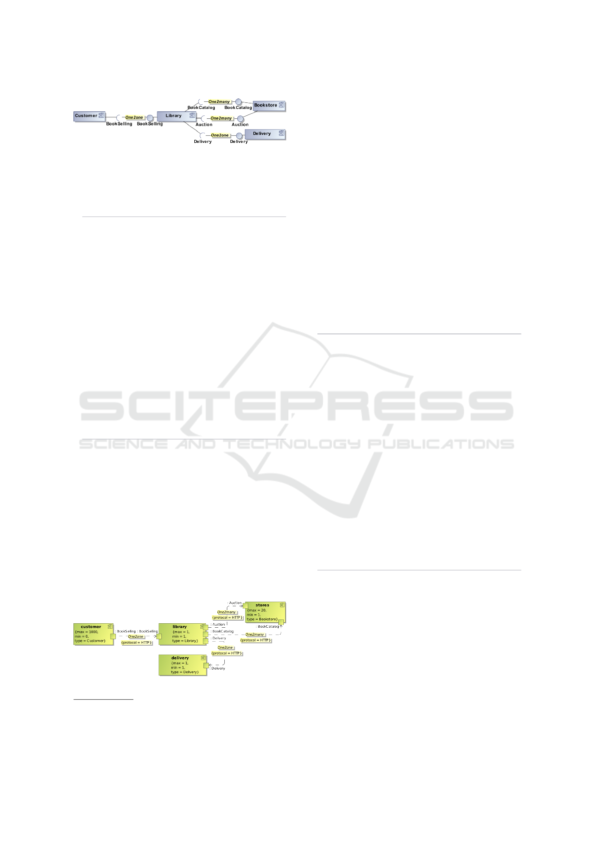
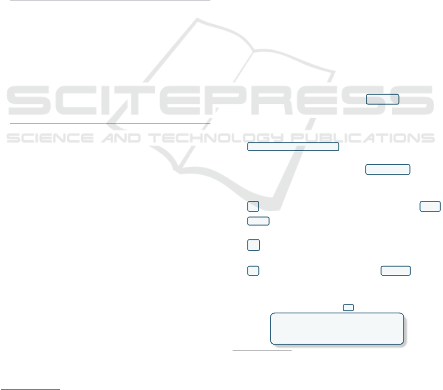
Figure 2: Component Topology (graphical representation.)
A naive graphical representation of the architecture
Definition is shown in Figure 2.
Listing 2 shows the corresponding textual model
5
.
1 package be.iodass.onlinelibrary ;
2 dadmodel onlinelibrary {
3 definition {
4 struct Book { /
*
book details
*
/ }
5 interface BookSelling {
6 sync Book[] browseCatalog();
7 sync boolean buyBook(in int isbn);
8 event confirmDelivery ( Book b); }
9 interface BookCatalog { sync Book[] getBookCatalog () ; }
10 interface Au ction {
11 sync float getPrice(in int isbn, in float p); }
12 interface Delivery {
13 sync boolean deliverBook(in Book b); }
14 componenttype Cu stomer{ uses BookSelling as bs; }
15 componenttype Libra ry {
16 implements BookSelling as bs; /
*
for customer
*
/
17 uses BookCatalog as bc; /
*
to stores
*
/
18 uses Auction as a; /
*
to stores
*
/
19 uses Delivery as d; /
*
to delivery
*
/ }
20 componenttype Bookstore {
21 implements BookCatalog as bc;
22 implements Auction as a; }
23 componenttype De livery { implements Delivery as d; }
24 connectortype On e2many { mode one2many; }
25 connectortype One2o ne { mode one2one; }
26 // connections
27 linkagetype from Customer.bs to Library.bs with One2one;
28 linkagetype from Library.bc to Bookstore.bc with On e2many;
29 linkagetype from Library.a to Bookstore .a with One2many;
30 linkagetype from Library.d to Delivery.d with One2one; }
31 }
Listing 2: Definition layer (Component Topology).
For this naive model, connections are simply
drawn between ComponentTypes, but no assump-
tions regarding Protocols have been set. Only the
way how connections should be made (point-to-point
or not) is stated.
We will now refine the definitions of both connec-
tor types illustrated in previous model to make them
accept a particular Protocol, also defined in List-
ing 3. Figure 3 first shows a simplified representation
of the Assemblage layer conforming to the (updated)
Definition layer given in previous listing.
Figure 3: Graphical Component Instantiation.
5
We created an Eclipse plugin available at https://sites.
google.com/site/memodiaresearchproject/
An Assemblage model is a kind of instantiation
of a Definition model completed with some runtime
constraints, as briefly stated in Section 3. For exam-
ple, a library instance may handle up to 1000 cus-
tomers at the same time, but none of them is required.
On the other hand, at least one stores and one de-
livery instances are needed to make the system run
correctly. Linkages are represented by directed ar-
rows, depicting which instance is initiating the call
(called instance being at the arrow’s side). Linkages
are also annotated by one particular Protocol, cho-
sen from the list of available protocols accepted by
the Facets specified at the Definition layer. List-
ing 3 shows the complete updated model with the new
Protocol, the modified ConnectorTypes as well as
the Assemblage. Note that, the IODASS modeling lan-
guage allows model imports (using the import key-
word). Existing elements from the imported model
(names are fully qualified) are simply overridden by
their new definitions in the new model, if any.
1 package be.iodass.onlinelibrary ;
2 import be.io dass .onlinelibrary.onlinelibrary;
3 dadmodel onlinelibrary_2 {
4 definition {
5 protocol HTTP {
6 layer: application; reliable: true; ordered: true; }
7 connectortype One2o ne { mode one2one; accepts HTTP; }
8 connectortype On e2many {
9 mode one2many; distributive: true; accepts HTTP; }
10 }
11 assemblage {
12 // up to 1000 simultaneous customers
13 soi customer [0 1000] : Customer {
14 Customer.bs as bs on HTTP; }
15 soi library : Library { // library is unique
16 Library.bs as bs on HTTP; Li brary.bc as bc on HT TP;
17 Library.a as a on HTTP; Library.d as d on HTTP; }
18 // up to 20 stores, but at least one
19 soi stores [1 20] : Bookstore {
20 Bookstore.bc as bc on HTTP;
21 Bookstore.a as a on HTTP; }
22 // the deliverer is unique
23 soi delivery : ParcelDelivery { D elivery.d as d on HTTP;
}
24 // up to 10 request can be handled at a time
25 linkage from customer.bs [0 10 ] to library .bs with One2one
;
26 // library can be linked to 1 to 20 stores
27 linkage from library.bc to stores.bc [1 20] with One2many;
28 // library can be linked to 1 to 20 stores
29 linkage from library.a to stores.a [1 20] with One2many;
30 linkage from library.d to delivery.d with One2one; }
31 }
Listing 3: Assemblage layer (Component instantiation).
Last, we can specify a target infrastructure that
will support this particular Assemblage. To this end,
new constructs may be defined to represent the net-
work of computation nodes and cables with their own
properties. Figure 4 gives an overview of a target De-
ployment infrastructure.
A couple of new constructs have been introduced
comparable to UML 2 nodes and communication
paths, but their semantics may be refined with more
details, and open the possibility to validate an archi-
tecture deployment regarding some properties. Also,
Flexible Component Composition through Communication Abstraction
447

Figure 4: Graphical Component Deployment.
instead of using stereotypes, we rely on semantics in-
heritance for modeling elements. The updated model
is given in Listing 4.
1 package be.iodass.onlinelibrary ;
2 import be.io dass .onlinelibrary.onlinelibrary_2;
3 dadmodel onlinelibrary_3 {
4 definition {
5 // create a gatetype that accepts HTTP requests
6 gatetype Ethernet { supports HTTP; }
7 // node types
8 nodetype Client { Ethe rnet e th0; }
9 nodetype BasicServer { Ethernet eth0; }
10 nodetype Gateway { Ethernet [3] eth;}
11 nodetype Server extends BasicServer {
12 Ethernet e th1;
13 CPU : 3.2 ; CPUCore : 4;
14 CPUArchitecture : "Intel Itanium"; }
15 // two types of media
16 mediumtype Cable {
17 supports HTTP; DataTransmiss ion : 1.5; }
18 mediumtype E100BaseT extends Cable {
19 Bandwidth : 100; DataT ransmission : 100; }
20 }
21 deployment {
22 node bser ver[21] : BasicServer;
23 node server : Server;
24 node gate way : Gateway;
25 node client[1000] : Client;
26 // deploy all set of instances
27 deploy customer[0 999] on client[0 999];
28 deploy library on server[0];
29 deploy store s on bserver[0 19];
30 deploy delivery on server [20];
31 site T heOffice { contains server, gateway ; }
32 // open ports on network gates
33 open libr ary.bs on server ::e th0; // customer
34 open libr ary.bc on server ::e th1; // book catalog
35 open stores.bc on bserver [0 19]::eth0;
36 open libr ary.a on server ::eth1; // auction
37 open stores.a on server[0 19]:: eth0;
38 open libr ary.d on server ::eth1; // delivery
39 open d elivery.d on server [20]::eth0;
40 // bind nodes to each other
41 plug Cable from cl ient [0 999]:: eth0 to gateway::gengate;
42 plug E 100BaseT from server::eth0 to gateway ::eth[0];
43 plug E 100BaseT from server::eth1 to gateway ::eth[1];
44 plug Cable from gateway ::gengate to bserver [0 21]::eth0; }
45 }
Listing 4: Component Deployment (textual representa-
tion).
In the above listing, a GateType is created in order
to type the Gates available on the NodeTypes. Those
Gates express, among others, what kind of Protocol
they accepts. For example, an Ethernet port on a
personal computer will not be able to accept WiFi
connections. The GateType is literally representing
this constraint, any type of physical port on a com-
puter (or any other likewise device) are not able to re-
ceive any type of communication. Moreover, even if
this port supports a particular protocol, more stringent
constraints may exist at the Definition or Assemblage
layers regarding needed data transmission rate, for in-
stance. Here again, user-defined properties serve the
role of validation helpers for these kind of constraints.
For illustration purposes, we also added such proper-
ties to the Server to refine its semantics in terms of
computation architecture. It also inherits from the Ba-
sicServer, meaning that it owns two Ethernet Gates.
Exactly as model elements may be completely over-
ridden (when importing a model), specific properties
may be overridden too, like the DataTransmission in
the E100BaseT MediumType.
The Deployment clause in the above model de-
scribes then one concrete deployment of the Assem-
blage onto a target infrastructure. In short, instances
must be deployed on Nodes, their Ports must be
opened on Gates and MediumTypes must be plugged
into those Gates. Shorthand rules may contain in-
dexes interval in order to limit the number of lines of
code to write (as in lines 53, 57 and 63).
Hence, the overall communication paths, from the
Definition layer to the Deployment layer is reified
around the concept of Protocol, making possible to
specify a very wide range of communication facilities
and, in some ways, validate the conformance between
an abstract architecture model, a particular instanti-
ation and its target deployment infrastructure. The
Protocol acts as a central point used in both the As-
semblage and Deployment layers around which con-
nection facilities are bound, such that any constraint
expressed in connection paths and their connected
elements (ComponentTypes, SetOfInstances or
Nodes) can be verified. Since properties are stati-
cally typed (sometimes with an ordering rule), verifi-
cations may be performed between needed properties
(expressed in the aforementioned requirement models
in Section 5) and actual properties offered by a model.
8 CONCLUSIONS, LIMITATIONS
AND FUTURE WORK
A recent survey regarding the need of modeling sup-
port for software architecture conducted in the indus-
try showed that, even if many theoretically powerful
frameworks have been proposed for the last twenty
years, the most popular language was still UML2
component diagrams (Malavolta et al., 2013). This
survey also highlighted that, (non-) practitioners are
also interested in iterative design support, model ver-
sioning and analysis, and also in the ability to repre-
sent a wide range of architecture and communication
facilities using the same tweakable formalism.
MODELSWARD 2016 - 4th International Conference on Model-Driven Engineering and Software Development
448

In previous work, we detailed our contribution re-
garding the design support and model versioning, but
we did not demonstrate how our architecture frame-
work may help architects for analysis and flexible
component compositions. In the present work, we ex-
plained how components may be substituted by other
ones having compatible external definitions using a
special kind of inheritance mechanism inspired from
the object-oriented duck-typing concept. We also pro-
vided a taxonomy of link types between components
for both provide-require contracts as well as for del-
egation ones. We introduced a clear separation be-
tween topological configurations of components, sup-
ported by the aforementioned taxonomy, and the be-
havioral or Quality of Service properties whose re-
sponsibility is transfered in a dedicated protocol mod-
eling construct.
The overall framework has been subject to an em-
pirical validation, even if its size was rather small and
the participants were master students (Gilson, 2015).
However, despite its limitations, the case study high-
lighted some advantages in terms of model complete-
ness and in terms of expressiveness regarding model-
ing communication facilities.
Tool support is provided for the overall frame-
work, as an Eclipse plugin, enabling designers to
write and transform models in order to refine, up-
date or modify them in a structured and fully traceable
way. The validation of composition and substitutions
presented in this paper are fully part of that tool.
Still, the mechanism provided to write user-
defined properties has been thought in an automat-
able way, validation of properties is, at present time,
a manual task. When the size of model increases,
such an automated validation is particularly needed,
especially when model elements may be substituted
easily (by model transformations in our case). How-
ever, this validation feature can be added in the tool
support with reasonable effort, especially because we
already provided a theoretical ground regarding con-
sistency verifications between properties. Combined
to the user-defined properties, other behavioral speci-
fications could be envisioned.
At present time, only static relations between
properties are defined, but the property mechanism
could be extended to specify relations between prop-
erties of different constructs. For example, some kind
of relation could be expressed between the response
time of a server, the data transmission rate of its con-
nected communication medium and its CPU capac-
ity. Such complex relations would help the aforemen-
tioned validation feature to higpossible problems in
architecture models for correlated properties, without
requiring to specify each time the mapping between
those properties.
Last, no inheritance exists for data types (e.g. in-
terfaces, parameter types or data structures). Such
inheritance would raise the flexibility for component
composition and substitution, but would require to
enhance our compatibility verifications to handle co-
and contravariance of data types.
REFERENCES
Beugnard, A., J
´
ez
´
equel, J.-M., Plouzeau, N., and Watkins,
D. (1999). Making components contract aware. Com-
puter, 32(7):38–45.
Dashofy, E. M., Hoek, A. v. d., and Taylor, R. N. (2005). A
comprehensive approach for the development of mod-
ular software architecture description languages. ACM
Trans. Softw. Eng. Methodol., 14(2):199–245.
de Jonge, M. (2003). To Reuse or to be Reused - Techniques
for Component Composition and Construction. PhD
thesis, Universiteit van Amsterdam.
Garlan, D., Monroe, R. T., and Wile, D. (1997). Acme:
An architecture description interchange language. In
Conference of the Centre for Advanced Studies on
Collaborative research (CASCON 97), pages 169–
183, Toronto, Ontario.
Gilson, F. (2015). Transformation-Wise Software Architec-
ture Framework. Presse Universitaire de Namur, Na-
mur (Belgium). Ph.D. Thesis.
G
¨
ossler, G. and Sifakis, J. (2005). Composition for
component-based modeling. Science of Computer
Programming, 55(1–3):161 – 183. Formal Methods
for Components and Objects: Pragmatic aspects and
applications.
Grinkrug, E. (2014). Dynamic component composition. In-
ternational Journal of Software Engineering & Appli-
cations, 5(4).
Malavolta, I., Lago, P., Muccini, H., Pelliccione, P., and
Tang, A. (2013). What industry needs from architec-
tural languages: A survey. IEEE Trans. Softw. Eng.,
39(6):869–891.
Object Management Group (2011). OMG Unified Model-
ing Language (OMG UML), Superstructure, version
2.4.1, chapter 8, pages 161–182. Object Management
Group. OMG document formal/2011-08-06.
Object Management Group (2012). OMG Systems Model-
ing Language (OMG SysML™), version 1.3. OMG
document formal/2012-06-01.
Open Group (2013). Open Group Standard ArchiMate®2.1
Specification. Document Number: C13L.
Oquendo, F. (2004). π-adl: an architecture description
language based on the higher-order typed π-calculus
for specifying dynamic and mobile software archi-
tectures. SIGSOFT Software Engineering Notes,
29(3):1–14.
Society of Automotive Engineers (2012). Architecture
Analysis & Design Language (AADL). Standard
number AS5506 Revision: B.
Szyperski, C. (2002). Component Software: Beyond
Object-Oriented Programming. Addison-Wesley
Longman Publishing Co., Inc., Boston, MA, USA,
2nd edition.
Flexible Component Composition through Communication Abstraction
449
