
Toward a Computational Model of Actin Filament Networks
Andrew Schumann
University of Information Technology and Management in Rzeszow, Sucharskiego 2, Rzeszow, Poland
Keywords:
Actin, Swarm Computing, Slime Mould Computing, Networks.
Abstract:
Actin is one of the most important proteins responsible for a reaction of cells to external stimuli (stresses).
There are monomeric actin or G-actin and polimeric actin or F-actin. Monomers of G-actin are connected
into double helical filaments of F-actin by the processes of nucleation, polymerization, and depolymerization.
Filaments are of 7-8 nm in diameter. They are of several microns in length. Furthermore, filaments can be
organized as complex networks of different forms: unstable bunches (parallel unbranched filaments), trees
(branched filaments), stable bunches (cross-linked filaments). Actin filament networks can be considered a
natural computational model of cells to perform different responses to different external stimuli. So, in this
model we have inputs as different stresses and outputs as formations and destructions of filaments, on the
one hand, and as assemblies and disassemblies of actin filament networks, on the other hand. Hence, under
different external conditions we observe dynamic changes in the length of actin filaments and in the outlook
of filament networks. As we see, the main difference of actin filament networks from others including neural
networks is that the topology of actin filament networks changes in responses to dynamics of external stimuli.
For instance, a neural network is a sorted triple (N,V, w), where N is the set of neurons/processors, V is a set
of connections among neurons/processors, and w is a weight for each connection. In the case of actin filament
networks we deal with a variability of filaments/processors. Some new filaments/processors can appear in one
conditions and they can disappear in other conditions. The same situation when the computational substratum
changes during the time of computations is faced in the so-called swarm computing, e.g. in slime mould
computing. In this paper we propose a swarm computing on the medium of actin filament networks.
1 INTRODUCTION
In machine learning there have been used some bio-
logically inspired networks such as artificial neural
networks, where we have a fixed number of proces-
sors involved into computations. However, elemen-
tary computational units understood as processors in
real biological networks are never fixed. They are be-
ing built and rebuilt permanently in responses to dif-
ferent stresses as external conditions. One of the best
examples of these units in biological networks is pre-
sented by actin filaments. Their networks are most
important in remodelling cell configurations and in
the cell motility. The point is that actin filament net-
works are engaged in changing the cell shape, for ex-
ample in the division of one cell into two daughter
cells and in the protrusion of parts of the cells, e.g. in
the cell deformation by means of growing pseudopo-
dia during phagocytosis. Meanwhile, the actin fila-
ments are being assembled and disassembled during
the time. As a consequence, we face a permanent as-
sembly and disassembly of actin filament networks.
These changes in networking are cell responses to
different stimuli. For instance, actin filament net-
works by the own reconstruction can transmit inter-
nal stresses and govern the spatial organization of the
cytoskeleton. So, these networks can provide signal
transduction pathways and make a mechanical equi-
librium of the cell and its environment.
The actin filament networks react to external
stresses. These stresses are inputs for the networks.
There are three main types of the actin filament net-
works: unstable bunches (parallel unbranched fila-
ments), trees (branched filaments), stable bunches
(cross-linked filaments), see: (Furukawa et al., 1993;
Steinmetz et al., 1997). Outputs are different for
different network types. For unstable bunches and
trees, the outputs are represented by chemotaxis, cell
spreading, nerve growth-cone movement, etc. For sta-
ble bunches, the outputs have the form of mechanic
stress transduction such as (i) a tensional stress in
the distortion to the network; (ii) a curvature stress in
the deformation of the network; (iii) an orientational
stress in the deformation of the network.
290
Schumann, A.
Toward a Computational Model of Actin Filament Networks.
DOI: 10.5220/0005828902900297
In Proceedings of the 9th International Joint Conference on Biomedical Engineering Systems and Technologies (BIOSTEC 2016) - Volume 4: BIOSIGNALS, pages 290-297
ISBN: 978-989-758-170-0
Copyright
c
2016 by SCITEPRESS – Science and Technology Publications, Lda. All rights reserved

Due to actin filaments, the amoeboid cell motil-
ity is possible. In robototechnics, one species of the
Mycetozoan group of the Amoebozoa, which is char-
acterized by this kind of motility, is best studied. It
is Physarum polycephalum. In the project Physarum
Chip Project: Growing Computers From Slime Mould
(Adamatzky et al., 2012) supported by FP7 we have
designed an unconventional computer on plasmodia
of Physarum polycephalum. Each plasmodium has
both an external stationary ectoplasm and an inter-
nal liquid endoplasm that moves to pseudopodia. The
amoeboid motility is classified by the following three
stages: (i) the stage of growing pseudopodia; (ii) the
stage of attaching the pseudopodium to a substrate;
(iii) the stage of dragging up the rest of the cell (Fack-
ler and Grosse, 2008; Pollard and Borisy, 2003). Such
a movement requires an oscillatory mode of contrac-
tility system where an actin filament network is be-
ing assembled and disassembled for an equilibrium
between ectoplasm and endoplasm (Furuhashi et al.,
1998). Hence, the Physarum polycephalum plasmod-
ium motility that is so intelligent and can be pro-
grammed by using chemotaxis so that we can design
computers on their media is based on some actin fila-
ment network properties.
Actin filament networks are a universal mecha-
nism in the reception and further transmission of ex-
ternal stimuli/stresses in any biological organism. By
chemicals it is possible to govern an actin polymerisa-
tion and depolymerisation, i.e. the filament assembly
and disassembly. For instance, on the one hand, cy-
tochalasin B, the cell-permeable mycotoxin, strongly
inhibits the formation of actin filament networks. On
the other hand, the mycotoxin of Amanita phalloides
strongly activates the aggregation of all cell G-actin
into filaments which become Ph-actin and cannot be
depolymerised and thus this taxin avoids any dynam-
ics of cytoskeleton.
Hence, theoretically we can assume that it is pos-
sible to synthesize and then govern/program an ar-
tificial actin filament network. This network is fun-
damental in any cell reaction to stimuli. As a result,
this artificial network could be considered a biological
computer/chip as such. Its computational processes
would be primary for organic intelligence in princi-
ple. Some computational features of actin filament
network are as follows:
• We deal with a system (N
0
,V
0
, w
0
), where (i) N
0
is
a non-well-founded set of processors called “fil-
aments”; this set is non-well-founded, because it
is impossible to divide N
0
into atoms or even just
into excluded subsets n
j
which form a partition
of N
0
=
F
j
n
j
; in other words, processors are be-
ing redesigned permanently and they can appear
and disappear and ever change own features; (ii)
V
0
is a set of tuples {(i
t
, j
t
): i
t
, j
t
∈ N
0
} whose
elements are connections between filament i
t
and
filament j
t
at time step t; hence, the set V
0
is non-
well-founded, too, as its cardinality can change
during the time t; (iii) w
0
is a function from V
0
to
∗
R, where
∗
R is a set of hyperreal numbers
such that w
0
((
∗
i,
∗
j)), where
∗
i = i
0
i
1
i
2
i
3
, . . . and
∗
j = j
0
j
1
j
2
j
3
. . . , for short w
∗
i,
∗
j
, is called the
weight of the connection between filament
∗
i and
filament
∗
j at each time step t = 0, 1, 2, 3, . . . ; no-
tice that a filament
∗
i can be hidden (not present)
at actual time.
• Each filament behaves as an artificial organism
(e.g. as an artificial cell): (i) it can grow up; (ii)
its behaviour can be attracted/directed by chemo-
taxis. In cells there are ever filaments, some of
them ‘die’ and some others ‘born’.
• Each unstable actin filament network behaves as
an artificial swarm: (i) it can grow up; (ii) its be-
haviour can be attracted/directed by chemotaxis
(Van Haastert and Devreotes, 2004); (iii) there can
be a fusion of two swarms (two actin filament net-
works) into one swarm (one network); (iv) there
can be a splitting of one swarm (one network) into
two swarms (two networks). In cells there are ever
some actin filament networks.
• Each cross-linked actin filament network behaves
as a metaswarm: it reacts to mechanical external
stimuli and it can be partly reorganized.
Thus, in constructing the actin filament network
(N
0
,V
0
, w
0
) we have the following three levels of com-
putations: (i) an artificial organism (filament); (ii)
an artificial swarm (unstable bunch or tree); (iii) a
metaswarm (stable bunch). On all three levels we
face an instability of computation substratum. So, we
assume that an actin filament chip changes its con-
figurations during the computation processes. In de-
signing this chip we can appeal to swarm computing,
e.g. to slime mould computing. In the same measure
as the neural networks, the actin filament networks
can be used in pattern recognitions. So, due to the
actin filament networks any slime mould can recog-
nize its dynamic environment and occupy the pieces
of food/attractants.
In this paper we consider some basic features of
artificial actin filament networks. In Section 2 we
concentrate on computational properties of unstable
actin filament networks. In Section 3 on properties of
stable actin filament networks. All constructions of
this paper are pioneering.
Toward a Computational Model of Actin Filament Networks
291

2 ACTIN FILAMENTS AS
SWARMS
In any cell there is a huge number of actin monomers
or globular actin (the so-called G-actin) denoted by
A
i
. Monomers are involved into computations only
within actin filaments, minimally consisting of three
actin monomers. G-actin A
i
can assemble into double
helical filaments of 7-8 nm in diameter and of several
microns in length.
Filaments are (re)designed by the processes of nu-
cleation, polymerization, and depolymerization:
• Nucleation. For nucleation that allows monomers
to be assembled into filaments it is enough to
bound three G-actin monomers at first. Then for
enlargement an actin filament must be polarised
with a barbed end that is plus at which monomer
addition is faster than at the pointed end that is
minus. So, actin filaments are morphologically
asymmetric with different kinetic characteristics
at two ends, and this fact helps to polymerize fil-
amentous actin (the so-called F-actin) from the
head (plus end) to the tail (minus end), see please
(Holmes et al., 1990; J. Hu et al., 2007).
• Polymerization. It is an association of new fil-
aments mediated by actin cross-linking proteins:
α-actinin, fascin, fimbrin, and filamin. This as-
sembly is carried out on the basis of adding new
monomers at the barbed end. Meanwhile, at the
steady state, when a filament finishes to grow, the
net rate of disassembly matches the rate of assem-
bly at the plus end (Goldmann et al., 1998).
• Depolymerization. It is a dissociation of filaments
which takes place when the critical concentration
for actin polymerization is less than the dissocia-
tion constants at the two filament ends (Coluccio
and Tilney, 1983).
Thus, an actin filament consists of two filament
strands in the helical form. For each actin monomer
A
i
in both strands there are three possible states:
bound on the left, lA
i
; bound on the right, rA
i
; and
bound on both sides, bA
i
. Out of any filament, the
monomer A
i
is considered free, f A
i
, or turned off.
Monomers in the first strand are distinguished by sA
•
i
,
where s ∈ {l, r, b}. Monomers in the second strand are
distinguished by sA
◦
j
, where s ∈ {l, r, b}.
Definitions 1. Polymerization is a process calculus
defined as follows:
names ::= f A
i
|, lA
•
i
|rA
•
i
|bA
•
i
|lA
◦
j
|rA
◦
j
|bA
◦
j
;
&, bounding ::= if f A
j
&rA
i
, then
f A
j
→
&
rA
i+1
and rA
i
→
&
bA
i
|
if f A
j
&lA
i
, then
f A
j
→
&
lA
i−1
and lA
i
→
&
bA
i
|
if lA
j
&rA
i
, then
lA
j
→
&
bA
i+1
and rA
i
→
&
bA
i
|
if bA
i+i
&lA
i
, then
if lA
i
→
&
bA
j+1
, then bA
i+1
→
&
bA
j+2
|
if rA
i+i
&lA
i
, then
if lA
i
→
&
bA
j+1
, then rA
i+1
→
&
rA
j+2
|
if rA
i+i
&bA
i
, then
if bA
i
→
&
bA
j+1
, then rA
i+1
→
&
rA
j+2
|
if f A
i
& f A
j
, then
f A
i
→
&
rA
j+1
and f A
j
→
&
lA
j
or
f A
i
→
&
lA
i
and f A
j
→
&
rA
i+1
,
where ∈ {◦, •} and A →
&
B is a renaming of
monomer A by a new name B after the bounding;
P, processes ::= & | P
1
|P
2
.
In this definition we have defined filaments as
growing from the right side. So, a free monomer f A
i
can interact with another free monomer f A
j
and, as
a result, we can have a strand rA
j+1
lA
j
or a strand
rA
i+1
lA
i
. A free monomer f A
i
can also interact with
a monomer lA
j
, and, as a result, we obtain a strand
. . . bA
j
lA
j−1
. A free monomer f A
i
can also interact
with a monomer rA
j
, and, as a result, we obtain a
strand rA
j+1
bA
j
. . . . A monomer rA
i
can associate
with a monomer lA
j
to give a strand . . . bA
i+1
bA
i
. . .
Definitions 2. Depolymerization is a process calcu-
lus defined as follows:
names ::= f A
i
|, lA
•
i
|rA
•
i
|bA
•
i
|lA
◦
j
|rA
◦
j
|bA
◦
j
;
&, unbounding ::= if bA
i+1
&bA
i
, then
bA
i+1
→
&
lA
j
and bA
i
→
&
rA
i
|
if bA
i+1
&lA
i
, then
bA
i+1
→
&
lA
i+1
and lA
i
→
&
f A
i
|
if bA
j
&rA
j+1
, then
bA
j
→
&
rA
j
and rA
j+1
→
&
f A
j+1
|
if rA
i+i
&lA
i
, then
rA
i+1
→
&
f A
i+1
and lA
i
→
&
f A
i
,
where ∈ {◦, •} and A →
&
B is a renaming of
monomer A by a new name B after the unbounding;
P, processes ::= & | P
1
|P
2
.
BIOSIGNALS 2016 - 9th International Conference on Bio-inspired Systems and Signal Processing
292

Hence, a monomer lA
i
can dissociate from a
strand . . . bA
i+1
lA
i
or a strand rA
i+1
lA
i
and to be-
come a free monomer f A
i
. A monomer rA
i+1
can dissociate from a strand rA
i+1
lA
i
or a strand
rA
i+1
bA
i
. . . and to become a free monomer f A
i+1
. A
strand . . . bA
i+1
bA
i
. . . can be divided into two strands
. . . lA
i+1
and rA
i
. . . .
Let [sA
i
], where s ∈ {l, r, b}, mean a value of sA
i
:
(i) [sA
i
] = 1 iff sA
i
is excited; and (ii) [sA
i
] = 0 iff
sA
i
is not excited. A signal is transmitted in filaments
. . . bA
i+1
lA
i
form the left to the right hand and the
signal transmission defined as follows:
[bA
◦
i
] =
1, if either [bA
◦
i+1
] ∧ [bA
•
i+1
] = 1 or
[bA
◦
i
] ∧ [bA
•
i
] = 1;
0, otherwise.
[bA
•
i
] =
1, if either [bA
•
i+1
] ∧ [bA
◦
i+1
] = 1 or
[bA
•
i
] ∧ [bA
◦
i
] = 1;
0, otherwise.
[lA
◦
i
] =
1, if [bA
◦
i+1
] ∧ [bA
•
i+1
] = 1;
0, otherwise.
[lA
•
i
] =
1, if [bA
•
i+1
] ∧ [bA
◦
i+1
] = 1;
0, otherwise.
Each filament is instable because of the faster net
loss of G-actin at the pointed end than at the barbed
end and the faster net addition at the barbed end than
at the pointed end. If there is an equilibrium of two
rates of association and dissociation, it gives rise to a
treadmilling when there is a net flow of actin subunits
through the filament (Svitkina and Borisy, 1999). The
rate of treadmilling may be altered by the inhibition
of disassembly at the pointed end, e.g., by mM phos-
phate (Coluccio and Tilney, 1983). Increasing the rate
of monomer dissociation at the pointed end, e.g., by
cofilin can accelerate treadmilling, also. Proteins that
control treadmilling of actin filaments and their adhe-
sions are classified as follows:
C, control ::= SeqP | CrossP | SevP | NucP,
where
• SeqP are sequestering proteins: (i) β-thymosins
which sequester G-actin to prevent spontaneous
nucleation; (ii) profilin which interacts with actin
monomers to enhance nucleotide exchange (Car-
lier et al., 1994);
• CrossP are cross-linking proteins: (i) α-actinin
which cross-links the actin filaments; (ii) vin-
culin, talin, and zyxin which link the cortex to
the plasma membrane (Chhabra and Higgs, 2007;
Choi et al., 2008);
• SevP are severing proteins: (i) cofilin (actin de-
polymerization factor) which sever F-actin to gen-
erate more filament ends for assembly or dis-
assembly and enhances subunit dissociation; (ii)
gelsolin and the Arp2/3 complex (containing the
actin-related proteins, Arp2 and Arp3) which cap
filament ends to regulate addition or loss of actin
subunits, see: (Iwasa and Mullins, 2007);
• NucP are nucleating proteins: (i) formin, the
Arp2/3 complex which nucleate filament growth;
(ii) integrins which nucleate the formation of as-
semblies of structural and signaling proteins for
filament adhesions (Balaban et al., 2001).
Actin filaments can be organized as bunches in re-
sponse to the activation of signalling pathways by ex-
ternal stimuli. The basic processes in filament bunch-
ing are as follows:
• Anchoring. As response to external stimuli the
actin filaments anchor to membranes. Meanwhile,
filaments are attached at their plus ends so that
the filament elongation occurs at anchored ends
which can cause a membrane deformation in the
form of growing pseudopodia.
• Parallel orientation. Usually, actin filaments are
short, randomly oriented, and not bundled. Exter-
nal stimuli organize actin filaments in linear pat-
terns with orientation of filament heads towards
stimuli.
• Branching. The Arp2/3 complex anchors the
pointed end of the future daughter filament to the
existing mother filament. Then the daughter fil-
ament grows up at its barbed end. As a result, a
branch appears. Continuing in the same way, a
tree is assembled. More often the Arp2/3 com-
plex nucleates the tree assembly close to the cell
membrane at the point of external stimulus.
• Cross-linking. The actin filaments are cross-
linked and bound to the cytoskeleton due to
the actin-bounding proteins: profilin, the Arp2/3
complex, filamin, spectrin, and α-actinin. These
proteins transform unbundled actin filaments with
small adhesions into the bundled actin filaments
with larger adhesions. Notice that the actin cy-
toskeleton built up by cross-linkers is used then
for mechanotransduction and signal transmission.
• Adhesion. Integrins and myosin II are mainly re-
sponsible for adhesion and actin organization as
bunches. For adhesion stability talin activates in-
tegrins and links them to actin. Adhesions dis-
assemble at the back edge of the lamellipodium,
which is a region of active actin depolymerization.
Toward a Computational Model of Actin Filament Networks
293
Each actin filament is attracted by a stimulus so
that the filament grows up towards this stimulus. In
case we have many actin filaments in one bunch, they
behave as a swarm in front of stimuli attracting each
individual of that bunch. This grouping behaviour can
be represented as the following process calculus:
Definitions 3. Let P
bunch
= {n
1
, n
2
, . . . , n
k
} be initial
states of transitions for k filament bunches, A
bunch
=
{a
1
, a
2
, . . . , a
j
} be a set of external stimuli (stresses)
localized at different places, V
bunch
= {r
1
, r
2
, . . . , r
i
}
be a set of filament trees. Then the bunch transition
system, T S
bunch
= (S
bunch
, E
bunch
, T
bunch
, I
bunch
), is de-
fined in the following manner:
• σ : P
bunch
∪ A
bunch
→ S
bunch
assigning a state to
each original point of bunches as well as to each
external stimulus;
• τ : V
bunch
→ T
bunch
assigning a transition to each
filament tree attracted by one stimulus;
• ι : P
bunch
→ I
bunch
assigning an initial state to each
bunch localization.
Each event of the set of events E
bunch
is assigned to
bunch transitions in accordance with the following
process types:
• direction (the filament tree grows from one state /
localization / initial point to another state / stim-
ulus),
• fusion (the filament tree grows from different
states / localizations to the same one state / stim-
ulus),
• splitting (the filament tree grows from one state /
localization / initial point to different states / stim-
uli),
• repelling (the filament tree can dissociate).
The system T S
bunch
just defined behaves like the
slime mould computer (Adamatzky et al., 2012) and
it can solve the same tasks: transporting net optimiza-
tion, pattern recognition, etc. Hence, in T S
bunch
we
can design reversible logic gates (Schumann, 2015).
Let us remember that in these gates the number of in-
puts and outputs is the same. Let us show how we can
implement the CNOT gate (the 2-bit controlled-NOT
gate) into filament trees. In the CNOT gate, the four
possible input bit strings are 00, 01, 10, 11 and these
are mapped into 00, 01, 11, and 10 respectively (see
Table 1).
Table 1: The CNOT gate in the matrix form.
00 01 10 11
00 1 0 0 0
01 0 1 0 0
10 0 0 0 1
11 0 0 1 0
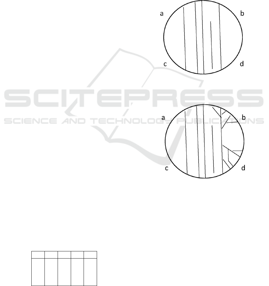
In the unexcited state filaments are chaotically ori-
ented. Let us consider an artificial plane cell with the
four zones on the cell surface: a, b, c, d, see Figure 1.
Assume that two external stimuli are transmitted from
both fronts: ab and cd. At the same time, suppose that
the protein pool of the cell activates the polymeriza-
tion and branching of filaments only in the four pos-
sible ways pictured in Figures 1, 2, 3, 4. Then the cell
can be regarded as the CNOT gate. In this gate, me-
chanical stimuli generate a filament tree building in
accordance with proteins which control treadmilling
of actin filaments and their adhesions.
Figure 1: The first possible state of reacting to two stimuli
(one from ab and one from cd): mapping 00 into 00, i.e. the
string [ab] is mapped into the string [cd].
Figure 2: The second possible state of reacting to two stim-
uli: mapping 01 into 01.
In Figure 1, there are no mechanical stimuli and,
as a consequence, there is no transmission of signal
from ab to cd or from cd to ab, i.e. there are no
filament trees and, therefore, we have a transmission
from 00 to 00. In Figure 2, we have one mechanical
stimulus at the zone b (or at the zone d) that implies a
tree building at the whole right side of the cell and we
have a transmission of signal from 01 to 01. In Fig-
ure 3, we have two mechanical stimuli at the zones
a and b (or one mechanical stimulus at the zone c)
that result a tree building at the zones a, b, and c and
from that we have a transmission of signal from 11
to 10 (or from 10 to 11). In Figure 3, we deal with
BIOSIGNALS 2016 - 9th International Conference on Bio-inspired Systems and Signal Processing
294
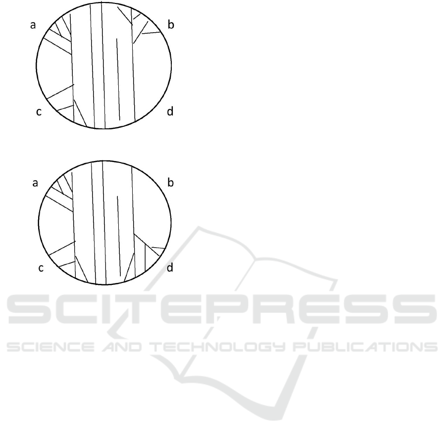
Figure 3: The third possible state of reacting to two stimuli:
mapping 11 into 10.
Figure 4: The fourth possible state of reacting to two stim-
uli: mapping 10 into 11.
one mechanical stimulus at the zone a (or with two
mechanical stimuli at the zones c and d) that causes a
tree building at the zones a, c, and d and we observe
a transmission of signal from 10 to 11 (or from 11 to
10).
3 ACTIN FILAMENTS AS
METASWARM
Highly cross-linked filaments are used in cells for
transferring the mechanical stimulus resulted by me-
chanical forces applied to cell surfaces. These forces
generate elastic stress waves which rapidly propa-
gate through actin stress fibers. Such external me-
chanical stresses can imply a diffusion of actin fila-
ment networks if filaments were uncross-linked semi-
dilute (Kas et al., 1995). So, the rotation around
their axis cause colliding with other filaments for
uncross-linked filament networks, but in the case of
cytoskeleton the mechanical stimulus is being trans-
mitted by filament strands. As a consequence, in
response to the physical force the stress fiber dis-
placement is activated in the cytoskeleton (Hotulainen
and Lappalainen, 2006; K. Hu, 2007; Ridley et al.,
2003). Some forms of that displacement which trans-
mit the external stress: fiber inertia, fiber viscoelas-
ticity, and cytosolic damping. Hence, if highly cross-
linked actin filament networks are organized in paral-
lel arrays of filaments, they become stress fibers with
the following kinds of deformation which strongly
influence on transmitting signals (ben Avraham and
Tirion, 1995; Guo and Wang, 2007; Higuchi et al.,
1995; Xu et al., 1998):
• Shear deformation. In a highly cross-linked
actin filament network both sides do not change
their lengths under shear, but the diagonals are
stretched and compressed respectively. This
stretch or compression causes a large tensional
stress in the actin filament network.
• Bending deformation. It is a curvature stress that
is a result of force that is generated by the local
extension of the material on the convex side and
compression of the material on the concave side
of the bend.
• Orientation deformation. It is a mechanical stress,
when the orientation changes.
Thus, we can consider all the possible states in the
cell deformation as a form of signal transmission by
filaments. Each deformation state is caused by an ap-
propriate mechanical force. In turn, the mechanical
signal generated by the force is transmitted in differ-
ent ways according to a kind of the cell deformation.
So, the cell can be regarded as a reversible logic gate
which has the same number of inputs (mechanical
stresses) and outputs (stress transmissions by defor-
mation). The form of the cell deformation is a form
of signal transmission. Let us examine an artificial
plane cell pictured in Figure 5. Then let us concen-
trate on the four zones on the cell surface: a, b, c,
d. Each letter runs over the two values: 1 or 0. It
has the value 1 if a mechanical stress goes through
an appropriate zone. Notice that the stress transmis-
sion depends on the cytoskeleton structure and there
may be zones, where the mechanical stress cannot go
through at all. Let us suppose that the cell pictured
in Figure 5 can have only four kinds of deformation
in transmitting mechanical signals: from Figure 6 to
Figure 9. Then this cell can be regarded as the CNOT
gate.
In this gate we assume that a compression of zone
x means the value [x] = 1 and a stretching of zone x
means the value [x] = 0. Hence, in Figure 6, we deal
with the cell deformation where all four zones a, b, c,
d are stretched and, as a result, we have a transmission
from 00 to 00. In Figure 7, zones a and c are stretched
and zones b and d are compressed and, therefore, we
have a transmission from 01 to 01. It is a bending in
the right side of the cell from b to d and vice versa. In
Toward a Computational Model of Actin Filament Networks
295
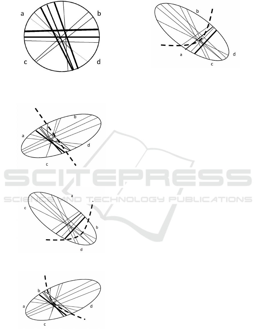
Figure 5: The artificial cell considered the CNOT gate. Its
cytoskeleton is at the normal stage without external stresses.
We assume that after stresses the string [ab] is transformed
into the string [cd] and vice versa.
Figure 6: The first possible state of the cell after one me-
chanical stress: mapping 00 into 00.
Figure 7: The second possible state of the cell after one
mechanical stress: mapping 01 into 01.
Figure 8: The third possible state of the cell after one me-
chanical stress: mapping 11 into 10.
Figure 9: The fourth possible state of the cell after one me-
chanical stress: mapping 10 into 11.
Figure 8, zones a, b, and c are compressed and zone
d is stretched and we have a transmission from 11 to
10 (or from 10 to 11). It is a bending from a, b, c to
d and vice versa. In Figure 9, zones a, c, and d are
compressed and zone b is stretched and, hence, we
have a transmission from 10 to 11 (or from 11 to 10).
It is a bending from a, c, d to b and vice versa.
Any deformation of cells is a transduction of me-
chanical stress to their neighboring cells. This allows
us to construct artificial networks uniting thousands
cells with a fixed number of neighbors for each cell.
Let us suppose that for each cell with n inputs and
k outputs we have just n + k neighbor in our actin
filament network. For instance, in the CNOT gate
we deal with 2 inputs and 2 outputs, thus, we have
4 neighbors: for each zone from a to d pictured in
Figure 5 we have just one neighbor. So, the cell de-
formation of Figure 6 implies no mechanical stress
transduction for the four neighbors of the cell. The
cell deformation of Figure 7 is a mechanical stress
transduction for the two neighbors of the cell at zones
b and d. The cell deformation of Figure 8 is a me-
chanical stress transduction for the three neighbors of
the cell at zones a, b, and c. And, finally, the cell
deformation of Figure 9 is a mechanical stress trans-
duction for the three neighbors of the cell at zones a,
c, and d.
4 CONCLUSIONS
We have considered two types of actin filament net-
works as a computational substratum: branched fila-
ments (Section 2) and cross-linked filaments (Section
3). In both cases we can design reversible logic gates.
In the second case we can design actin filament net-
works with thousands cells which by their deforma-
tions transmit mechanical stresses to their neighbors.
BIOSIGNALS 2016 - 9th International Conference on Bio-inspired Systems and Signal Processing
296

ACKNOWLEDGEMENTS
This research is supported by FP7-ICT-2011-8.
REFERENCES
Adamatzky, A., Erokhin, V., Grube, M., Schubert, Th.,
Schumann, A. 2012. Physarum Chip Project: Grow-
ing Computers From Slime Mould. International
Journal of Unconventional Computing. 8(4):319-323.
Balaban, N. Q., Schwarz, U. S., Riveline, D., Goichberg,
P., Tzur, G., Sabanay, I., Mahalu, D., Safran, S., Ber-
shadsky, A., Addadi, L. et al. 2001. Force and focal
adhesion assembly: a close relationship studied us-
ing elastic micropatterned substrates. Nat. Cell Biol.
3:466-472.
ben Avraham, D., Tirion, M. M. 1995. Dynamic and elastic
properties of F-actin: a normalmodes analysis. Bio-
phys. J. 68:1231-45.
Carlier, M. F., Valentin, R. C., Combeau, C., Fievez, S.,
Pantoloni, D. 1994. Actin polymerization: regulation
by divalent metal ion and nucleotide binding, ATP hy-
drolysis and binding of myosin. Adv. Exp. Med. Biol.
358:71-81.
Chhabra, E. S., Higgs, H. N. 2007. The many faces of
actin: matching assembly factors with cellular struc-
tures. Nature Cell Biology 9:11101121.
Choi, C. K., Vicente-Manzanares, M., Zareno, J., Whit-
more, L. A., Mogilner, A. and Horwitz, A. R. 2008.
Actin and alpha-actinin orchestrate the assembly and
maturation of nascent adhesions in a myosin II motor-
independent manner. Nat. Cell Biol. 10:1039-1050.
Coluccio, L. M., Tilney, L. G. 1983. Under physiological
conditions actin disassembles slowly from the nonpre-
ferred end of an actin filament. J. Cell. Biol. 97:1629-
1634.
Fackler, O. T., Grosse, R. 2008. Cell motility through
plasma membrane blebbing. J. Cell Biol. 181:879-
884.
Furuhashi, K., Ishigami, M., Suzuki, M., Titani, K. 1998.
Dry stress-induced phosphorylation of physarum
actin. Biochem. Biophys. Res. Commun. 242:653-658.
Furukawa, R., Kundra, R., Fechheimer, M. 1993. Forma-
tion of liquid crystals from actin filaments. Biochem.
32:12346-52.
Gimona, M., Mital, R. 1998. The single CH domain of
calponin is neither sufficient nor necessary for F-actin
binding. J. Cell. Sci.
Goldmann, W. H., Guttenberg, Z., Tang, J. X., Kroy, K.,
Isenberg, G., Ezzell, R. M. 1998. Analysis of the F-
actin binding fragments of vinculin using stopped-
flow and dynamic lightscattering measurements. Eur.
J. Biochem. 254:413-419.
Guo, W. H., Wang, Y. L. 2007. Retrograde fluxes of fo-
cal adhesion proteins in response to cell migration and
mechanical signals. Mol. Biol. Cell. 18:4519-4527.
Higuchi, H., Yanagida, T., Goldman, Y. E. 1995. Compli-
ance of thin filaments in skinned fibers of rabbit skele-
tal muscle. Biophys. J. 69:1000-1010.
Holmes, K., Popp, D., Gebhard, W., Kabsch, W. 1990.
Atomic model of the actin filament. Nature. 347:44-
49.
Hotulainen, P., Lappalainen, P. 2006. Stress fibers are gen-
erated by two distinct actin assembly mechanisms in
motile cells. J. Cell. Biol. 173:383-394.
Hu, J., Matzavinos, A., Othmer, H. G. 2007. A theoretical
approach to actin lament dynamics. Journal of Statis-
tical Physics. 128(1/2):111138.
Hu, K., Ji, L., Applegate, K. T., Danuser, G., Waterman-
Storer, C. M. 2007. Differential transmission of actin
motion within focal adhesions. Science. 315:111-115.
Iwasa, J.H., and R. D. Mullins. 2007. Spatial and temporal
relationships between actin-lament nucleation, cap-
ping, and disassembly. Current Biology. 17:395406.
Kas, J., H. Strey, J. X. Tang, D. Finger, R. Ezzell, E. Sack-
mann, and P. A. Janmey. 1995. F-actin, a model poly-
mer for semiflexible chains in dilute, semidilute and
liquid crystalline solutions. Biophys. J. 70:609-625.
Pollard, T. D. and Borisy, G. G. 2003. Cellular motil-
ity driven by assembly and disassembly of actin fil-
aments. Cell 112:453-465.
Ridley, A. J., Schwartz, M. A., Burridge, K., Firtel, R. A.,
Ginsberg, M. H., Borisy, G., Parsons, J. T. and Hor-
witz, A. R. 2003. Cell migration: integrating signals
from front to back. Science. 302, 1704-1709.
Schumann, A. 2015. Conventional and unconven-
tional reversible logic gates on Physarum
polycephalum. International Journal of Paral-
lel, Emergent and Distributed Systems. DOI:
10.1080/17445760.2015.1068775 .
Steinmetz, M., K. Goldie, and U. Aebi. 1997. A correla-
tive analysis of actin filament assembly, structure, and
dynamics. J. Cell Biol. 138:559-574.
Svitkina, T. M. and Borisy, G. G. 1999. Arp2/3 complex
and actin depolymerizing factor/cofilin in dendritic or-
ganization and treadmilling of actin filament array in
lamellipodia. J. Cell Biol. 145:1009-1026.
Van Haastert, P. J. and Devreotes, P. N. 2004. Chemotaxis:
signalling the way forward. Nat. Rev. Mol. Cell Biol.
5:626-634.
Xu, J. Y., Schwarz, W. H., Kas, J. A., Stossel, T. P., Janmey,
P. A., Pollard, T. D. 1998. Mechanical properties of
actin filament networks depend on preparation, poly-
merization conditions, and storage of actin monomers.
Biophys. J. 74:2731-2740.
Toward a Computational Model of Actin Filament Networks
297
