
Modelling of Systems for Real
Joachim Fischer
1
, Birger Møller-Pedersen
2
and Andreas Prinz
3
1
Department of Computer Science, Humboldt University, Berlin, Germany
2
Department of Informatics, University of Oslo, Oslo, Norway
3
Department of ICT, University of Agder, Grimstad, Norway
Keywords: Programming, Modelling, Prescription, Description, System, Execution.
Abstract: Modelling and Programming are often used together in system development. However, typically there is a
large difference between the handling of modelling parts and the handling of programming parts. This leads
to the fact that the transition between the two is not easy, and important information is lost as well as extra
information has to be provided when combining modelling and programming. This paper shows how
modelling and programming could work together in system development.
1 INTRODUCTION
In (Madsen and Møller-Pedersen, 2010) it is argued
that one should have a combined modelling and
programming approach to system development.
Programming has some elements of modelling, e.g.
by including the properties of classes in class
hierarchies reflecting the corresponding concepts in
the domain. However, that is almost the only kind of
modelling that is supported by programming
languages; there is no support for associations
between classes, state machines have to be made by
the application of state machine patterns, and activity
modelling is far from being supported. There has been
a number of efforts to include some of these
modelling mechanisms into programming languages
(e.g. (Rumbaugh, 1987), (Bierman and Wren, 2005)).
State machines are still mainly supported by design
patterns, although some of them may be quite
advanced, and support specialization of state
machines as found in modelling languages (Chin and
Millstein, 2008). Executable modelling languages
allow the combination of modelling and
programming, but often they select only the
executable elements from an existing modelling
language, thereby limiting the expressiveness
required for modelling of systems.
In this paper we investigate the implications of
combined modelling and programming of complete
systems, including systems of systems or systems
with subsystems and components.
When considering modelling and programming in
system development, it is important to be clear about
what a ‘system’ is, and what it means to develop it by
means of modelling and programming. There are
many definitions of system, and this paper aims at
clarifying their similarities and their differences.
Interestingly enough, the modelling language
UML is intended for system modelling, but does not
define what a system is. Reference manuals for
programming languages like Java and C# are also
silent about this, probably because the main issue
with programming languages is to define what a
program execution is, independently of what role this
execution plays in a system. Executable UML
(Mellor and Balcer, 2002), (OMG, 2006) has taken
the stand of programming languages and does not
define ‘system’.
Fortunately, it is possible to have a common
understanding of what a ‘system’ is. The key is to
look at the reality of the system. In modelling
(represented by UML) there are three different
meanings of ‘system’: real world system to be
modelled, (software) system to be made, and the
model execution including objects. Correspondingly,
there are also three ways to define the concept of
‘model’.
In programming it is obvious that the program
runtime either is the ‘system’ or is part of a larger
system. This way, the aim of the programming
activity is the running system, i.e. the execution. Such
a definition of the term ‘system’ implies that it is
placed at M0 (in the OMG meta-level architecture)
and it has both structure (in terms of object structures)
Fischer, J., Møller-Pedersen, B. and Prinz, A.
Modelling of Systems for Real.
DOI: 10.5220/0005825704270434
In Proceedings of the 4th International Conference on Model-Driven Engineering and Software Development (MODELSWARD 2016), pages 427-434
ISBN: 978-989-758-168-7
Copyright
c
2016 by SCITEPRESS – Science and Technology Publications, Lda. All r ights reserved
427
and behaviour. When applied to system description in
the DELTA language (Holbæk-Hanssen et al.,
1973), see Figure 1, the System was said to be a
model of a Referent System.
Figure 1: System being model of Referent System.
We will later come to the situations where the
System Description mere describes the System.
This paper will subscribe to the idea that ‘system’
is the running program in terms of object structures
and behaviour, and that the same applies to
modelling. We show the implications of this for
combined modelling and programming.
The problem is presented in section 2. After that,
section 3 compares the understanding of ‘system’ as
it is found in modelling and programming languages.
Section 4 takes a closer look at the prescribe-relation,
and section 5 integrates the parts and proposes
mechanisms of a combined programming and
modelling language. After having discussed related
work in section 0, we finally, conclude in section 7.
2 PROBLEM STATEMENT
As computer scientists, we tend to think of systems as
software systems. However, in reality, very few
systems are pure software systems. Most systems are
embedded, meaning they combine software with
some real hardware. Even more systems are related to
some other real entities: they represent and handle
real objects, like in library systems, or they are
integrated into the daily operation of real people, like
project management systems. Pure software systems
are more an exception than the rule.
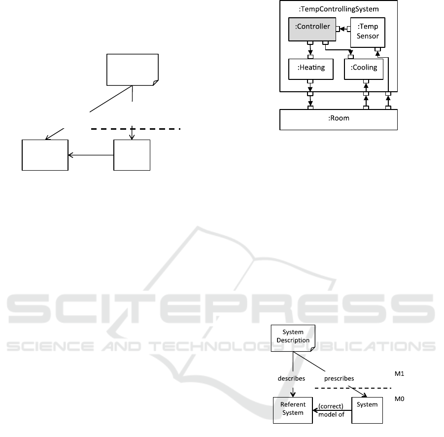
In order to discuss such systems, we look at a
(simple) example. In Figure 2:, we illustrate a
temperature control system, which has a heating
device, a cooling device, a temperature sensor and a
temperature controller. In addition, the room works as
a thermal diffusion device.
Figure 2: System with existing and new parts.
The topmost class defining the system is the class
TempControllingSystem, and illustrates how an
object of this class will look like. The
TempControllingSystem class really defines the
structure of parts connected by ports and connectors,
so is just an illustration of what any object will like.
There is only one software component in the
system, which is the controller unit. Nevertheless, we
can describe all parts of the system in e.g. UML,
maybe even using the same language features
(classes, activities, interfaces) for the Controller and
for the existing parts. The difference is not given in
the description, but in the relations to the parts of
reality (Referent System), see Figure 3:.
Figure 3: Describes and prescribes relations.
The first kind of relation, as shown in Figure 3:, is
a descriptive relation, which is normally used for the
existing parts that are not software. Here, the System
Description is describing a real part that has
behaviour in itself. The behaviour is given by its
physical construction and thereby also by the laws of
nature. However, the System Description is also
prescribing a behaviour, which is given by the
semantics of the language used for the description
(here UML). The aim in this situation is to have a
description that is faithful to the reality, in other
words a description that prescribes a system that is
equivalent to the reality on some level of abstraction.
If this is the case, the prescribed system is a model of
System
Description
M1
M0
SystemReferent
System
model
of
describes
describes/
prescribes
MODELSWARD 2016 - 4th International Conference on Model-Driven Engineering and Software Development
428

the original system. This matching between model
and reality is the core of the scientific method, where
we run experiments and check if the outcomes of the
tests match in both cases.
For the software parts no reality exists, which
leads to the second kind of relation. The descriptions
of these prescribe a (new) reality, which cannot be
compared with something existing. Typically, in this
situation, there would be some mental reality we
could try to match against, but this is less feasible than
the check against reality. This brings us back to the
situation in Figure 1.
Note that in general the issue illustrated by this
example (Figure 2:) is the architecture of systems. A
special case is when all parts of the systems are new.
In any case we would like to express the constraints
expressed by the architecture specification of the
system (system integrity): parts of the systems only
communicate via ports and connectors and they do
this according to the provided and required interfaces
of the ports.
Modelling languages readily support the kind of
description in Figure 2:, while the best way to make
the Controller part is by programming it, eventually
by using state machine supported programming. Still,
there will be at least two artefacts: the specification of
architecture in Figure 2: and an implementation of the
Controller part in some programming language. The
same is the case in an Architecture Description
Language (ADL) (Clements, 1996) or in languages
especially made for this purpose as e.g.
(Balasubramanian et al., 2005). In addition there will
be some configuration giving the binding between the
program and the existing parts. Having separate
architecture specifications and implementations of
parts makes it difficult to ensure system integrity.
The question is if the use of a combined modelling
and programming language will improve this
situation. In order to find this out, we will look into
how modelling and programming languages support
the specification of systems (including architecture of
systems).
3 SYSTEMS
3.1 Systems in UML
In the following we will cover what the main
modelling language, UML, has to say about ‘system’.
As we learned from the introduction, ‘system’ may
mean three different things: (1) a system to be made,
(2) a real world system, and (3) a running system. In
the first two cases, we consider the Referent System,
while in the third case it could be either the model
execution in case of executable models or the
program execution in case the model is translated to
some programming language. Note that in this section
we use the term ‘model’ for the System Description,
as this is the way the term is used in UML.
In the following excerpts from the current UML
specification ‘system’ is meant to be the running
system, either by executing an executable model or by
executing a program that is generated from the model:
According to the UML specification, the objective of
UML is to “provide system architects, software
engineers, and software developers with tools for
analysis, design, and implementation of software-based
systems”. “For a planned system, the model may
represent a specification of how the system is to be
constructed and behave”. “The execution of behaviors
within a modelled system may result in the creation and
destruction of objects within that system.” “A
Component can always be considered an autonomous
unit within a system or subsystem.” “When testing is
performed, the traces of the system can be described as
interactions and compared with those of the earlier
phases”.
In the following excerpts ‘system’ is meant to be the
Referent System. Note that a Referent System may be
a system in terms of a running system, for which a
model is needed:
“A model is always a model of something. The thing
being modelled can generically be considered a system
within some domain of discourse.” “For an existing
system, the model may represent an analysis of the
properties and behavior of the system.” “A Model is a
description of a system, where ‘system’ is meant in the
broadest sense and may include not only software and
hardware but organizations and processes.”
In the following excerpts ‘system’ can be Referent
System or running system:
“The execution of an Action represents some
transformation or processing in the modelled system, be
it a computer system or otherwise.” “A UML model
consists of three major categories of model elements,
each of which may be used to make statements about
different kinds of individual things within the system
being modelled_...” “For example, for a model of
factory processes, the execution scope may encompass
the execution of those processes within a single factory,
while, for a model of a software program, the execution
scope will correspond to a single execution of that
program.”
“Different Models can be defined for the same system,
...”
The last citation says that we cannot really compare
models and programs. A program is always the source
of a program execution, while some models may just
describe the system from different viewpoints.
However, when we later look at Executable UML, a
Modelling of Systems for Real
429

model is what is executed and thereby corresponds to
a program.
When it comes to how a system is described, first
of all it is described by a Model, which is a kind of
Package. A Package will typically contain a number
of class specifications, but a Model package
specification does not tell what the starting point of a
system is. It could be like for programs in e.g. Java or
C#, where the starting point is the execution of a
special method Main in one of the classes, or it could
be an object of one of the classes in the Model
package. However, UML does none of these. It does
not help to use the predefined stereotype
SystemModel on the Model package, as this just
indicates that the Model Package contains a number
of models of the same system. When it comes to
subsystems, the picture is different. Subsystem is a
predefined stereotype on Component, and
Component is a special Class, so it would be possible
to have the topmost element be an object of one of
these, although it would be strange for the topmost
element to be a component with stereotype
Subsystem. It would have been more useful to have
stereotype System; the placement of a Component
with stereotype System could tell whether it is the
topmost or a subsystem. The topmost system
component cannot be inferred as the one with
subsystems, as a SystemModel may have a number of
Models, each with a top component with subsystem
components.
One may ask why Composite Structure (that
applies to both Class and Component) is not used to
specify subsystems. That way it has been done for
years in SDL (ITU, 2011) with Blocks consisting of
Blocks, with a topmost System Block. A similar setup
is used in ROOM (Selic et al., 1994) and in ADLs.
3.2 Systems in Programming
Almost no programming language definition has any
relation to a system concept; the only exception
known to the authors is BETA
(Madsen et al., 1993),
where ‘a program execution is regarded as a physical
model simulating the behaviour of either a real or imaginary
part of the world’
, ‘model’ being the system generated
as part of a program execution. Programming
language definitions are mostly concerned with what
program executions are, but not what they are used
for. Program execution in different languages is
represented differently:
1) Java (Gosling et al.) , C# (Hejlsberg et al.,
2003): by an invocation of a (by convention) static
method named Main in a class;
2) Simula (Dahl and Nygaard, 1965), BETA
(Madsen et al., 1993), Python,
(PythonSoftwareFoundation, 2015)
, Grace (Black
et al., 2013) , …: by an outermost (singular) object.
3.3 Systems in Executable UML
The scope of the specification of executable UML is
the selection of a subset of the UML 2 meta-model
that provides a shared foundation for higher-level
UML modelling concepts, as well as the precise
definition of the execution semantics of that subset:
“Given its fundamental nature, the subset assumes the
most general type of system, including physically
distributed and concurrent systems with no assumptions
about global synchronization.”
This seems to indicate that it is possible to make full
system descriptions, but the subset of UML
constructs available in executable UML corresponds
to the constructs available in a programming language
with support for associations and actions in terms of
activities.
“For example, composite structure and simple state
machines are considered moderately used.”
– and
therefore not included in Executable UML. A
description like the one in Figure 2: is therefore not
possible in executable UML.
The similarity between programs and executable
models is that the language definitions are purely
concerned with properties of executions, and not the
relation of the runtime elements to elements of the
Referent System. It is left to the users of the languages
to establish these relations in their minds.
4 PRESCRIPTIONS
The describes-relation is quite lightweight, in that it
just provides an abstraction of some kind. It is not
attached with a fixed semantics. The prescribes-
relation, however, has semantics and is central to
programming.
4.1 Definition, Use and Runtime
The prescribes-relation follows a general pattern of
definition and use, (Bézivin and Gerbé, 2001). Here,
the prescription is the definition, and system is the
use. In terms of programming, the prescription relates
to compile (definition) time, i.e. when the program is
made. At this time, the program is changeable by
tools. After compile time, the program is considered
fixed, and it may then be used as the prescription of
all possible structures that may exist during run time.
MODELSWARD 2016 - 4th International Conference on Model-Driven Engineering and Software Development
430

Runtime (use) is the selection of possible
structures defined by the program, as snapshots of the
running program. Most often, there are tools between
these two phases, the most obvious one being a
compiler, even generating intermediate forms of
definitions (e.g. assembler code or machine code). In
case of structure, use entails all the possible structures
at runtime. In case of behaviour, use means all the
possible runs.
This definition-use pattern is a very basic pattern
for programming. The connection between definition
and use is given by a semantic function, associating
the definition with a set of possible uses.
4.2 Languages
The definition-use pattern becomes very obvious
when we look at formal languages. A formal language
is most often given by three aspects (Mu et al., 2010):
Structure (abstract syntax), giving the constructs
of the language as well as their relations to each
other. Also restrictions in the use are handled
here (constraints). A typical way to define
structure is a MOF-metamodel with OCL-
constraints (OMG, 2006), or a grammar
defining an abstract syntax with constraints
given by grammar attributes.
Notation (concrete syntax), defining how to
present the specifications in the language. The
concrete syntax can be textual or graphical or a
combination of both. A typical way to define the
textual syntax is a context-free grammar.
Semantics (meaning), defining what
specifications mean. As we are relating
modelling and programming, we will focus on
execution semantics.
A language is itself a definition that is used when
creating a program of that language, which again is
used in the execution of the program. This leads to
three levels: the level of the language, the level of the
program, which is formed according to the rules of
the language, and the level of the run, which is formed
according to the program. We can group these levels
into a hierarchy such that it is also possible to describe
languages themselves using other languages (so-
called meta-languages). OMG has formalized this
with a four-level hierarchy of abstractions. The
lowest level, called M0, is for objects in terms of a
run. The next level (M1) is devoted to the programs
and specifications that describe those objects. On top
of M1 there is a language level M2 describing how
programs and specifications are formed. The
languages Java and UML would be examples here.
Finally, the architecture is closed with a level M3
(meta-language) that is supposed to both describe
languages at M2 as well as describing itself. MOF is
a typical example of a meta-language.
Definition and use appear between two adjacent
levels, where the higher one has the definition role
and the lower one has the use role. This way, the same
entity can have the use role in one context and the
definition role in another context.
4.3 Traces
As Figure 1 shows, the prescription (definition) is not
the entity that models reality. Rather, the use (System
in Figure 1) is modelling reality. What is the use of a
typical program or description? Here, we come back
to the distinction between structure and behaviour. At
runtime, we will have structures and behaviours, and
for dynamic systems both aspects are important.
When looking at a match between real system and
constructed system, it is essential to know what to
compare. In a typical open real system, the behaviour
can be understood as a trace, which depends on the
external inputs to the system. In our example from
Figure 2:, the external inputs are the connections to
the room, i.e. heat, cool, and temperature. Apart from
those, the system is self-contained. Based on this
observation, we consider a system to be a function
from inputs to traces, or a set of traces, when the
traces include the inputs. As (Madsen and Møller-
Pedersen, 2010) already state, the model of such a
real system is again an execution, i.e. a function from
input to trace.
A trace is a sequence of snapshots of system
states, normally given with respect to the level of
granularity of the description. It has become
customary to understand such snapshots as purely
structural, showing the objects existing at a certain
snapshot. This is exactly the idea of UML
InstanceSpecification. A similar approach is used in
languages like CCS (Milner, 1980.) and CSP (Hoare,
1978).
4.4 Machines
Both programming and modelling are using
descriptions of reality. Such a description is just a text
or a combination of diagrams and text formed
according to the definition of its language. It does not
come to life unless it is placed in a proper
environment. We call such an environment a machine
or a platform. In our examples, the referent system is
typically ‘run’ in the reality (machine), while the
system itself is run in a computer or similar device. A
machine can be real or virtual, and often the machine
Modelling of Systems for Real
431
relates to a language. A machine is special for its
language, but it is also general in the following two
properties:
A machine allows creating structures of objects
or physical entities. Everything that a machine
can represent fits into such a structure. Note that
reality itself does not have such a structure, but
humans impose structure onto it.
A machine allows changing structures using
behaviour primitives (instruction set) that can be
combined.
So far, we have used the machines “reality” (for
referent systems), “computer” (for systems), and
“human” (for imaginary referent systems). When
running a description on a machine, physical realities
lead to the run and enable execution behaviour as well
as structure creation.
When inspecting the execution on a machine (e.g
by some kind of debugger), we may inspect states and
state changes, either using the real machine
understanding, the language understanding, or the
program understanding.
5 COMBINED SPECIFICATIONS
The notions of modelling and programming are not
used consistently within computer science. Based on
the previous sections, we propose the following
distinction:
Modelling is the activity to describe a real (part of
a) system using a language that implies semantics for
this description. The model is correct if it matches the
real system (Figure 3:).
Programming is the activity to prescribe a new
(part of a) system using a language with a well-
defined execution semantics (Figure 1).
It is obvious, that the above definition allows
using (executable) UML for programming as well as
Java for modelling. In fact both these cases appear in
reality, maybe not as cleanly as described here. Some
aspects of programs describe real phenomena, like
e.g. persons and seats in a reservation system.
Whenever a software system is tested, the
environment of the system is simulated using some
more or less advanced signal generators for the
environment. This is essentially a modelling activity.
In testing it is also asked how well the test cases
reflect the reality of the environment, thus making the
modelling complete. In cyber-physical systems it is
common to use mathematical methods to reason
about the complete system including real parts and
constructed parts.
In a combined modelling and programming
language both of these two aspects of the
specification will be supported (see Figure 2:), and if
something like this is part of a combined modelling
and programming language, the implication is that a
specification will be just one artefact instead of a
structural specification in a modelling language, a
program in a programming language and a
configuration file. The existing parts (white) of the
system that are already implemented only need to be
described, while the new parts (grey) have to be
prescribed.
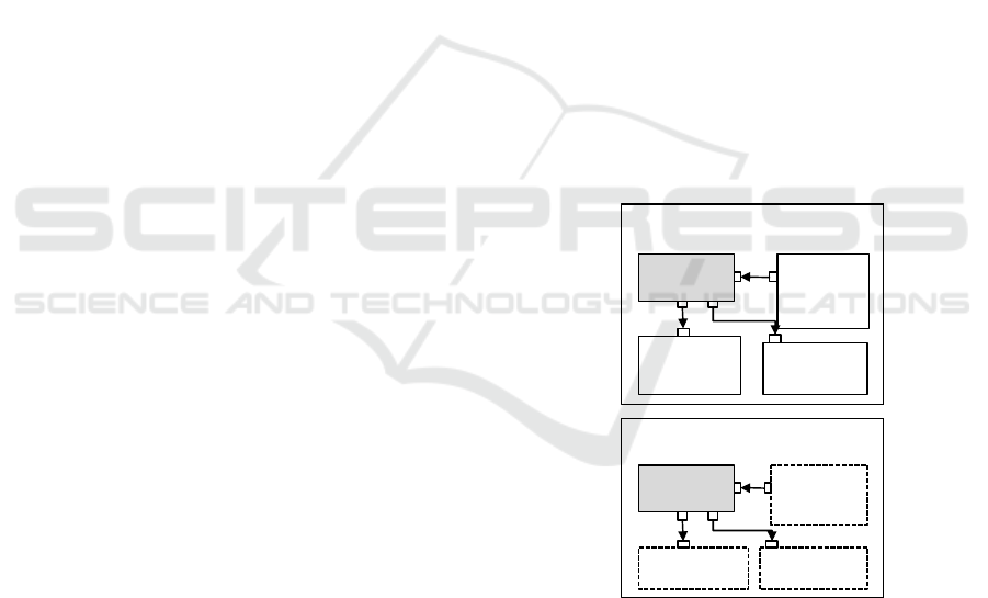
Given the description in Figure 2: in a combined
modelling and programming language, it is possible
to program the Controller, and then either connect this
to simulations of the other parts, or connect to real
devices, see Figure 4:.
In Figure 4: we show two cases of using the
description given in Figure 2:. In the upper part, we
show how it is possible to simulate the real parts in
order to test the system before installing it. In this
case, all parts are physically represented by code,
which is run on some virtual machine. In the lower
part, we show how it is possible to use the real devices
directly and connecting the control unit to them,
which amounts to the final application scenario.
Figure 4: Simulating or Running the Specification.
When the Controller is ready for being deployed,
it may form the controller part of several different
systems, where the controller is connected to different
sets of real devices; see for example Figure 5: for one
of these.
All these systems relate to the same prescription, and
therefore also to the same referent system, which is in
this case in the head of the developer. All of them
have runs and they are therefore different systems.
However, in a mathematical sense they are equivalent
RealCooling:RealHeating:
:Controller RealTemp
Sensor:
MyHouseForReal:
TempControllingSystem
Simulated
Heating:
:Controller
MyHouseForTesting:
TempControllingSystem
Simulated
Temp
Sensor:
Simulated
Cooling:
MODELSWARD 2016 - 4th International Conference on Model-Driven Engineering and Software Development
432
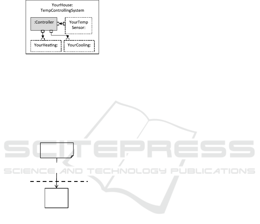
on the level of abstraction as defined in the
description. Of course, as they are connected to
different real situations, they would not be equivalent
in their connections.
Figure 5: Deploying the Controller in two Houses.
For our purpose, it is important to cover behaviour
aspects in the snapshots. A language like Java
indicates the current execution position with the
program counter, and it will also at runtime have a
whole runtime environment capturing the state of
execution. All this information must be part of a
snapshot.
Note that a snapshot is an example of a description
of a (running) system, as snapshots are not
prescriptive.
Figure 6: Snapshots describe (running) systems.
While UML as a representative for modelling
languages has means (although rudimentary) for
describing snapshots by means of instance
specifications, debuggers for programming languages
do not present snapshots in a notation that has
anything to do with the programming language.
In a combined modelling and programming
language we would have snapshots covering both
structural aspects (with state information) like
InstanceSpecification in UML and behavioural
aspects (like state of execution in a debugger). As a
snapshot is a kind of description, one would expect
that both of these aspects could be expressed in the
language.
6 RELATED WORK
As mentioned above, ADLs do not combine
architectural descriptions with behaviour
specifications of the systems.
Already in the 1988 version SDL (ITU, 2011) had
support for modelling of systems with structure and
behaviour, ensuring system integrity. However, the
behaviour part of the language is difficult to use; most
tools therefore support the embedding of program
code in SDL descriptions.
The same is the case with ROOM, see (Selic et al.,
1994). In 1999 (Rumpe et al., 1999) assessed the
usefulness of ROOM+UML as an ADL, concluding
that instead of including the architecture descriptions
of ROOM into collaboration diagrams, they should
rather be part of classes.
Much of the critique was met in UML2.0 (OMG,
2003) with composite structures for both classes and
components, as components are special classes.
However, as covered above the notion of system and
subsystem was not revised correspondingly.
ArchJava is an attempt to make components with
ports and connectors available in Java, (Aldrich et al.,
2002). ArchJava is an extension of Java with support
for components, ports and connectors with languages
constraints that makes it possible to achieve system
integrity.
7 SUMMARY
System development is concerned with systems that
contain existing parts and new parts. Often, the
development activity is confined with only one of the
parts, and therefore it is not complete. We propose a
complete understanding of the notion of system as the
basis for system development. In order to achieve this
complete understanding, a combination of
programming and modelling must be applied.
Programming and modelling are two ways of
relating to reality. In this paper, we have compared
them. Both of them describe a referent system, which
is real in terms of modelling and which is imagined in
terms of programming. Both of them prescribe a
system at different levels of precision.
The approach has been demonstrated on a simple
example.
Snapshot
M1
M0
System
describes
Modelling of Systems for Real
433

REFERENCES
Aldrich, J., Chambers, C. & Notkin, D. 2002. Archjava:
Connecting Software Architecture To Implementation.
Icse ’02 Orlando, Fl, Usa.
Balasubramanian, K., Balasubramanian, J., Parsons, J.,
Gokhale, A. S. & Schmidt, D. C. A Platform-
Independent Component Modeling Language For
Distributed Real- Time And Embedded Systems. 11th
Ieee Real-Time And Embedded Technology And
Applications Symposium,, 2005. Ieee Computer
Society.
Bézivin, J. & Gerbé, O. 2001. Towards A Precise Definition
Of The Omg/Mda Framework. 16th Annual
International Conference On Automated Software
Engineering, (Ase 2001). Ieee.
Bierman, G. & Wren, A. First-Class Relationships In An
Object-Oriented Language. Ecoop 2005 - European
Conference On Object-Oriented Programming, 2005
Glasgow. Springer Verlag.
Black, A. P., Bruce, K. B. & Noble, J. 2013. The Grace
Programming Language Draft Specification Version
0.3.1303. Available: Http://Gracelang.Org/Application
s/Home/.
Chin, B. & Millstein, T. 2008. An Extensible State Machine
Pattern For Interactive Applications. In: Vitek, J. (Ed.)
Ecoop 2008.
Clements, P. C. 1996. A Survey Of Architecture
Description Languages. Eighth International Workshop
On Software Specification And Design. Germany.
Dahl, O.-J. & Nygaard, K. 1965. Simula—A Language For
Programming And Description Of Discrete Event
Systems. Oslo: Norwegian Computing Center.
Gosling, J., Joy, B., Steele, G. & Bracha, G. 2005. The Java
Language Specification. Addison-Wesley, Third
Edition.
Hejlsberg, A., Wiltamuth, S. & Golde, P. 2003. The C#
Programming Language, Addison-Wesley.
Hoare, C. A. R. 1978. Communicating Sequential
Processes. Communications Of The Acm, 21.
Holbæk-Hanssen, E., Håndlykken, P. & Nygaard, K. 1973.
System Description And The Delta Language. Oslo:
Norwegian Computing Center.
Itu 2011. Z.100 Series, Specification And Description
Language Sdl.
Madsen, O. L. & Møller-Pedersen, B. 2010. A Unified
Approach To Modeling And Programming. Models
2010, 2010 Oslo. Springer.
Madsen, O. L., Møller-Pedersen, B. & Nygaard, K. 1993.
Object-Oriented Programming In The Beta
Programming Language, Addison Wesley.
Mellor, S. J. & Balcer, M. J. 2002. Executable Uml: A
Foundation For Model-Driven Architecture., Addison-
Wesley.
Milner, R. 1980. Robin Milner: A Calculus Of
Communicating Systems, Springer Verlag.
Mu, L., Gjøsæter, T., Prinz, A. & Tveit, M. S. 2010.
Specification Of Modelling Languages In A Flexible
Meta-Model Architecture. Software Architecture, 4th
European Conference, Ecsa Copenhagen, Denmark.
OMG 2006. Meta Object Facility (Mof) Core Specfication.
Version 2.0 (Available Specification) Omg Document:
Formal/06-01-01.
Pythonsoftwarefoundation. 2015. Python [Online].
Available: Https://Www.Python.Org/.
Rumbaugh, J. Relations As Semantic Constructs In An
Object-Oriented Language. In: Meyrowitz, N., Ed.
Oopsla'87 – Object-Oriented Programming, Systems
Languages And Applications, 1987 Orlando, Florida,
Usa. Acm Press.
Rumpe, B., Schoenmakers, M., Radermacher, A. & Schürr,
A. Uml+Room As A Standard Adl? 5th International
Conference On Engineering Of Complex Computer
Systems, 1999.
Selic, B. 2004. The Subsystem: A Curious Creature. Ibm
Rational Technical Library [Online]. Available:
Http://Www.Ibm.Com/Developerworks/Rational/Libr
ary/2107.Html.
Selic, B., Gullekson, G. & Ward, P. T. 1994. Real-Time
Object-Oriented Modeling, John Wiley & Sons Inc.
MODELSWARD 2016 - 4th International Conference on Model-Driven Engineering and Software Development
434
