
Pixel-wise Ground Truth Annotation in Videos
An Semi-automatic Approach for Pixel-wise and Semantic Object Annotation
Julius Sch
¨
oning, Patrick Faion and Gunther Heidemann
Institute of Cognitive Science, University of Osnabr
¨
uck, Osnabr
¨
uck, Germany
Keywords:
Semantic Ground Truth Annotation, Video Annotation, Polygon Shaped, Semi-automatic.
Abstract:
In the last decades, a large diversity of automatic, semi-automatic and manual approaches for video segmen-
tation and knowledge extraction from video-data has been proposed. Due to the high complexity in both
the spatial and temporal domain, it continues to be a challenging research area. In order to develop, train,
and evaluate new algorithms, ground truth of video-data is crucial. Pixel-wise annotation of ground truth is
usually time-consuming, does not contain semantic relations between objects and uses only simple geometric
primitives. We provide a brief review of related tools for video annotation, and introduce our novel interactive
and semi-automatic segmentation tool iSeg. Extending an earlier implementation, we improved iSeg with a
semantic time line, multithreading and the use of ORB features. A performance evaluation of iSeg on four
data sets is presented. Finally, we discuss possible opportunities and applications of semantic polygon-shaped
video annotation, such as 3D reconstruction and video inpainting.
1 INTRODUCTION
If YouTube would be watching and annotating all up-
loaded videos manually and in real time, 18, 000 op-
erators would be necessary. This number is based on
the official press statistics of YouTube (2015), where
YouTube stated that 300 hours of video are uploaded
every minute just to their platform. Thus, knowl-
edge extraction, knowledge acquisition, and seman-
tic scene understanding from video-data is important.
Detection of concepts such as “person”, “building” or
“car” is possible by current automatic content analy-
sis in many cases, provided there is no occulsion (Da-
siopoulou et al., 2011; H
¨
oferlin et al., 2015; Tanis-
aro et al., 2015). So manually created annotations be-
come ever more important because they are necessary
as ground truth for the development of algorithms—
both for training and evaluation.
In the architecture of video visual analytics (VVA)
by Tanisaro et al. (2015) the computer assists the user
on the two lowest levels of the reasoning process: the
extraction of meaningful artifacts and the assessment
of situations. All annotation methods for video and
image data, mentioned by Dasiopoulou et al. (2011),
do no use such interactive techniques. Following
the VVA architecture of combining the computational
power of a computer with the high level abilities of
the human user, we (Sch
¨
oning et al., 2015) designed
iSeg. Through iSeg’s semi-automatic design the qual-
ity of the results increases significantly with a slight
improvement in the annotation speed.
While current freely available video annotation
tools (Doermann and Mihalcik, 2000; Wu et al., 2014;
Yao et al., 2012) usually provide only simple geomet-
ric primitives like rectangles and ellipses, iSeg pro-
vides polygon-shaped areas—a significant improve-
ment in video annotation. Another problem of cur-
rent tools is that they provide no or little support for an
easy concurrent annotation of several frames. Further,
they do not provide means to enter semantic inter-
object knowledge, like “the blue car is in front of the
yellow house”.
To overcome these drawbacks, we propose an in-
teractive, semi-automatic process based on polygons.
Arbitrary polygonal shapes can be annotated, and the
user is actively asked for interaction if the result of
the automatic annotation process seems to be incor-
rect. Compared to a previous version of iSeg, we ac-
complished a major improvement of the user inter-
face (UI): The semantic time line provides intuitive
and easy to use interaction metaphors for authoring
semantic knowledge. Another improvement has been
made in the user experience, where efficient multi-
threading implementations minimize the system’s re-
sponse time and allow the user to interact with the
system, while time-consuming tasks run on a differ-
690
Schöning, J., Faion, P. and Heidemann, G.
Pixel-wise Ground Truth Annotation in Videos - An Semi-automatic Approach for Pixel-wise and Semantic Object Annotation.
DOI: 10.5220/0005823306900697
In Proceedings of the 5th International Conference on Pattern Recognition Applications and Methods (ICPRAM 2016), pages 690-697
ISBN: 978-989-758-173-1
Copyright
c
2016 by SCITEPRESS – Science and Technology Publications, Lda. All rights reserved

ent process. Finally, we were able to reduce the pro-
cessing time needed for automatic contour tracking
by using ORB features instead of SIFT features.
2 STATE OF THE ART
Using criteria like in- and output formats, metadata
types, as well as granularity, localization, and expres-
sivity of the annotations, Dasiopoulou et al. (2011) re-
viewed and compared several image and video anno-
tation tools. According to their review, four of seven
image annotation tools provide polygon-shaped anno-
tations, but in contrast only one of seven video anno-
tation tools provides polygon-shaped annotations, the
Video and Image Annotation tool (VIA) (Multimedia
Knowledge and Social Media Analytics Laboratory,
2015). But during testing the latest version VIA (Ver-
sion 1.0s), we were able to annotate frames by rect-
angular areas only. Unfortunately, we were unable to
annotate polygon-shaped areas, because we did not
find any other non-rectangular annotation marker in
the user interface. We also noticed that VIA only dis-
plays a clipped region of a FullHD video.
In 2000, Doermann and Mihalcik (2000) devel-
oped the Video Performance Evaluation Resource
(ViPER). An automatic 2D propagation of the anno-
tated object can be used to speed up the annotation
process. This tool is still quite popular, due to its
properly defined and specified XML output format.
The specified XSD schema of the XML output is still
a basic of a straightforward usage of ViPER’s annota-
tions for other applications.
Wu et al. (2014) designed the Semi-Automatic
Ground Truth Annotation tool (SAGTA) for the rect-
angular annotation of pedestrians in scenes. Its semi-
automatic process relies on the assumption of 3D lin-
ear motion supported by ORB feature matching. It re-
duces the number of manually annotated frames. Be-
cause of the 3D linear motion assumption, the input
video for SAGTA must be taken by fixed cameras, e.g.,
surveillance cameras.
Using the crowd for performing annotations in
real-time, the Vannotea System (Schroeter et al.,
2003) pool the resources of several users. This
still exotic approach enables multiple users to in-
dex, browse, annotate and discuss the same video se-
quences at the same time.
3 iSeg
Based on the architecture of VVA, iSeg focused on
a semi-automatic process that puts the user into the
loop. As shown in Figure 1, iSeg consists of eight
main process blocks. Two blocks of these eight are
obligatory and must be processed in a specific order—
in Figure 1 marked with a white headline—but the re-
maining process blocks—in Figure 1 marked with a
gray headline—can be executed by the user in any se-
quence. These blocks can also be repeated as often as
necessary until the intended annotation is achieved.
1
The first obligatory process block is the selection
of the video or the image sequence by the user. The
second obligatory process block is marking one or
more areas of interest (AOI) in at least two frames
by the user, e.g., in the first frame the AOI appears
and in the last frame the AOI disappears. In addi-
tion, the user can optionally identify the AOI in every
frame between these two frames. The following pro-
cess steps from the automatic morphing process of the
polygon geometry via the interactive semi-automatic
AOI fitting to the export of the resulting annotations
are now described in detail.
3.1 Polygon Morphing
Since the user is identifying the AOI only on a few
frames, the algorithm has to estimate the positions and
the contours of the AOI on the intermediate frames.
For convenience, the user can use polygons with vary-
ing numbers of vertices on different frames. Contours
of common AOI can be both convex or concave, are
intersection free, and, for simplicity, holes in the AOI
are omitted. Thus the task is to morph two simple
polygons, i.e., non self-intersecting ones with differ-
ent numbers of vertices. Additionally, it is important
that all intermediate polygons are also simple poly-
gons, since they resemble the contours as well.
There are several existing algorithms in the lit-
erature concerning polygon interpolation. One of
the first is the Cobos and Peetre (1991) polygon in-
terpolation, unfortunately, it works only with con-
vex polygons. Alt and Guibas (1996) gave a short
overview of other approaches but already stated that
morphing simple polygons is rather complex when
all intermediate polygons need to be simple as well.
Most approaches, especially those matching polyg-
onal chains, will usually result in self-intersecting
intermediate polygons. There is also a promising
method by Gotsman and Surazhsky (2001) on morph-
ing even polygons with holes, but it requires the poly-
gons to have the same number of vertices. So, given
our constraints, the problem is non-trivial. In addi-
tion, we found that approaches with a direct vertex-to-
vertex mapping will often result in artificial rotation
1
Demonstration video of the annotation process iSeg
https://ikw.uos.de/∼cv/publications/icpram15
Pixel-wise Ground Truth Annotation in Videos - An Semi-automatic Approach for Pixel-wise and Semantic Object Annotation
691
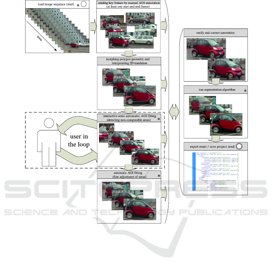
Figure 1: Process overview of iSeg’s interactive semi-automatic annotation and segmentation process. Process blocks with
white headlines are obligatory to run iSeg. Blocks with gray headlines are optional and can be used in any order at any
time. The process block interactive SIFT key point fitting actively asks for user interaction in case the automatically generated
annotations appear to be incorrect. Thus, the computer remains the “work horse” of the process, while the close cooperation
with the user allows iSeg to achieve sophisticated results. The system response time in blocks marked with “*” is minimized
using multithreading.
of the contour. However, computer vision can detect
the relative rotation of an object between frames, e.g.,
using the rotation information in the scale-invariant
feature transform (SIFT) (Lowe, 2004). Therefore,
the rotational component could be separated and ver-
tex morphing should be approximately radial. Since
none of the existing methods seemed to fit our needs,
we implemented a new, very basic form of polygon
matching to test whether the semi-automatic approach
with the aid of computer vision is viable.
Given two polygons A = {a
1
,a
2
,...,a
n
} and
B = {b
1
,b
2
,..., b
m
} we first separate out the trans-
lation component by centering the polygons on their
center of gravity. In the future, we would also like
to extract a rotation component beforehand by means
of computer vision. To cope with the problem of dif-
ferent vertex numbers, we introduce additional points
in the polygons. For every point in A there will
be an additional point on the contour of B and vice
versa, so all intermediate polygons will have n + m
points. For every point a
i
∈ A the position of the
matching additional point on the contour of B is the
point on the contour with the smallest distance to A:
match(a
i
) = argmin
c
i
∈π(a
i
)
(||a
i
− c
i
||) where π(a
i
) is
the set of closest points to a
i
on every line segment
in B. The points a
i
and match(b
j
) (as well as b
j
and match(a
i
)) will then be collected into two new
polygons according to their positions in A and B.
As a result, there are n + m points on the contour
of A and n + m points on the contour of B, where
each point from the contour of A matches to a cor-
responding point on the contour of B and vice versa.
ICPRAM 2016 - International Conference on Pattern Recognition Applications and Methods
692
b
3
b
2
b
1
a
1
a
2
a
3
a
4
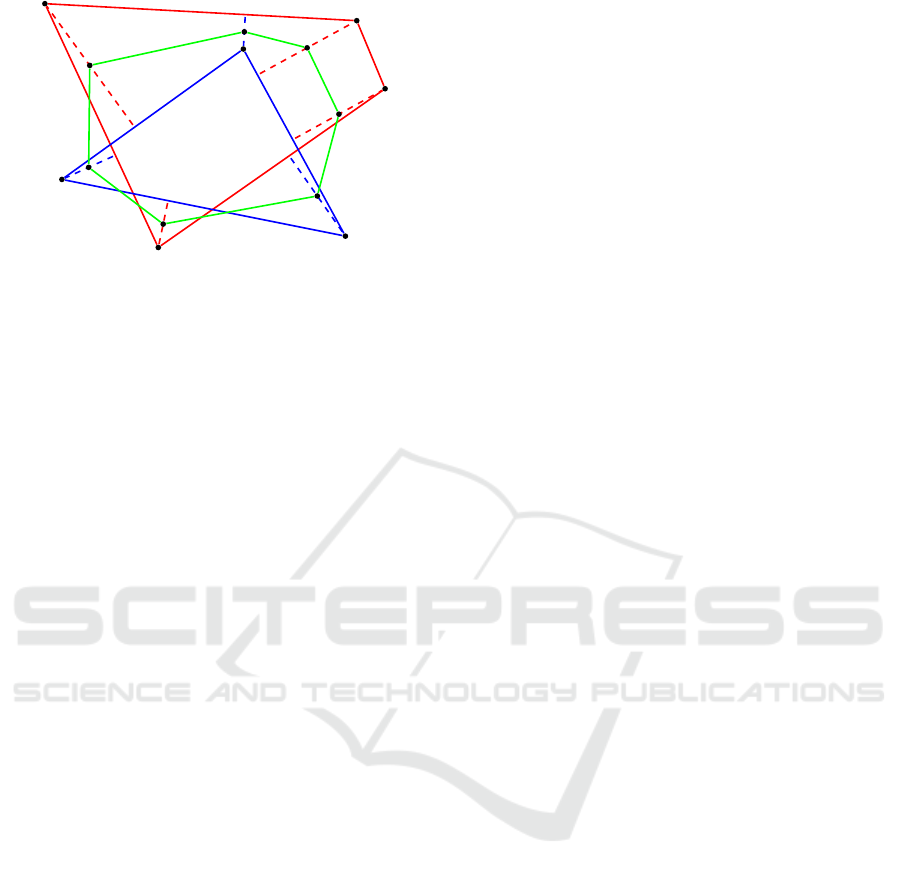
Figure 2: Visualization of polygon morphing between poly-
gon A (red) and polygon B (blue). Dashed lines indicate the
matching between each polygon point and the closest cor-
responding point on the other polygon. The green polygon
is an intermediate interpolation at t = 0.5.
Unfortunately, there can be cases where predecessor-
successor relations are violated. Checking the order
of vertices in A and B and exchanging conflicting ver-
tices can correct some of these violations. Finally we
interpolate linearly between matched points as well
as along the translation vector. A visualization of the
pure shape morphing can be seen in Figure 2.
The algorithm is very simple and straightforward.
It already works in many cases, especially when the
two polygons are not completely different in their
shape, which will be the common case in this context.
Still, it is only a “heuristic” approach and there are
problems with some polygons where the point match-
ing is not possible such that predecessor-successor re-
lations are preserved. In these cases, there can be self-
intersecting polygons on intermediate frames. Nev-
ertheless, this first approach can deal with polygons
with different numbers of vertices and in principle
also with concave polygons—although they are more
likely to cause errors. In addition, the matching of
points straight onto the closest corresponding point
does not introduce unjustified rotations. With time
complexity O(nm), the algorithm is rather fast. We
are aware that our approach is still at an early stage
and might not be adjustable to work without errors in
all situations. But due to the lack of existing methods
suiting our requirements, it is a first step into a field
with further research potential.
3.2 Interactive Semi-automatic AOI
Fitting
Within this process block the linearly interpolated in-
termediary polygons of the AOI will be adjusted to fit
the real object on each frame. This is necessary, since
the 2D-projection of the real movement of the AOI
will most likely be non-linear in reality. Therefore,
the oriented FAST and rotated BRIEF (ORB) algo-
rithm by Rublee et al. (2011) is applied to the AOI
to extract z key points F = { f
1
, f
2
,..., f
z
} of each
AOI
1
,AOI
2
,..., AOI
y
. Note, to minimize the compu-
tational cost of the ORB algorithm, only the inner
areas of the AOI are processed—the processing on
the whole image increases the computational cost sig-
nificantly. The ORB algorithm performs as well as
SIFT (Lowe, 2004), but with less computational time
(Rublee et al., 2011). Thus the system response time,
aka the “waiting time” for the user, is minimized.
All key points F are calculated for the AOI on the
current frame F
g
and for the corresponding AOI on
the next frame F
(g+1)
, highlighted with white circles
in Figure 4. Under the assumption that rotation and
scaling of the object in the AOI are negligible, the key
points from the current frame F
g
are matched with the
next frame F
(g+1)
using FLANN (Muja and Lowe,
2009). Based on the approximate nearest neighbors
matching result M
g−(g+1)
= {m
1
,m
2
,..., m
n
}, key
points f ∈ F
g
∧ f ∈ F
(g+1)
with distances M
g−(g+1)
bigger than 100 are eliminated. In case more than 10
key points of F
g
and F
(g+1)
are left after the key point
elimination, the centers of gravity of the remaining i
key points C
F
=
i
∑
c=1
f
c
for F
g
and F
(g+1)
are calcu-
lated, shown as blue points in Figure 4(a). Further-
more, the center of gravity C
AOI
=
n
∑
c=1
a
c
of the AOI
polygon in the current and next frame are computed,
in Figure 4(a) marked with a gray point. Next the vec-
tor ~v = (C
F
− C
AOI
) between the center of gravity of
the key points and the center of gravity of the AOI
is determined. If rotation and scaling are negligible,
the vector ~v on the current and on the next frame are
approximately the same. Under the assumption that
the center of gravity of the key points C
F
is congru-
ent to the non-linear movement of the object, a vector
can be used to adjust the position of the AOI. There-
fore, the new center of gravity of the AOI C
0
AOI
in
the next frame is calculated concerning to vector ~v of
the current frame. The new center C
0
AOI
is marked
as a red point in Figure 4(a). With the difference
∆ = C
AOI
− C
0
AOI
an affine transformation of the AOI
using homogeneous coordinates is performed. As a
consequence, the AOI is transformed and the non-
linear motion of the AOI is taken into account.
As shown as in Figure 4(b), if less than 10 key
points as element of F
g
and F
(g+1)
are left after the
elimination, the algorithm actively asks the user for
interaction. The user can now adjust the polygon
AOI with three intuitive metaphors described in Sec-
tion 3.4 and continue the interactive semi-automatic
AOI fitting process. The main reasons for less than
Pixel-wise Ground Truth Annotation in Videos - An Semi-automatic Approach for Pixel-wise and Semantic Object Annotation
693
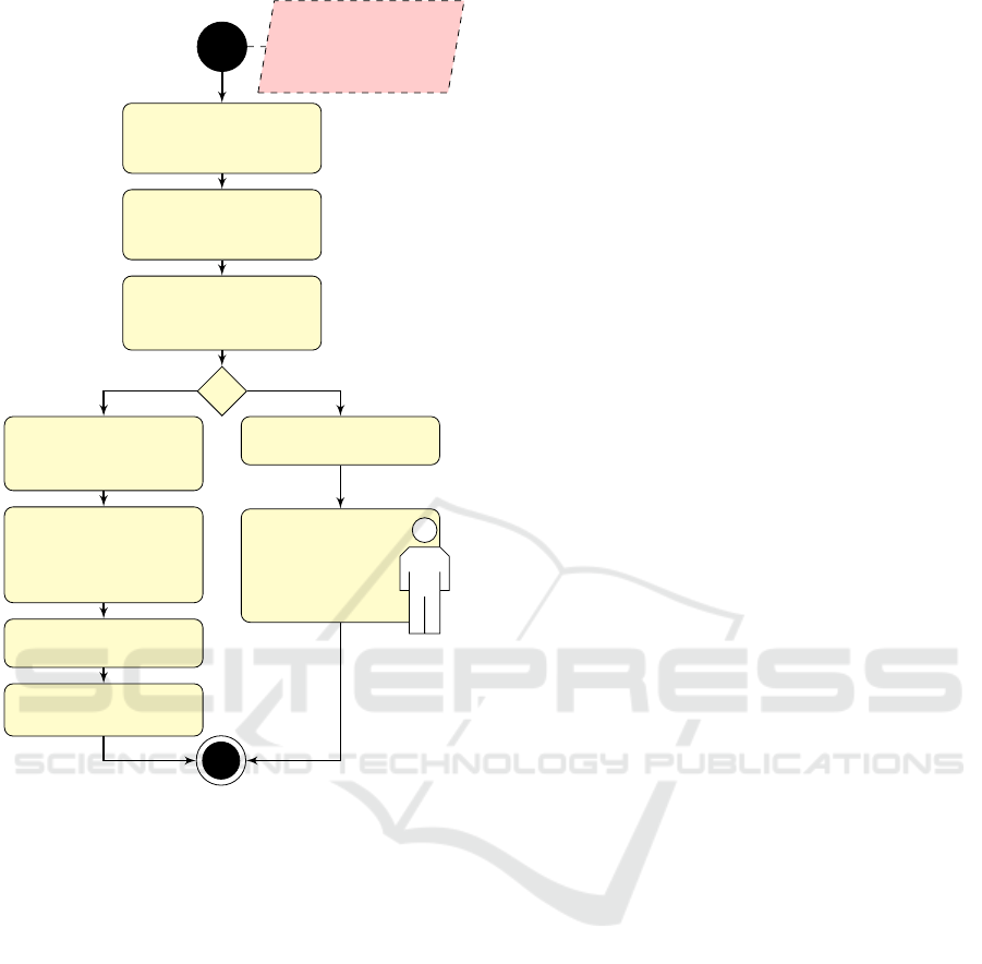
input:
– current frame and
– next frame
incl. their AOI
calculate key points
in the AOIs of current
and next frame
match key points
between current
and next frame
eliminate matches
with distances
bigger than 100
calculate centers
of gravity of key
points and AOIs
actively ask for
user interaction
calculate vector
between centers
of gravity of key
points and AOIs
interactive
adjust AOI of
next frame
calculate a delta vector
from the vectors
adjust AOI of next
frame by delta vector
[#matches > 10] [false]
Figure 3: Activity diagram of the interactive semi-
automatic AOI fitting. It has to be repeated until all AOI
are adjusted.
10 key points remaining are that the size of the AOI is
too small, the AOI is occluded, the AOI mainly con-
tains textureless areas, or the object in the AOI has
changed between two frames.
This process of close cooperation between com-
puter and user is continued until all AOI are detected
that cannot be computed automatically.
3.3 Automatic AOI Fitting
The automatic AOI runs the same algorithm as the
semi-automatic AOI, see Figure 3, but with a slight
difference. In case less than 10 key points are left af-
ter the elimination, the next frame remains unchanged
and the process will be continued. The main idea
of this process block is that it is performed after the
interactive semi-automatic AOI fitting is performed
once and has detected all non-automatically com-
putable AOI. On that condition, the automatic AOI
fitting increases the accuracy of the result iteration by
iteration, because all difficult cases are solved in co-
operation with the user.
3.4 AOI Verification and Correction
To verify and correct the result in every stage of
the process, the frame view provides three intuitive
metaphors: i) the relocation of the whole AOI by
clicking inside the AOI and dragging the AOI to the
designated area, ii) the adjustment of vertices (single
click, then drag) and adding vertices (double click be-
tween to existing vertices), and iii) the re-creation of
the AOI by deleting the vertices and creating new ver-
tices by double-clicking.
3.5 Tailoring of AOI
In computer vision numerous automatic and
semi-automatic segmentation algorithms are avail-
able (Boykov et al., 2001; Rother et al., 2004;
Caselles et al., 1997). Since AOI are marked by a
polygon boundary, the semi-automatic GrabCut al-
gorithm (Rother et al., 2004) is implemented to tailor
the AOI to the real boundaries of the objects. The
GrabCut algorithm requires a high computational
effort, so the response time for the user is much too
high to perform it in an interactive dialog as proposed
by Rother et al. (2004) for single images. Under the
assumption that the available AOI are a good fit to
the object boundaries, the GrabCut algorithm is ini-
tialized with the following information: As possible
foreground of the object a rectangular bounding box
1.1 the size of the AOI is used, as explicit foreground
of the object a polygon of 0.9% the size of the AOI is
set and the remaining area of the image is explicitly
set as background. In the current implementation of
iSeg, the results of GrabCut are closely fitting the
AOI to the objects, but unfortunately in many cases
still the result is not better than the original AOI.
3.6 Save Project and Data Export
At any time the user can save the project. This allows
the user to reload the project for later modification of
AOI, adding new AOI, or changing semantic informa-
tion. Beyond saving the project in the iSeg data for-
mat, the user can export the annotated AOI as XML
valid to the XSD schema of ViPER (Doermann and
Mihalcik, 2000).
ICPRAM 2016 - International Conference on Pattern Recognition Applications and Methods
694
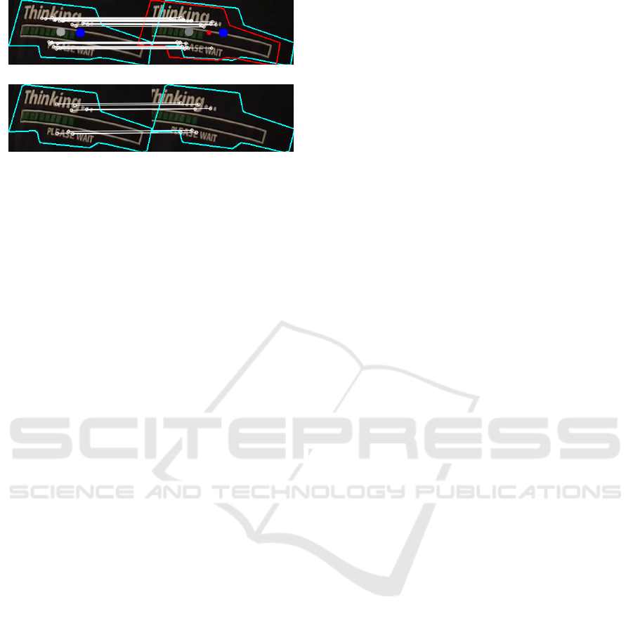
(a) ≥ 10 key points – automatic adjustment of the AOI
(b) < 10 key points – actively request for interaction
Figure 4: Example of used ORB key points for the AOI
fitting. On the left: AOI of current frame; On the right: AOI
of next frame; White circles: ORB key points f
1
, f
2
,..., f
z
;
White lines: FLANN matches of key points; Blue points:
Center of gravity of key points C
F
; Gray points: Center of
gravity of the AOI C
AOI
; Red point: New center of gravity
of the AOI C
0
AOI
.
3.7 User Interface
The UI of iSeg consists of four main areas:
h
a
main
context menu,
h
b
tool bar,
h
c
frame view and naviga-
tion area, and
h
d
semantic time line as seen in Fig-
ure 5. The main context menu includes, as usually,
all options which are provided by iSeg, including in-
formation about the current version. Frequently used
tools and functions like open project, semi-automatic
AOI fitting, and tailor AOI are also available in the
tool bar. The manual AOI annotation as well as the
interactive AOI adjustment is done within the frame
view and navigation area. For adding semantic infor-
mation to the annotation, the semantic time line pro-
vides a bundle of features. To start with the obvious
all AOI are listed and color coded in the semantic time
line. Next to the AOI names different types of lines
describe the state of the AOI at this time. Possible
states are: i) the AOI is on the current frame and visi-
ble – bold line, ii) the AOI is on the current frame and
occluded or partially occluded – broken line, iii) the
AOI is not on the current frame – light line. In ad-
dition, the lines also represent the stack order of the
AOI aka z-order. Is an AOI in front of an other AOI,
the corresponding line is above the other line. In addi-
tion, dots on the lines visualize if an AOI annotation is
created manually – big dot, or created automatically
– small dot.
3.8 Multithreading
Putting the user in the loop is the central compo-
nent of iSeg. As mentioned by Shneiderman (1984),
the response time is a significant value in human-
machine interaction, also, the repose time should be
minimized. To accomplish a minimum repose time of
iSeg, the multi-core architecture of today’s computer
systems is used. Therefore, all cost intensive pro-
cess steps—load image sequence, interactive semi-
automatic AOI fitting, automatic AOI fitting and tai-
loring AOI—are implemented for multithreading.
Assigning a thread for each frame proved to be
inefficient, since creating a thread consumes more re-
sources than we save by this method. To avoid this,
iSeg detects the number of CPU cores available on the
host system. Lists of tasks for each available core are
created, which have approximately the same amount
of work and can be executed separately. With these
lists, a thread on each available core is started. In
combination with other optimization features, like the
computation of feature points only in a certain area, as
described in section 3.2, iSeg provides a minimum re-
sponse time for user interaction even in computational
expensive processes. In order to avoid restrictions on
special hardware or drivers, iSeg does not use specific
GPU based multithreading techniques.
4 EXPERIMENTAL TESTS
While developing, the performance of iSeg was only
evaluated on the car data set 01-car pursuit (Kurzhals
et al., 2014a). To test the reliability of iSeg’s process,
we used three additional data sets. A representative
sample frame of all data sets can be seen in Figure 1.
As a test for highly dynamic boundaries, we chose
the 03-dialog (Kurzhals et al., 2014a), because face
boundaries exhibit the desired rapid change. Further,
we used frames 0 − 60 of the S1 L1 PET2009 video
by Ferryman and Shahrokni (2009) and the roaddata
set by Wu et al. (2014). We chose the last two videos
to be able to compare our iSeg with SAGTA.
In the test series, the same objects were annotated
with the use of iSeg as the existing annotation. To give
an idea how long the annotation process using iSeg
needs, the processing time is determined. The results,
the number of annotated objects, and the processing
time are summarized in Figure 6.
5 DISCUSSION AND
CONCLUSION
As shown in Figure 6, the tool iSeg for polygon-
shaped object annotation and segmentation works
well on different scenarios. Comparing the process-
ing time (annotation time) of iSeg on the road data
set with the processing time of SAGTA (Wu et al.,
2014), our approach takes 33min longer for creat-
Pixel-wise Ground Truth Annotation in Videos - An Semi-automatic Approach for Pixel-wise and Semantic Object Annotation
695
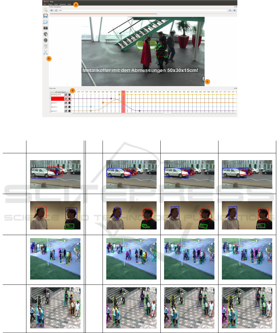
Figure 5: User interface of iSeg with its four main areas:
g
a
main context menu;
g
b
tool bar;
c
frame view and navigation
area;
g
d
semantic time line.
Original
rectangular AOI
Resulting
polygon AOI
Resulting minimal
rectangular AOI
Resulting
rectangular AOI
01-car pur-
suit (Kurzhals
et al., 2014a)
#objects: 2
time: 22min
03-dialog
(Kurzhals
et al., 2014a)
#objects: 3
time: 41min
S1 L1 PET2009
(Ferryman and
Shahrokni, 2009)
#objects: 11
time: 59min
road
(Wu et al., 2014)
#objects: 10
time: 24min
Figure 6: Resulting AOI using iSeg.
ing the annotations. But since polygon-shaped AOI
contain much more information and are more accu-
rate than rectangular AOI, this result is not surprising.
A comparative evaluation based on polygon-shaped
AOI was not possible for us. As stated above, VIA is
the only video annotation tool, which should support
polygon-shaped AOI (Dasiopoulou et al., 2011), but
we did not find the option for it.
Polygonal annotation is clearly worth the trouble:
Compared to rectangles, it allows for a much more
precise description of the boundaries. A precise de-
scription of boundaries improves the 3D object recon-
ICPRAM 2016 - International Conference on Pattern Recognition Applications and Methods
696

struction from video footage (Sch
¨
oning, 2015) and
for video inpainting. For other applications like the
analysis of gaze data (Kurzhals et al., 2014b), which
mostly depends on a rectangular description of the
AOI, this rectangular description can easily be derived
from the polygon description.
To overcome the still existing restrictions of our
implementation, we will extend the activity diagram
(Fig. 3) with components which detect deformation
and rotation. Thus the affine transformation of the
AOI can be improved significantly.
The current prototype of iSeg is GPLv3 licensed
and available online
2
.
ACKNOWLEDGEMENTS
This work was funded by the German Research Foun-
dation (DFG) as part of the Scalable Visual Analytics
Priority Program (SPP 1335).
REFERENCES
Alt, H. and Guibas, L. J. (1996). Discrete geometric shapes:
Matching, interpolation, and approximation: A sur-
vey. Technical report, Handbook of Computational
Geometry.
Boykov, Y., Veksler, O., and Zabih, R. (2001). Fast approxi-
mate energy minimization via graph cuts. IEEE Trans.
Pattern Anal. Mach. Intell., 23(11):1222–1239.
Caselles, V., Kimmel, R., and Sapiro, G. (1997). Geodesic
active contours. Int J Comput Vision, 22(1):61–79.
Cobos, F. and Peetre, J. (1991). Interpolation of compact
operators: the multidimensional case. Proc. Lond.
Math. Soc., 3(2):371–400.
Dasiopoulou, S., Giannakidou, E., Litos, G., Malasioti, P.,
and Kompatsiaris, Y. (2011). A survey of semantic
image and video annotation tools. Lect Notes Comput
Sc, pages 196–239.
Doermann, D. and Mihalcik, D. (2000). Tools and tech-
niques for video performance evaluation. Interna-
tional Conference on Pattern Recognition, 4:167 –
170.
Ferryman, J. and Shahrokni, A. (2009). PETs2009: Dataset
and challenge. IEEE International Workshop on Per-
formance Evaluation of Tracking and Surveillance.
Gotsman, C. and Surazhsky, V. (2001). Guaranteed
intersection-free polygon morphing. Comput Graph,
25(1):67–75.
H
¨
oferlin, B., H
¨
oferlin, M., Heidemann, G., and Weiskopf,
D. (2015). Scalable video visual analytics. Inf Vis,
14(1):10–26.
2
Source code and binaries for Ubuntu, Mac OS X and
Windows: https://ikw.uos.de/∼cv/projects/iSeg
Kurzhals, K., Bopp, C. F., B
¨
assler, J., Ebinger, F., and
Weiskopf, D. (2014a). Benchmark data for evaluating
visualization and analysis techniques for eye tracking
for video stimuli. Workshop on Beyond Time and Er-
rors Novel Evaluation Methods for Visualization.
Kurzhals, K., Heimerl, F., and Weiskopf, D. (2014b).
Iseecube: visual analysis of gaze data for video. Sym-
posium on Eye Tracking Research and Applications,
pages 43–50.
Lowe, D. G. (2004). Distinctive image features from scale-
invariant keypoints. Int J Comput Vision, 60(2):91–
110.
Muja, M. and Lowe, D. G. (2009). Fast approximate near-
est neighbors with automatic algorithm configuration.
International Conference on Computer Vision Theory
and Applications, 2:331–340.
Multimedia Knowledge and Social Media Analytics Lab-
oratory (2015). Video image annotation tool.
http://mklab.iti.gr/project/via.
Rother, C., Kolmogorov, V., and Blake, A. (2004). “Grab-
Cut” interactive foreground extraction using iterated
graph cuts. ACM Trans Graph, 23(3):309–314.
Rublee, E., Rabaud, V., Konolige, K., and Bradski, G.
(2011). ORB: an efficient alternative to SIFT or
SURF. IEEE International Conference on Computer
Vision, pages 2564–2571.
Sch
¨
oning, J. (2015). Interactive 3D reconstruction: New op-
portunities for getting cad-ready models. In Imperial
College Computing Student Workshop, volume 49,
pages 54–61. Schloss Dagstuhl–Leibniz-Zentrum fuer
Informatik.
Sch
¨
oning, J., Faion, P., and Heidemann, G. (2015). Semi-
automatic ground truth annotation in videos: An in-
teractive tool for polygon-based object annotation and
segmentation. In International Conference on Knowl-
edge Capture, pages 17:1–17:4. ACM, New York.
Schroeter, R., Hunter, J., and Kosovic, D. (2003). Vannotea
- A collaborative video indexing, annotation and dis-
cussion system for broadband networks. Workshop on
Knowledge Markup & Semantic Annotation,pages 1–8
Shneiderman, B. (1984). Response time and display rate
in human performance with computers. ACM Comput
Surv, 16(3):265–285.
Tanisaro, P., Sch
¨
oning, J., Kurzhals, K., Heidemann, G.,
and Weiskopf, D. (2015). Visual analytics for video
applications. it-Information Technology, 57:30–36.
Wu, S., Zheng, S., Yang, H., Fan, Y., Liang, L., and Su, H.
(2014). Sagta: Semi-automatic ground truth annota-
tion in crowd scenes. IEEE International Conference
on Multimedia and Expo Workshosps.
Yao, A., Gall, J., Leistner, C., and Van Gool, L. (2012).
Interactive object detection. International Conference
on Pattern Recognition, pages 3242–3249.
YouTube (2015). Statistics - youtube: https://www.
youtube.com/yt/press/statistics.html.
Pixel-wise Ground Truth Annotation in Videos - An Semi-automatic Approach for Pixel-wise and Semantic Object Annotation
697
