
A Ground Truth Vision System for Robotic Soccer
Ant
´
onio J. R. Neves, Fred Gomes, Paulo Dias and Alina Trifan
Universidade de Aveiro, IEETA/DETI - IRIS Laboratory, Aveiro, Portugal
Keywords:
Ground Truth, Robotic Vision, Robotic Soccer, Monitoring System.
Abstract:
Robotic soccer represents an innovative and appealing test bed for the most recent advances in multi-agent
systems, artificial intelligence, perception and navigation and biped walking. The main sensorial element of
a soccer robot must be its perception system, most of the times based on a digital camera, through which the
robot analyses the surrounding world and performs accordingly. Up to this date, the validation of the vision
system of a soccer robots can only be related to the way the robot and its team mates interpret the surroundings,
relative to their owns. In this paper we propose an external monitoring vision system that can act as a ground
truth system for the validations of the objects of interest of a robotic soccer game, mainly robots and ball. The
system we present is made of two to four digital cameras, strategically positioned above the soccer field. We
present preliminary results regarding the accuracy of the detection of a soccer ball, which proves that such a
system can indeed be used as a provider for ground truth ball positions on the field during a robotic soccer
game.
1 INTRODUCTION
This paper presents preliminary results on the use of a
vision system designed for the monitoring and track-
ing of a robotic soccer game. The external vision sys-
tem was designed with the purpose of being used as
a ground truth validation system for the positions of
the soccer ball and robots in real-world coordinates.
The system we propose consists of two to four digi-
tal cameras strategically positioned above the soccer
field. In this way 3D information about the soccer
ball can be reconstructed from the images of the same
scene acquired by all cameras. This paper intends to
be a contribution for the area of computer vision, with
application in robotic soccer, since up to date robotic
vision systems used in soccer games do not use any
kind of ground truth validations.
3D information recovery is of high importance
in robotics applications, such as bin picking, object
tracking or product profiling, just to name a few. 3D
information can be obtained using passive or active
methods. Passive methods, such as stereo vision, re-
quire that the environment is sufficiently illuminated.
On the other hand, active methods such as structure
laser light and pattern-based lighting systems use ex-
ternal light sources in order to obtain the 3D recon-
struction of the environment (Design, 2014).
The system we are proposing is essential for the
validation of object detection methods developed in
this field. Until today, most of the information re-
lated to the detection of the objects of interest in a
robotic soccer game was only obtained directly from
the vision systems of the robots. The system that we
propose is a passive one and integrates multiple digi-
tal cameras, installed in fixed positions on the soccer
field.
The paper is structured in 6 sections, first of them
being this Introduction. We present an overview of
the work done in 3D information recovery and 3D
tracking in Section 2. Section 3 presents the details
of the camera calibration approach. The algorithm
used for ball detection is presented in Section 4. Pre-
liminary results are presented in Section 5. Finally,
Section 6 concludes the paper, followed by the ac-
knowledgement of the institutions that supported this
work.
2 RELATED WORK
Industrial systems such as Simi Motion
1
or Ki-
novea
2
are designed for tracking a person based on
their silhouette. Unlike other systems, these ones do
not use infra-red technology. The silhouette is de-
tected based on the articulations of the human body.
1
http://www.simi.com/en/
2
http://www.kinovea.org/
684
Neves, A., Gomes, F., Dias, P. and Trifan, A.
A Ground Truth Vision System for Robotic Soccer.
DOI: 10.5220/0005817506840689
In Proceedings of the 5th International Conference on Pattern Recognition Applications and Methods (ICPRAM 2016), pages 684-689
ISBN: 978-989-758-173-1
Copyright
c
2016 by SCITEPRESS – Science and Technology Publications, Lda. All rights reserved
In order to facilitate this process, additional markers
can be placed on the human body for a higher pre-
cision. This kind of approaches are not suitable for
robotic soccer since the rules do not allow the use of
external markers.
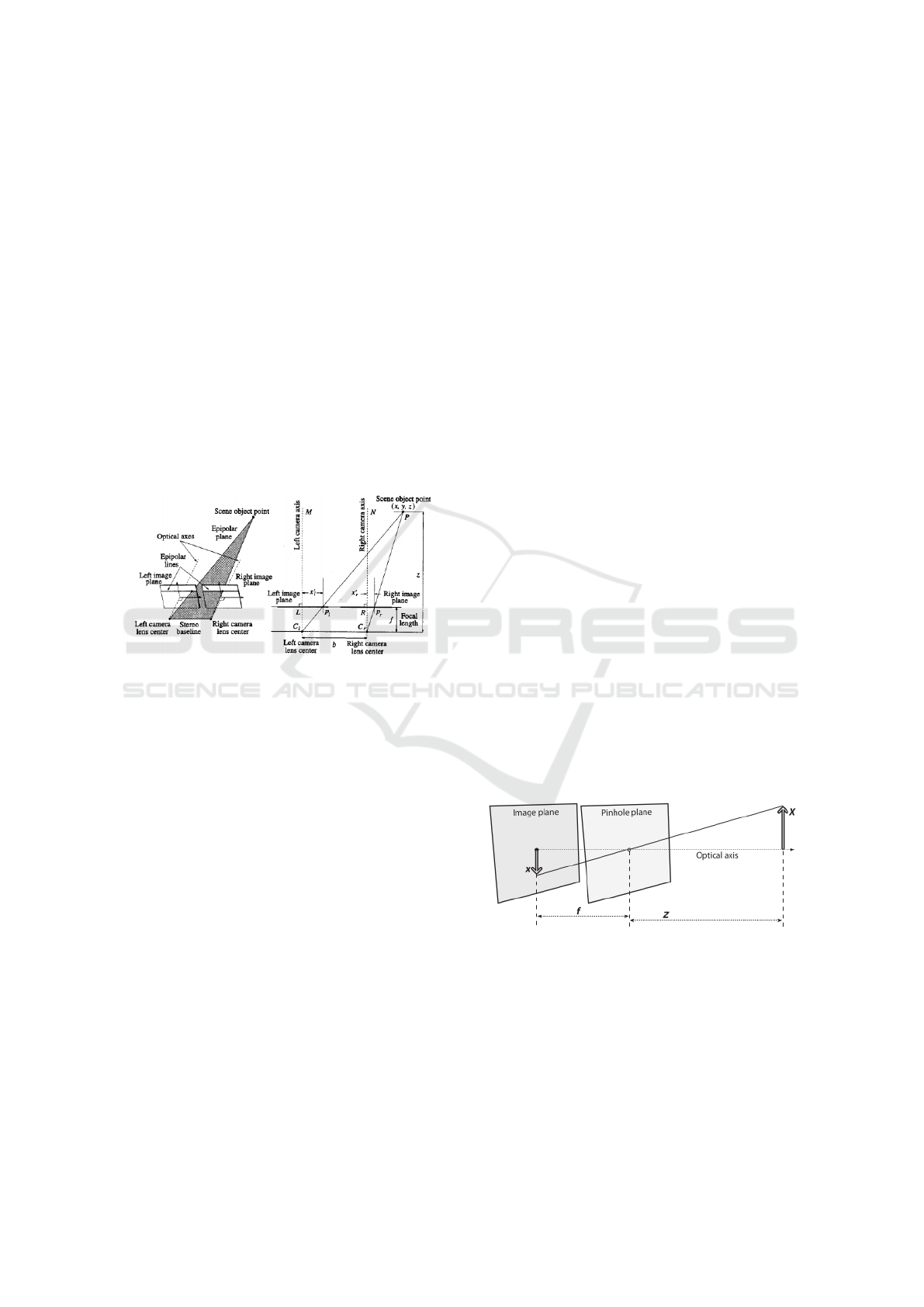
Stereo vision was inspired by the human vision.
The human eyes are located at 60mm from one an-
other and each eye perceives the surrounding world
in a different manner. The difference in the projec-
tions of the same point viewed by both eyes in the
two retinas is defined as binocular disparity. The no-
tion of disparity contributes to the understanding of
the notion of depth (Qian, 1997). Our brain uses the
horizontal disparity in order to estimate the depth in-
formation. Stereo vision is based on this principle and
allows the reconstruction of a 3D scene based on the
use of two digital cameras (Ramesh Jain Rangachar
Kasturi, 1995) (Fig. 1).
Figure 1: Illustration of the stereo vision principle of func-
tioning.
A system for tracking sports players based on mul-
tiple cameras is presented in (Puwein et al., 2011).
This method consists not only in the calibration of
each frame from the cameras, but also in taking
advantage of the multiple correspondences among
frames. New cameras can be added to this system
at any time, in order to improve its robustness. One
of the challenges of this method is to establish cor-
respondences among multiple cameras. This is done
by finding invariant descriptors for each feature of
the objects in the images. The locations of these
features use a common coordinate system among all
cameras. A comparison between the descriptors of a
given frame and the ones of the previous frame is es-
tablished and a bag of features is updated.
In (Yamada A, 2002) another approach for track-
ing soccer players and ball is presented. This method
is used in TV broadcasting and is based on the rota-
tion and zoom of a camera. Camera calibration is per-
formed based on the extraction of interest points on
the field, such as lines and circles. This calibration re-
sults in a straightforward relation between pixels and
world coordinates.
A first attempt to building a ground truth vali-
dation system for robotic soccer has been presented
in (Silva et al., 2012) and was later reused in (Ah-
mad et al., 2014). The ground truth system consists
of two cameras with a baseline of 12m. These works
lack an explanation regarding the chosen positioning
of the cameras on the soccer field. In the work that we
propose, we extend this idea by using up to four cam-
eras and we justify their positions on the field, such
as to obtain a high coverage percentage at any point
in time.
3 CAMERA CALIBRATION
The firs requirement of the ground truth system that
we propose is to provide a correspondence between
the referential of a camera and the real world, in this
case, the soccer field. With this in mind, we have im-
plemented a graphical tool which allows the calibra-
tion of the intrinsic and extrinsic parameters of a cam-
era, in a supervised manner. The intrinsic parameters
of a camera describe the geometrical properties of that
camera, while the extrinsic ones relate the position of
a camera to a given referential (the soccer field in this
case).
3.1 Intrinsic Parameters
Intrinsic parameters define the coordinates of a given
pixel in camera coordinates. They are: focal distance,
optical center and distortion coefficient. The geome-
try of a camera is usually described based on the pin-
hole model (Fig. 2), which is used for determining the
intrinsic parameters:
Figure 2: Pinhole Camera Model.
The following equations show the relation be-
tween pixels and camera coordinates, based on intrin-
sic parameters:
x
pix
y
pix
=
α
x
γ c
x
0 α
y
c
y
·
x
s
y
s
z
s
(1)
where
α
x
= f
x
· m
x
α
y
= f
y
· m
y
(2)
A Ground Truth Vision System for Robotic Soccer
685

• f is the focal distance;
• m
x
, m
y
are scale factors that relate pixels to metric
distances.
The equations system presented in 1 cannot be
directly solved. Obtaining 2D information from 3D
data is a trivial procedure, but the opposite one is not.
To solve this system, one of the following parameters
must be known: x
s
, y
s
or z
s
. Having more than one
image of the same scene makes it possible to find the
missing parameter and thus recover the 3D informa-
tion.
3.2 Lens Distortion
Two main types of lens distortion can be observed:
radial and tangential. Radial distortion is given by
the shape of the lens, while the tangential distortion is
attributed to the mounting of the camera as a whole.
Figure 3 shows the impact of the radial and tan-
gential distortion in an image.
(a) Radial distortion. (b) Tangential distortion.
Figure 3: Distortion effect for a given camera. Each ar-
row represents the displacement of a pixel due to radial and
tangential distorsion. The cross indicates the center of the
image and the circle indicates the principal point (Bouguet,
2014).
3.3 Extrinsic Parameters
The extrinsic parameters define the localization and
orientation of the camera in relation to the world co-
ordinates system. The relation between a world point,
P
W
and the same point P
C
, in camera coordinates, is
given by:
P
C
= R · (P
W
− T ) (3)
where R e T are the rotation and translation matri-
ces in the global referential.
We have developed an user supervised graphical
tool for the calibration of the camera parameters. This
tool has been built using the OpenCV Library .
3
One
of the most used camera calibration algorithm has
been proposed in (Zhang, 2000). This algorithm is
based on the use of a well-known object with a regu-
lar pattern, most of the time a chessboard. Using an
3
www.opencv.org
edge detection algorithm, the edges of the chessboard
can be detected and the camera parameters are ex-
tracted based on the location of the edges. The intrin-
sic parameters are estimated in an iterative manner, by
using multiple visualizations of the chessboard. Fig-
ure 4 exemplifies this process:
Figure 4: Chessboard images of different orienta-
tions (Kaehler and Gary, 2013) used for the calibration pro-
cess.
The following equation presents the mathematical
expression of the positioning of the camera relative to
a global referential.
C = −R
|
· T (4)
The application works as follows: the user pro-
vides several views of the chessboard, at different ori-
entations. The corners of each square is calculated
and the intrinsic parameters of the camera are esti-
mated based on this relation.
For the calculation of the extrinsic parameters, the
user has to click on a point in an image and manu-
ally introduce its coordinates in real-world referential.
The positioning of the camera relative to a global ref-
erential can be estimated by the correspondence of a
pixel in a 2D image and the 3D coordinates of the
same point. In order to facilitate the calibration pro-
cedure, every time the user clicks on a pixel in the im-
age, he has the possibility of zooming-in, thus defin-
ing the pixel position with a higher precision. The
correspondence between pixels and world coordinates
is done manually, by clicking on a chosen pixel and
inserting the 3D real coordinates, within the soccer
field, of the same pixel.
4 3D BALL DETECTION
We have developed a graphical tool for visualizing the
position of the cameras on the soccer field. Moreover,
this tool supports the visualization of the projection
of the ball direction vectors, for different cameras, as
well as the ball position on the field (Fig. 6). We have
conducted initial experiments using two digital cam-
eras.
The ball detection algorithm follows the approach
presented in (Neves et al., 2014), in which blobs of
the color of the ball are detected. The ball is validated
ICPRAM 2016 - International Conference on Pattern Recognition Applications and Methods
686
based on a series of measurements such as as: round-
ness, size and width/height relation. In order to find
the 3D position of the ball, we detect the ball in an im-
age acquired by the first camera and we calculate its
center. This procedure is repeated for the frame ac-
quired by the second camera. For each ball center, a
vector is projected from the optical center towards the
center of the ball. In a triangulation of two vectors,
due to errors in the ball position, these vectors might
not intersect. To overcome this, instead of calculating
the intersection between two vectors, we calculate the
closest point between them.
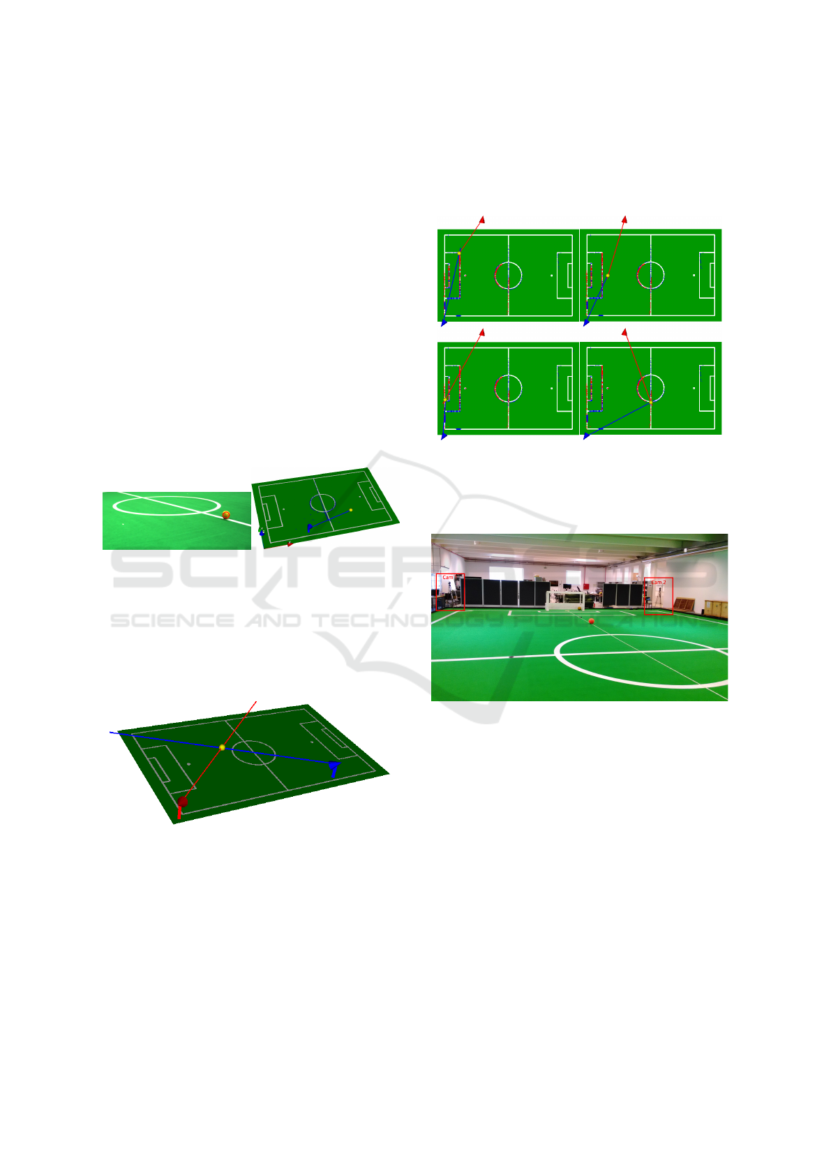
Figure 5 a) shows the detection of the ball in an
image and Figure 5 b) shows the projection of a 3D
vector towards the pixel corresponding to the center of
the ball. The intersection of the vector with the plan of
the field does not correspond to the real coordinates of
the ball and this is due to the height of the ball, which
is higher than the plan of the floor. To compensate
this, more cameras should be used.
(a) (b)
Figure 5: a) Ball detection using the library UAVision. e b)
Projection of a vector, from the optical center towards the
center of the ball.
Figure 6 shows the projection of two vectors for
the two different cameras used in this first test. The
closest point between them defines the 3D coordinates
of the ball.
Figure 6: Projection of the two vectors towards the center
of the ball; the intersection of these vectors defines the 3D
center of the ball.
5 EXPERIMENTAL RESULTS
In these preliminary tests, the accuracy of the system
is tested by placing the ball in known positions on the
soccer field and comparing these positions to the ones
returned by our software.
The two cameras were placed in two corners of
the soccer field. Several images were capture with the
ball placed in known positions on the field (Fig. 7).
The ball is gradually moved away from the cameras.
Figure 7: Triangulation method for obtaining the 3D coor-
dinates of the soccer ball.
Figure 8 shows the setup that was used for these
results.
Figure 8: Illustration of the soccer field and the placement
of the two cameras.
Figure 9 shows the ball coordinates on the field
(in blue points) and the coordinates calculated by the
system we propose (in red). Table 1 shows the error,
in mm, between the two sets of coordinates.
We can verify that, as the ball is moved away from
the cameras, the error is not linear. The ball is placed
at distances starting in 2.880m in a) up to 17.875m in
p) and the errors obtained are quite low.
We have performed another test for evaluating the
global performance of the system. We have placed
two cameras on the field, with a wide baseline be-
tween them and we have repeated the previous tests.
Figure 10 shows the positions of the cameras.
Figure 11 shows the ball coordinates on the field
(in blue points) and the coordinates calculated by the
system we propose (in red) for this setup.
A Ground Truth Vision System for Robotic Soccer
687
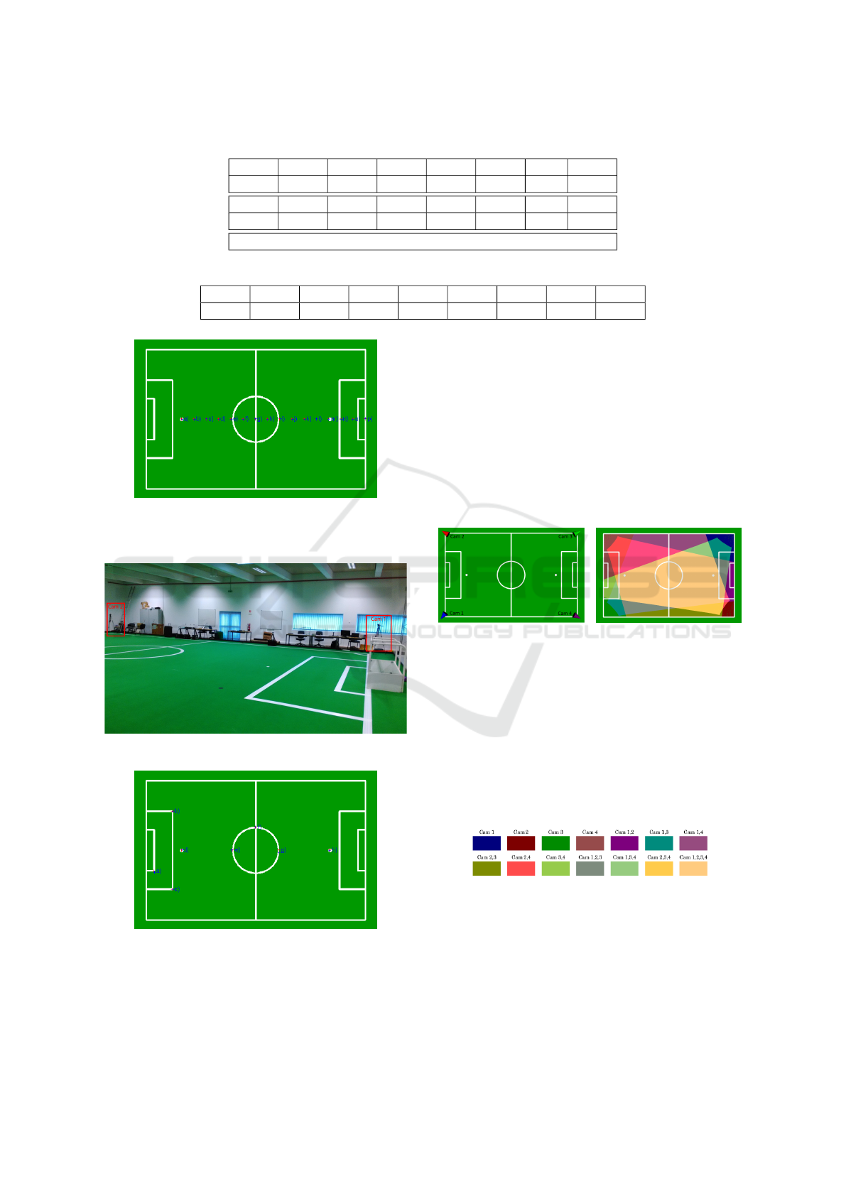
Table 1: Euclidian distance between the coordinates on the field and the ones calculated by our system, in mm.
a) b) c) d) e) f) g) h)
50.30 40.03 37.90 41.65 40.16 47.12 5.15 31.52
i) j) k) l) m) n) o) p)
48.15 69.09 56.01 21.11 14.21 22.73 9.30 7.53
Average: 33.88
Table 2: Euclidian distance, in mm, between the ball coordinates on the field and the coordinates calculated by the system.
a) b) c) d) e) f) g) h) Mdia
10.53 70.74 67.59 55.83 72.01 35.24 33.04 44.25 48.65
Figure 9: Ball coordinates on the field (in blue points) and
the coordinates calculated by the system we propose (in
red).
Figure 10: Two cameras with a wide baseline setup.
Figure 11: Ball coordinates on the field (in blue points)
and the coordinates calculated by the system we propose
(in red).
Table 2 shows the error, in mm, between the two
sets of coordinates.
In both of the previous setups, the errors were
small for all ball positions, of the orders of millime-
tres. This proves that the system could be used only
with two cameras, if needed. We complement these
results with the study of the system when using four
cameras, in an attempt to improve the errors that have
been presented so far.
Figure 12 a) shows a configuration with four cam-
eras and Fig. 12 b) shows their field of view. Fig-
ure 13 shows the color map corresponding to the field
of view of each of the cameras.
(a) (b)
Figure 12: a) Setup integrating four cameras b) Field of
view of the different cameras. For this configuration, 10%
of the field is seen by one camera, 27 % is seen by two
cameras, 21 % is seen by three cameras e 42% is seen by
the four cameras.
For this configuration of cameras, the triangu-
lation should be performed for information coming
from the four cameras, given that most of the field is
seen by three or more cameras. A very small percent-
age of the field is seen by only one or two cameras.
Figure 13: Color map corresponding to the field of view of
each of the cameras.
This configuration of the cameras is considered
to be optimal for improving the detection results ob-
tained only with two cameras. The following algo-
rithm has been used for choosing this configuration:
• A set of 3D points along the soccer field has been
chosen.
ICPRAM 2016 - International Conference on Pattern Recognition Applications and Methods
688

• We verify which of all these 3D points is seen by
the four cameras.
• For each point that is seen by two or more cam-
eras, we project the vectors from the optical center
of each camera until the respective 3D point. We
calculate the angle between all cameras and this is
saved in a data structure.
• In the end, for each 3D point we choose the angle
that is closest to 90deg.
6 CONCLUSIONS
We have presented in this paper an autonomous sys-
tem for the detection of the objects of interest in a
robotic soccer game, based on the use of multiple dig-
ital cameras. We presented preliminary results on the
triangulation of the information acquired from two
cameras, applied to the detection of the soccer ball.
These results show errors of the orders of millimeters
for the detection of the center of the ball. Moreover,
we proposed the use of this system with three or four
digital cameras, whose strategic positions on the field
have been thoroughly researched in order to guaran-
tee an optimal joint field of view. We are confident
that these configurations can lead to even better re-
sults on the object detection and this will be the future
step in the development of this system. The final and
complete system is intended as a ground truth vision
system that can be used for the validation of robotic
vision systems in soccer games.
ACKNOWLEDGEMENTS
This work was developed in the Institute of Electronic
and Telematic Engineering of University of Aveiro
and was partially supported by FEDER through
the Operational Program Competitiveness Factors -
COMPETE FCOMP-01-0124-FEDER-022682 (FCT
reference PEst-C/EEI/UI0127/2011) and by National
Funds through FCT - Foundation for Science and
Technology in a context of a PhD Grant (FCT ref-
erence SFRH/BD/85855/2012).
REFERENCES
Ahmad, A., Xavier, J., Santos Victor, J., and Lima, P.
(2014). 3d to 2d bijection for spherical objects under
equidistant fisheye projection. 125(1):172–183.
Bouguet, J.-Y. (2014). Camera Calibration Toolbox for
Matlab.
Design, V. S. (2014). Choosing a 3D vision system for auto-
mated robotics applications - Vision Systems Design.
Kaehler, A. and Gary, B. (2013). Learning OpenCV.
O’Reilly Media.
Neves, A. J. R., Trifan, A., and Cunha, B. (2014). UAVi-
sion: A modular time-constrained vision library for
color-coded object detection. Lecture Notes in Com-
puter Science (including subseries Lecture Notes in
Artificial Intelligence and Lecture Notes in Bioinfor-
matics), 8641 LNCS:351–362.
Puwein, J., Ziegler, R., Vogel, J., and Pollefeys, M.
(2011). Robust multi-view camera calibration for
wide-baseline camera networks. 2011 IEEE Workshop
on Applications of Computer Vision, WACV 2011,
pages 321–328.
Qian, N. (1997). Binocular Disparity and the Perception of
Depth.
Ramesh Jain Rangachar Kasturi, B. G. S. (1995). Machine
Vision. McGraw-Hill, Inc.
Silva, H., Dias, A., Almeida, J., Martins, A., and Silva,
E. (2012). Real-time 3d ball trajectory estimation for
robocup middle size league using a single camera. In
Rfer, T., Mayer, N., Savage, J., and Saranl, U., ed-
itors, RoboCup 2011: Robot Soccer World Cup XV,
volume 7416 of Lecture Notes in Computer Science,
pages 586–597. Springer Berlin Heidelberg.
Yamada A, S. Y. M. J. (2002). Tracking Players and a
Ball in Video Image Sequence and Estimating Cam-
era Parameters for 3D Interpretation of Soccer Games.
Pattern Recognition, 2002. Proceedings. 16th Interna-
tional Conference on (Volume:1 ), vol.1(1):303–306.
Zhang, Z. (2000). A flexible new technique for camera cal-
ibration. IEEE Transactions on Pattern Analysis and
Machine Intelligence, 22(11):1330–1334.
A Ground Truth Vision System for Robotic Soccer
689
