
Instructor Contour Extraction and Overlay for Near-real Presence in
e-Learning Systems
Ramkumar N, Balaji Hariharan, Uma Gopalakrishnan and Venkat Rangan
Amrita Wireless Networks and Applications, Amrita School of Engineering,
Amrita Vishwa Vidyapeetham University, Amritapuri Campus, Vallikavu, Kollam, India
Keywords: Enhancing Immersion, People Extraction, Visual Correlation, Contour Overlay, Virtual Presence.
Abstract: E-Learning technologies focus on methods to replicate entities such as white board, presentation screen and
other teaching aids in remote classrooms. Often, a high detail video stream of the whiteboard or presentation
screen (board-stream) is streamed to the remote classroom along with the instructor’s video stream.
However, remote participants find it difficult to correlate between the two displayed streams to find out the
area focused by the instructor‘s gestures such as finger pointing over the board. This paper deals with a
method to overlay the instructor's contour-extracted frames from the instructor-stream over the board-stream
for remote participants. Since the board-stream and instructor-stream have different camera perspectives, a
transformation from the instructor’s video perspective to the board-stream perspective has to be made
before overlay. The process includes finding the Homography-matrix, warping and overlay. Our
performance results indicate that remote participants are able to discern the area focused by the instructor on
the board with much greater accuracy and speed.
1 INTRODUCTION
Gesture-based cues tend to convey a lot of
information and are vital for effective communication
especially in a dynamic environment like a classroom.
When this environment is adapted to an e-Learning
scenario, a lot of the vicarious information such as
gestures, facial expression is lost and due to this, the
remote students are often disadvantaged as compared
to students present in the teachers location. In this
paper, we have developed a system that enhances the
instructor’s presence in the remote classroom,
providing a more immersive experience.
1.1 Problem Description
In a remote classroom, the video of the instructor is
often shown while the details of the whiteboard or
presentation screen in the video are obscure due to
lossy compression during encoding, and packet
losses during transmission. To resolve this, most E-
Learning solutions today such as Adobe Captivate
(Huettner, Brenda., 2008), AView (Bijlani, Kamal,
et al. 2010) etc. display a high definition video of the
board in the remote classroom for students to see.
The board-stream is a high resolution, low frame
rate video of the board captured through screen-cast
methods or a good quality video-capture device. The
instructor however is not captured in this stream. In
this scenario, the instructor’s gestures on the board
are rendered meaningless for the remote students.
They have to discern the area of focus on the board
from audio sources or other contextual means.
To circumvent this problem, both streams i.e.
instructor’s video (instructor-stream) and the board-
stream are often transmitted to the remote locations.
The video streams are then decoded and displayed on
two display areas. However, the remote students now
have to discern the area of focus by looking at the
instructor-stream and then finding the corresponding
location which the instructor is pointing at on the
board-stream. Over time, this adds to a lot of strain for
the remote students, impeding the learning process.
1.2 Our Contribution
To solve this problem, we propose a method to
extract the instructor’s contour from the instructor-
stream by removing the background data and
retaining only the instructor’s body profile from the
video stream, and then overlaying it on the board-
stream. Since the instructor-stream and the board-
stream have different camera perspectives, direct
N, R., Hariharan, B., Gopalakrishnan, U. and Rangan, V.
Instructor Contour Extraction and Overlay for Near-real Presence in e-Learning Systems.
In Proceedings of the 8th International Conference on Computer Supported Education (CSEDU 2016) - Volume 1, pages 353-358
ISBN: 978-989-758-179-3
Copyright
c
2016 by SCITEPRESS – Science and Technology Publications, Lda. All rights reserved
353

overlay of the instructor’s contour-extracted images
on the board-stream would result in no correlation
between the actual area of focus on the board and the
area that the instructor is pointing to in the overlayed
video stream. Direct overlay would result in
misalignment of the physical positioning of the
instructor’s contour over the board; the overlayed-
stream in the remote classrooms would not reflect the
actual area on the board that the instructor is pointing
to in the classroom that he/she is physically present.
The following steps are involved in the
instructor-contour extraction and overlay process.
1) Instructor-contour Extraction
To extract the instructor-contour, we employ
Microsoft’s Kinect Sensor with OpenNI2 and NITE
(Davison., Andrew., 2012) API frameworks. The
output of this step is a sequence of frames with only
the instructor’s body profile, henceforth referred to as
Instructor-Contour-Extracted frames or ICE-frames.
These frames are of Kinect camera’s perspective.
2) Calibration of the Transformation Matrix
Since the ICE-frames and board-frames (individual
frames from the board-stream) have different
perspective, the ICE frames cannot be overlayed on
the board frames without transformation. This
process of translating an image from one perspective
to another is called Image-Registration, and is
achieved through a transformation matrix called the
Homography- Matrix. Details of obtaining the
Homography-Matrix are discussed in section 3.1.
3) Image-registration of the Instructor-contour-
extracted Frames
Reshaping of an image to align perspectives with
another image is done by the process of warping.
The ICE-frames are warped using the Homography-
Matrix and the obtained frames correspond to the
perspective of the board-frames (
Wolberg, George.,
1990
). Thus they are henceforth called Instructor-
Contour-Extracted-Warped frames or ICEW-frames.
4) Encoding and Transmission of Board-frames
and ICEW-frames
Board-frames are high resolution frames (
Lavrov,
Valeri. 2004
) and they are encoded and transmitted as
board-stream over the network to the remote
location at 3 frames per second. The ICEW-frames
contain the instructor’s contour and are highly
dynamic. They are thus encoded and transmitted at
30 frames per second. The ICEW-frames are
encoded with instructor’s audio and transmitted as
ICEW-stream.
5) Decoding and Overlay
The ICEW-stream and the board-stream are decoded
at the receiving end to obtain frames. The frames are
buffered appropriately to match for time stamps of
network packets before the overlay process. Ten
ICEW-frames are overlayed on one board-frame and
these are henceforth called overlayed-frames. The
overlayed-frames are played-back at 30 frames per
second at each of the remote participants locations.
To evaluate the system, 20 participants were
subjected to an experiment. The experiment
involved an array of numbers on the board with the
instructor pointing at random numbers on the board.
The remote students had to identify the numbers in
the shortest time possible. The experiment was
conducted over two sessions; 1) with two screens -
one displaying the instructor-stream and the other
displaying the board-stream and 2) with one screen –
displaying the instructor’s contour extracted frames.
Results were calculated based on both accuracy and
average time required for identification. Objective
and subjective results are presented in section 4.
2 RELATED WORK
People detection is the first step involved in the
extraction of people’s body contour. From the depth
map of the scene provided by the Kinect’s infrared
sensor, the 3D contour of a body is extracted. Work
done by Krishnamurthy, Sundar Narayan delves into
the intricacies of contour extraction (Krishnamurthy,
Sundar Narayan, 2011).
Work done by Lowe, David G on scale invariant
feature transforms describes methods to find the
matching features for image correspondences. This is
one of the seminal works in computer vision wherein
he describes the computation of high frequency
keypoints and their associated descriptor vectors for
each of the images. The paper also covers feature
matching between keypoints after comparing the
descriptors. Strong matches are found and the
algorithm calculates the best matching keypoint pairs
between the images (Lowe, David G., 2004).
Ramponi, G describes methods for interpolation of
image pixels facilitating warping for better perceptual
rendition of images. His technique involves a linear
approach to bilinear interpolation thus saving largely
on computation costs (Ramponi, Giovanni., 1999).
3 PROPOSED SOLUTION
The proposed solution involves enhancing the
presence of the instructor in the remote classroom.
CSEDU 2016 - 8th International Conference on Computer Supported Education
354
The disparity in connectedness between the two
screens in solutions hitherto is removed by
extracting the instructors contour and displaying it
on a high detail board stream. The process flow is
divided into two parts viz. 1) Calibration and 2)
Warping and Overlay. The first part is described in
section 3.1 and the flow diagram is show in figure 2.
Warping and Overlay is described in section 3.2.
3.1 Calibration of Homography-matrix
The first step is to perform image registration
(transforming from kinect camera’s coordinate
system to board-frame’s camera system). This is
done in two steps
3.1.1 Extracting Matching Keypoints
To do this we use an algorithm called the Scale
Invariant Feature Transform (
Lowe, David G., 2004
).
At the start of the experiment we project high detail
image on the board. We then extract a sample board-
frame and a frame from kinect camera (instructor’s-
frame) to be analyzed using the SIFT algorithm.
SIFT extracts a list of high frequency points from
the image called the keypoints from both the frames.
A keypoint is a point or a pixel on an image that has
a radical change in pixel colour or light intensity as
compared to the neighbouring pixels. Thus they are
easily detectable by the compute. From the list of
keypoints obtained for each image, SIFT then
computes the descriptor vector for each of the
keypoints; a descriptor vector is a list of 128
numbers that describes the pixels around the
keypoint pixel. Descriptor describes the variation of
colour intensities, gradient, orientation of the gradient
etc. Thus each keypoint is associated with a 128-
length descriptor vector. We find the list of
descriptors for each of the keypoints for each frame
and then we find the correlation between the list of
descriptors of instructor’s-frame to the list of
descriptors of the board-frame to find out the keypoint
correspondences between both the frames. Here we
use FLANN based feature matching algorithm to
obtain strong matches between the descriptors. Weak
matches are rejected. Matches between descriptors are
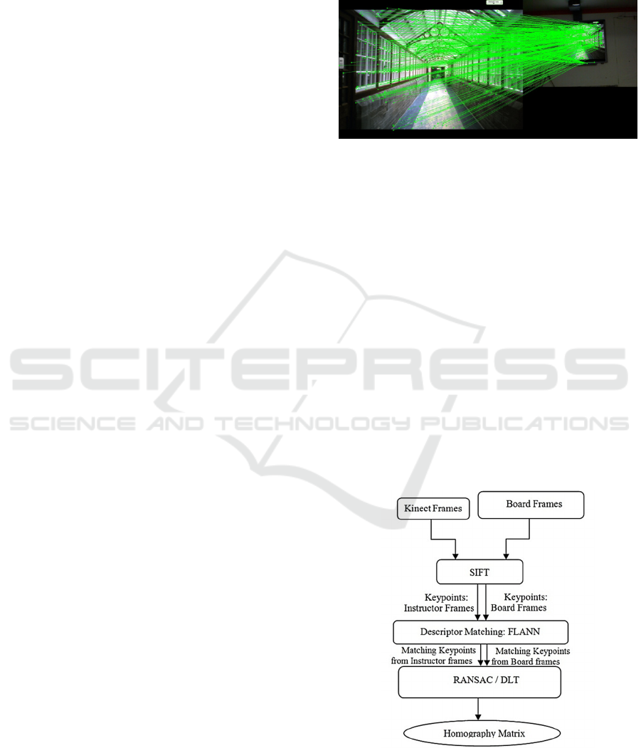
tabulated. Figure 1 shows a high resolution board-
frame and a kinect frame appended side by side into a
single image. Lines are drawn connecting the
matching keypoints between the two frames. The
green dots represent keypoints. The matching
keypoints indicate locations on board-frame that
correspond to the same location on the kinect frame.
Upon trial we found that SIFT often fails when the
matching images that do not contain sufficient detail
in terms of changes in frequency and colour
intensities. Hence for this step we project images with
large amount of details and contrasting colours.
Figure 1: Keypoints matched in appended image (Kinect
frame and board frame).
3.1.2 Calculation of Homography-matrix
from Matching Keypoints
Once the list of matching keypoints viz. the board
frame keypoints and kinect frame keypoints are
extracted, we calculate the homography-matrix.
Direct-Linear-Transformation [DLT] computes the
points
,
……
(equation 1) given the board
frame keypoints and kinect frame keypoints by
resolving them into a set of linear equations and
finding the best fit solution for the linear equations
system. Here we use the RANSAC algorithm which
computes the same faster.
∗
(1)
Figure 2: Flow diagram for Feature extraction and
computation of homography matrix.
Instructor Contour Extraction and Overlay for Near-real Presence in e-Learning Systems
355
3.2 Warping and Overlay
This section describes the various steps involved in
instructor contour extraction, warping and overlay.
In addition encoding, streaming and decoding is also
discussed. The flow diagram for the same is
described in figure 6. These steps are performed
iteratively from the start to the end of the teaching
session.
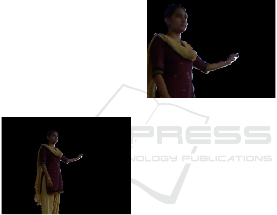
3.2.1 Instructor Contour Extraction
To obtain the ICE-frames from the kinect frames we
use the libraries OpenNi2 and NiTe. OpenNi2 is a
framework for extracting the depth and colour
streams from kinect sensor. NiTe packages the user
tracking and user contour extraction framework.
Using NiTe we extract the mask image containing
the instructor’s contour and that is then compared
with the kinect's colour stream. The colour image
contains only the instructor and the background is
subtracted. The output of this step is a sequence of
Instructor-Contour-Extracted frames (ICE frames) as
shown below in figure 3.
Figure 3: ICE frame after extraction.
3.2.2 Warping of the
Instructors-contour-extracted Frames
The determined homography-matrix is then used to
perform warping on the image for registration. This
ensures that the ICE-frames have the same
perspective as the board-frames. The kinect frames
are converted to the board-frames by multiplying
with the homography-matrix. This results in holes or
aberrations in the image. A simple Bilinear
Interpolation is performed to fill up the holes as
described by equation 2. Bilinear interpolation finds
the average of the neighbouring pixel and assigns
the average value to be filled in the hole. Thus in
effect the output of the transform is a smoothened
image. The output of this step is Instructor-Contour-
Extracted-Warped frames of ICEW-frames as shown
in figure 4 below.
,
≈
1−
0,0
0,1
1,0
1,1
1−
(2)
Figure 4: ICEW frame after extraction and warping of
instructor contour.
3.2.3 Encoding and Transmission of Board
Frames and ICEW Frames
The board-frames and ICEW-frames are then
encoded for compression and transmitted over the
network to remote locations. Since the board-frame
is relatively static and high detailed, MJPEG
compression is used. The encoding is done at 3
frames per second. The ICEW-frames and the audio
data from the instructor’s microphone are encoded
and multiplexed at 30 frames per second using the
H264 encoder.
3.2.4 Decoding and Overlay
At the receiving ends (each of the remote locations),
the board-stream and ICEW-stream are decoded to
obtain the frames and audio data. The packet delays
are accounted for by sufficient buffering. The
ICEW-frames are overlayed on the board frames at a
ratio of 10:1 and played back at the rate of 30 frames
per second. The audio data is synchronously played
back according to the time stamping. Below image
shows an overlayed-frame.
Figure 6 shows the flow diagram of the
execution of each step. These steps are performed
iteratively from the start to the end of the teaching
session.
CSEDU 2016 - 8th International Conference on Computer Supported Education
356
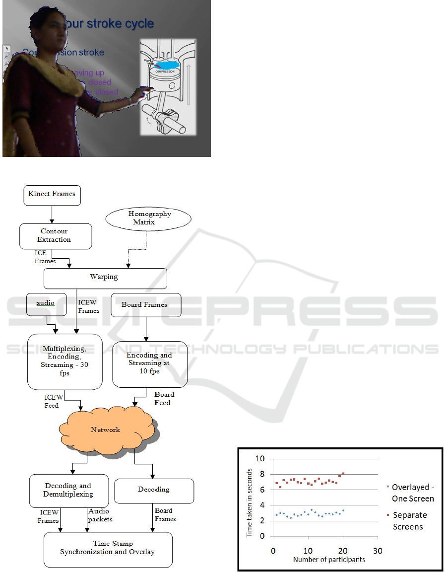
Figure 5: ICEW frame overlayed on Board frame.
Figure 6: Flow diagram for contour extraction and
overlay.
4 PERFORMANCE EVALUATION
For the performance evaluation about 20 participants
are made to identify the right number from the board
containing an array of numbers randomly pointed to
by the instructor. The experiment was conducted
over two sessions. The first session involved
displaying the instructor’s-stream and the board-
stream on separate screens. The second session was
conducted with one screen displaying the overlayed-
stream. The participants were made to identify the
number that the instructor is pointing to and press a
button on the keyboard indicating identification.
Upon key-press the instructor then points to a new
number and the procedure is repeated for 30
identifications. The system clocks the time taken for
each identification. In addition to this each student
has to write down the identified number just before
key press. Statistical analysis on the accuracy and
the time taken are calculated and presented below in
figures 7 and 8. Results indicate a marked
difference in the accuracy and speed with which the
participants are able to discern the area of focus
identified by the instructor’s gestures. Objective
analysis shows the speed of identification is
approximately 3 seconds when Overlayed video is
played back as compared to 7 seconds when the
participants are made to correlate between 2 screens.
Accuracy has a mean of 23.85 correct responses
with a variance of 16.344 for the first session. The
second session had a mean of 30 correct responses
with 0 variance.
Furthermore, subjective analysis of the
participants were taken, were they were asked to rate
their experience in a scale of 5 in terms of “ease of
discerning the area of focus by the instructors
gestures”. Session 1 obtained an average score of 1.6
while session 2 obtained an average score of 4.8.
Figure 7: Average time taken for identification for each
participant.
Instructor Contour Extraction and Overlay for Near-real Presence in e-Learning Systems
357
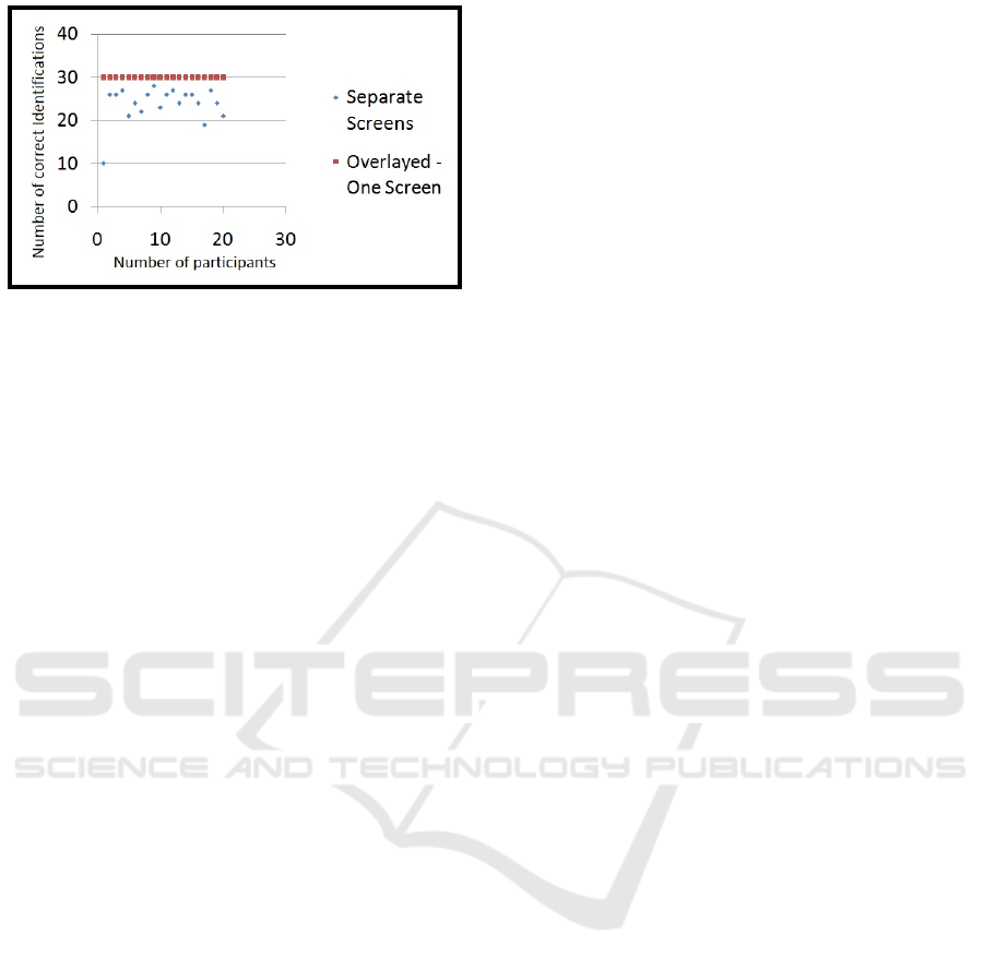
Figure 8: Accuracy of identification.
5 CONCLUSIONS
Results indicate a marked improvement in the speed
and accuracy with which the participants are able to
discern the area of interest on the board. This shows
the remote participants are able to follow the
instructors gestures over the board with ease.
ACKNOWLEDGEMENTS
We would like to express our gratitude to our
chancellor Mata Amritanandamayi for her
benevolent guidance. We also would like to thank
Sneha Mowad for helping us edit and proof read the
paper.
REFERENCES
Huettner, Brenda., 2008. Adobe Captivate 3: The
Definitive Guide. Jones & Bartlett Learning.
Bijlani, Kamal, et al. 2010. A-view: adaptive bandwidth
for telepresence and large user sets in live distance
education. Education Technology and Computer
(ICETC), 2010 2nd International Conference on. Vol.
2. IEEE.
Davison., Andrew., 2012. Kinect Open Source
Programming Secrets: Hacking the Kinect with
OpenNI, NITE, and Java: Hacking the Kinect with
OpenNI, NITE, and Java. McGraw Hill Professional.
Wolberg, George., 1990. Digital image warping. Vol.
10662. Los Alamitos: IEEE computer society press.
Wolberg, George., 1990. Digital image warping. Vol.
10662. Los Alamitos: IEEE computer society press.
Krishnamurthy, Sundar Narayan., 2011. Human Detection
and Extraction using Kinect Depth Images.
Bournemouth University.
Lowe, David G., 2004. Distinctive image features from
scale-invariant keypoints. International journal of
computer vision 60.2: 91-110.
Ramponi, Giovanni., 1999. Warped distance for space-
variant linear image interpolation. Image Processing,
IEEE Transactions on 8.5: 629-639.
Lavrov, Valeri., 2004. Screen recording system for the
windows desktop. Science and Technology, 2004.
KORUS. Proceedings. The 8th Russian-Korean
International Symposium on. Vol. 1. IEEE.
CSEDU 2016 - 8th International Conference on Computer Supported Education
358
