
Modelling CAD Models
Method for the Model Driven Design of CAD Models for Deep Drawing Tools
Robert Scheffler
1
, Sergej Koch
2
, Gregor Wrobel
1
, Matthias Pleßow
1
,
Christian Buse
2
and Bernd-Arno Behrens
2
1
Society for the Advancement of Applied Computer Science (GFaI), Berlin, Germany
2
Institute of Forming Technology and Machines (IFUM), Leibniz Universität Hannover, Garbsen, Germany
Keywords: Model-based Systems Engineering, SysML, Graphical Domain-Specific Languages, Meta-modelling, Sheet
Metal Forming, Parametric Three-dimensional Computer-Aided (3D CAD) Models.
Abstract: Designing a fully parametric CAD model of a sheet forming tool in a 3D CAD system expends temporal
and financial effort and thus engineers shy away from it. The Institute of Forming Technology and
Machines (IFUM) and the Society for the Advancement of Applied Computer Science (GFaI) are currently
developing a new method for the model driven design of deep drawing tools. The core of this method is a
graphical modelling language for the domain of deep drawing tools. Meta models of these tools allow the
generation of models which in turn can be transformed to parametric CAD models and completed by
geometric modelling. The new method makes the modelling of parametric relations and dependencies easier
and less error-prone.
1 MOTIVATION
The use of 3D CAD modelling in design and
construction processes is state of the art in modern
engineering. Interactive CAD models are created,
completed or expanded by means of a CAD system.
Such a product model includes geometrical data,
technological and functional information as well as
information about design and manufacturing process
(Feldhusen and Grote, 2013). For many years design
processes of deep drawing tools have also been
carried out by means of 3D CAD systems. Current
CAD systems allow for a direct integration of
product logic and design knowledge in the CAD
model. Furthermore, it is possible to create new
model variation and modification by changing
parameters. However, the design of fully
parametrical CAD models involves a precise
planning and modelling of parameter relations in and
between the individual parts and assemblies. Such
CAD model design allows a simple parameter and,
consequently, model change. Nevertheless, most
design engineers prefer to avoid parameter-based
design due to high time and cost pressure. As a
consequence, product logic and designer knowledge
will subsequently be integrated in the CAD model in
the form of equations and rules. This type of model
extension is very error-prone and could lead to
model instability (Bergholz and Sachse, 2009).
In particular, method planning and tool design in
sheet metal working companies are significantly
affected due to the high diversity of variants
(Griesbach, 2005).
Nowadays, CAD systems offer a high degree of
automation and thus simplify designer tasks.
However, in the earlier developing phases of sheet
metal tools these CAD systems fail to present the
functional interactions at the required level of
abstraction (Marchenko et al., 2011). The missing
support of these developing phases could prevent the
development of new and innovative tool concepts
(Prieur, 2006). In this case, the designer needs an
integrated CAD tool, which allows computer-aided
modelling with major and minor functions, operating
principles as well as structure and parameter
coherence. Suitable methods and support tools for
the simplified modelling of parameter-based
coherences do not exist.
In order to facilitate the reproduction of product
logic and of designer expertise, a new method for
the model-driven design of deep drawing tools has
been developed at the IFUM and the GFaI. The main
component of this method is a new graphical
modelling language based on Systems Modelling
Scheffler, R., Koch, S., Wrobel, G., Pleßow, M., Buse, C. and Behrens, B-A.
Modelling CAD Models - Method for the Model Driven Design of CAD Models for Deep Drawing Tools.
DOI: 10.5220/0005799403770383
In Proceedings of the 4th International Conference on Model-Driven Engineering and Software Development (MODELSWARD 2016), pages 377-383
ISBN: 978-989-758-168-7
Copyright
c
2016 by SCITEPRESS – Science and Technology Publications, Lda. All rights reserved
377

Language (SysML). This new modelling language
should expand the conventional CAD model to an
eXtended CAD (XCAD) model. By means of this
graphical language, parameter coherence could be
defined in earlier developing phases of deep drawing
tools. Thus, the conventional geometric modelling of
deep drawing tools could be replaced by applying
this new graphical language. This simplifies the
complexity of the parametric modelling of deep
drawing tools and thus the designer tasks.
2 STATE OF THE ART
2.1 Parametric 3D CAD Models
Market-leading 3D CAD systems, such as CATIA
V5, Solid Edge, Creo Parametric and Inventor
provide different approaches to creating geometric
3D CAD models of mechanical constructions. Here,
a differentiation is made between explicit and
parametric-associative modelling. In both modelling
methods, a 3D CAD model consists of a part or an
assembly of parts, and the visual 3D CAD model is
described by geometric parameters. In explicit
modelling there are no dependencies between
individual geometric parameters. This modelling
method is primarily used for customised individual
constructions with short development times. The
CAD system only saves part properties and topology
of the last modelling step (Schumacher, 2013).
During parametric-associative modelling, the
CAD system saves the genesis of the parts instead of
their geometries. These specific parts represent not
only object geometry, but also object attributes as
well as the creation history (Abulawi, 2012).
Parametric-associative modelling allows creating
parametric CAD models, which can be adapted to
planned modifications quickly and consistently.
Such CAD models consist of parameters, features
and their dependencies. In the context of CAD
systems a parameter is a variable by which the CAD
model can be controlled. Parameters can have
various data types and store integer values, float-
point numbers, truth values as well as strings (Vajna
et al., 2009). In parametric modelling a feature is
defined as an aggregation of geometry objects and
attributes (or parameters), which are used for the
common representation of functional elements. A
distinction is made between semantic and shape
features. A shape feature includes geometry
elements and their dimensioning parameters.
Additionally, a semantic feature stores technological
information, for example the hole tolerance H7.
Consequently, a feature contains the relevant
properties with their values as well as their relations
and constraints (Vajna et al., 2009).
The dependencies between parameters and CAD
elements such as features, parts or assemblies are
modelled in the form of constraints and relations.
These constraints and relations can be created as
functions and equations, but also as algebraic, logic
and semantic constraints (Marchenko et al., 2011).
2.2 Graphical Domain-Specific
Languages in Mechanical
Construction
Domain-specific languages (DSL) are formal
languages that are tailored for the use of a specific
domain. They are widely used in the form of textual
languages (e.g. Modelica) to model artefacts
(objects, facts, functions, behaviours) of the
individual domain. Graphical languages have been
established as well, the most widely used being
Unified Modelling Language (UML) and Systems
Modelling Language (SysML) as graphical domain-
specific languages for the domains Software
Engineering and Systems Engineering respectively.
While textual languages are usually described by
grammars, and it’s possible to specify graphical
languages by grammars (e.g. graph grammars) the
typical approach is to model the abstract syntax of a
language by defining a meta-model of the domain.
The meta-modelling of the languages UML and
SysML allows for specification and extension, so
that new DSL can be defined in addition to the
existing languages.
Graphical domain-specific languages (GDSL)
are already introduced into the domain of
mechanical construction: Hochgeladen and Vyas
explored the use of UML for the design of complex
assemblies and concluded that particularly the
knowledge embedded in rules and algorithms is
easier to grasp in the form of UML than in the
classic geometric construction in a CAD model
(Hochgeladen and Vyas, 2004). Au and Yuen
developed a graphical DSL for the modelling of
sculpt objects. Although these objects are defined by
their geometric representation the user works with
abstract features and their relations (Au and Yuen,
2000).
Other approaches focus on earlier stages in the
construction process, for example Andersson
developed a tool for the concept phase to create
geometric and non-geometric models (Andersson et
al., 1995). Wölkl and Shea examined the use of
SysML for the concept modelling in mechanical
MODELSWARD 2016 - 4th International Conference on Model-Driven Engineering and Software Development
378
construction and showed the utility of several
SysML diagrams (Wölkl and Shea, 2009). Peak and
Zingel used SysML to generate a model usable for
simulations even in the early design phase (Peak et
al., 2007). Albers and Zingel applied SysML based
functional modelling techniques to the product
development process of mechatronic systems
(Albers and Zingel, 2013a).
2.3 SysML and Model-based Systems
Engineering
The mentioned research and industrial projects
highlight the potential of SysML for the domain of
parametric construction. Several surveys have also
examined the low acceptance of the Model-Based
Systems Engineering (MBSE) approach in
mechanical construction, notably (Bone and
Cloutier, 2009) and (Albers and Zingel, 2013b). The
main challenge identified was the steep learning
curve for SysML and particularly the application of
concepts like inheritance that aren’t present in
mechanical construction. SysML models differ
considerably from the mechanical models (CAD
models) a designer is used to. Other challenges are
the complexity and usage of specific diagrams. In
the survey conducted by Albers and Zingel only
48% of the participants claim to have knowledge of
Constraint (i.e. Parametric) diagrams and only 4%
find them to be “crucial”. A common improvement
recommendation by those surveyed was to increase
the usability of the existing modelling software tools
instead of the SysML language itself, which was
also one of the recommendations by Bone and
Cloutier.
3 METHOD
In order to simplify parametric 3D modelling of
deep drawing tools, a new method for the model-
driven design of deep drawing tools has been
developed at the IFUM and GFaI.
The major idea of the new method is to create
eXtended CAD (XCAD) models outside of CAD
software in a tool better suited for modelling
parametric relations. XCAD models don’t need to be
fully congruent to CAD models; they contain
information about the structure of the modelled
tools, but no geometric information. Since modelling
languages like SysML come with a graphical
notation and have seen industry acceptance they
should be considered as resources for this task.
The proposed workflow for a designer of deep
drawing tools is to first create the main structure of
the tool by building elements and connections
between them. This is based on a meta-model of
deep drawing tools that is loaded in the background
of the prototype software. The focus of the prototype
is on relations as the most important parts of the
CAD models to be created. The user is extensively
supported by layout algorithms and interaction
helpers. After an XCAD model is created it can be
exported to a CAD software system, where it is
completed to a full CAD model. Typically,
geometric parameters would be set in the CAD
software, which is uniquely suited for this task.
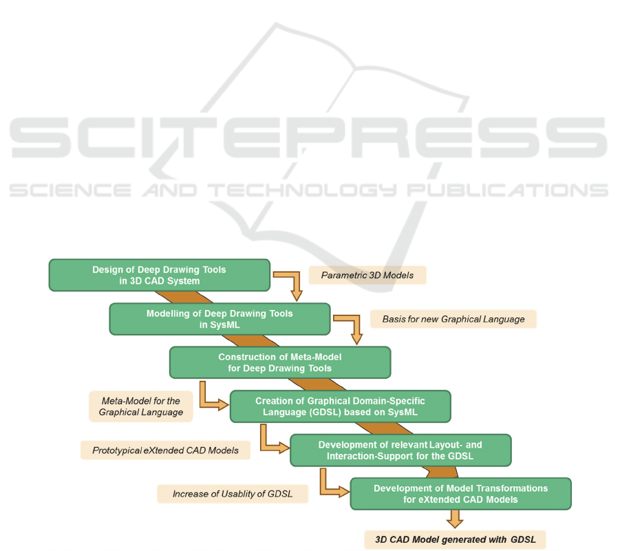
Figure 1: Development of the Method for Model-Driven Design of Deep Drawing Tools.
Modelling CAD Models - Method for the Model Driven Design of CAD Models for Deep Drawing Tools
379
The realised steps in developing the new method
are shown in Figure 1.
3.1 Analysis of CAD Models
Initially, deep drawing tools were selected for the
development of the new method and furthermore
their selection has been limited to three typical
geometries with varying complexity: round,
rectangular and trapezoidal geometries with flat
bottom area. In order to completely cover the
domain of deep drawing tools, single- and multiple-
acting deep drawing tools were modelled
parametrically in the 3D CAD system CATIA V5.
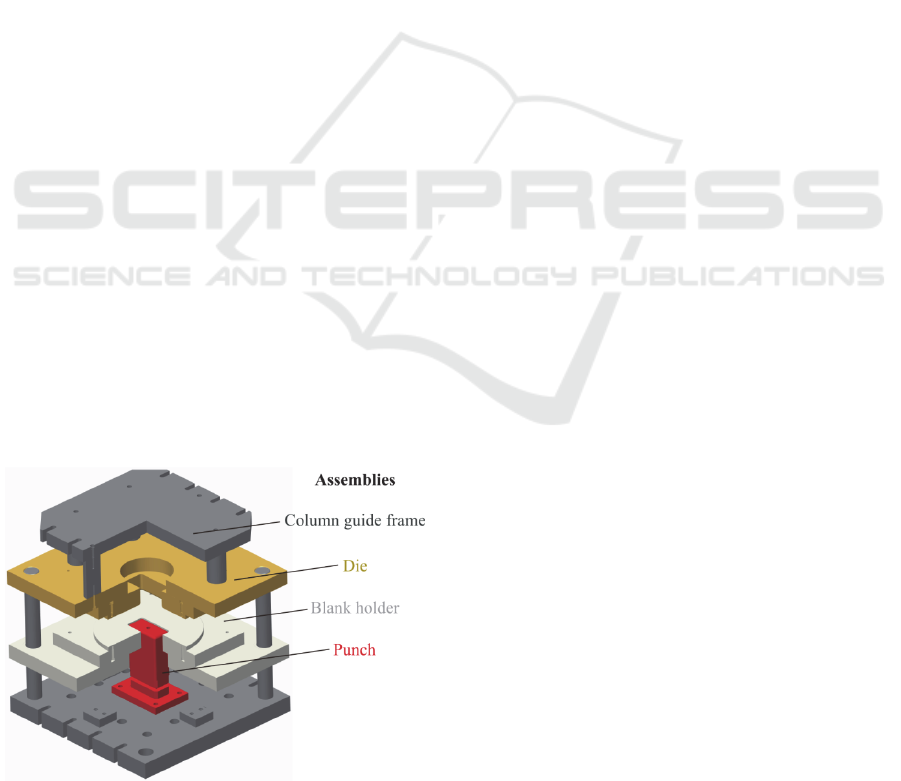
Figure 2 illustrates the 3D CAD model of a
single-acting deep drawing tool for a rectangular
cup. This tool consists of four assemblies, which
include several parts. Parametrical tool modelling
focuses on punch assembly since the punch is the
main forming component. Thus, the main
parameters in the form of length, width and height
are assigned to the forming punch. These three
parameters can be varied by the tool designer and
can consequently be called free parameters. These
are connected to the parameters of the other punch
assembly parts by corresponding relations. Thus,
this connection influences the geometry of the whole
assembly. The punch assembly is fixed on the upper
fixing plate and affects the column guide frame
assembly by the parameters and their relations. The
punch and the die are active tool elements, which
form the sheet metal part. Consequently, it is useful
to model the die assembly depending on the punch
assembly by corresponding relations. Figure 2 shows
that in this case the blank holder assembly is a
reversed copy of the die assembly. Therefore, the
blank holder assembly parameters depend on the die
assembly parameters.
Figure 2: CAD model of single-acting deep drawing tool.
In order to create a basis for formalising the
model data and the development of the meta-model,
development and construction documents in the
form of design drawings, requirement specifications
and part lists were created. In order to get an
overview of parameters and their dependencies in
the 3D CAD model, these were integrated in the
requirement specification documents in written
form.
3.2 Modelling in SysML
After designing the deep drawing tools as CAD
models, plain SysML was used to recreate these
models in order to get a better understanding of the
benefits and shortcomings of the model-based
approach. The diagrams used were Block Definition
Diagrams (BDD) for the hierarchical structure of the
CAD models and Parametric Diagrams (PD) for the
relations between model entities. Advanced SysML
concepts like profiles and stereotypes were also
explored and have proven helpful in adding
information without increasing diagram complexity.
The resulting diagrams are visual representations
of the parametric CAD models. The BDD hold
information about the structure of the models and a
rough outline of relations between them. Large
models are turned into very complex drawings that
are hard to read and understand clearly. A main
difference between the typical visualization of the
structure in a CAD software tool and a SysML
diagram is the representation of the composition
relation. CAD software often shows this as a tree
view, while SysML diagrams use relations
visualized by line connections. The abundance of
lines and the alikeness of different types of relations
make them hard to follow.
Studies on the readability of graphical languages
have found several important aesthetic criteria, most
notably the clear drawing of lines by avoiding
overlaps, crossings, bends and dense areas (Huang
and Eades, 2005; Ware et al., 2002). In a sufficiently
complex model essentially all of these criteria are
violated in BDD. While it is possible to separate
blocks into different diagrams this makes relations
between elements even more difficult to follow, as
they then cannot be contained in a single diagram.
While BDD can show that model elements are
related, the specific characteristics of these relations
are modelled in Parametric Diagrams. Surveys on
SysML use showed these to be among the most
puzzling diagram forms in SysML. For the domain
of parametric construction this is certainly true. To
model even the simplest constraint relations between
MODELSWARD 2016 - 4th International Conference on Model-Driven Engineering and Software Development
380
model elements (e. g. mathematical formulas on
geometric properties), one has to use several
diagrams that need to be read in a precise order to
understand the model. Modelling the large number
of relations usually present in a fully parametric 3D
CAD model by hand is extremely time-consuming.
The main benefit of SysML for the domain of
parametric construction is the standardization and
the availability of tools and implementations. The
easy extensibility through profiles is another
advantage. As a graphical language SysML has to be
considered severely lacking for this domain. The
visual representations of the information in CAD
models are needlessly complicated (PD) or so
complex that they suffer from poor readability
(BDD).
3.3 Building XCAD Models
Creating an XCAD model is an important step of the
method proposed in this paper and a main focus of
the prototype software to be developed. It can be
achieved in three ways:
1. The user can build the XCAD model entirely in
the software (by instantiating the meta-model).
2. The user can import a CAD model to be
extended into an XCAD model.
3. The user can import a SysML model to be
extended into an XCAD model.
Imports of existing CAD models were implemented
for the CAD software CATIA V5 in an earlier
research project (Marchenko et al., 2011). SysML
models can be imported through XML Metadata
Interchange (XMI) files, which are transformed into
the intermediate format by Extensible Stylesheet
Language Transformations (XSLT).
The basis for the modelling of XCAD models is
a meta-model of deep drawing tools. Borrowing
from language features of UML, this meta-model
was also created in the software prototype, using the
same interactions described below.
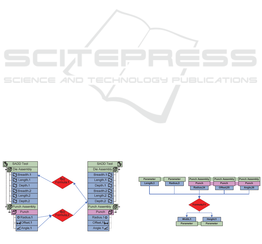
Figure 3: Dual Tree View (simplified snippet).
The prototype software uses a graphical language
that was developed to help users identify the
interconnectedness of relations in parametric 3D
CAD models. A Dual Tree View (see Figure 3)
contains two tree views for the same model and
displays relations between them in the middle. This
visualization allows the user to intuitively grasp the
hierarchical structure of the model, a feature that is
very prominent in the design of CAD models, while
at the same time putting relations between elements
into focus. Connecting lines can be kept relatively
short and mostly overlap and crossing free. As a
contrast to typical SysML diagrams both colours and
icons are used intensively to differentiate between
types of model elements. Dual Tree Views make use
of interactive user behaviour to show long chains of
relation connections.
Editing XCAD models consists of two main
tasks: Firstly the creation of the hierarchical
structure and secondly the modelling of relations
between the elements of this structure. The first task
is relatively straight forward and can be
accomplished with the usual set of interactions:
Adding elements, editing their properties, moving
and deleting elements. The software prototype
presents a graphical way to model relations: The
user connects elements by drawing a line, thus
creating a relation shell, which can then be filled out
in a second step. If, for example, a user wants to
create a geometric constraint between two parts of
an assembly, he would connect the two parts and in
the relation editing view all the (CAD) properties
and parameters of the two parts would be presented
to him. These can then be connected to a relation
element of the type “formula constraint”. The
relation editing view uses a graphical language
called Parameter Map (see Figure 4) that is
influenced by mind map visualizations. Here the
relation element is the centre of the view and the
input and output elements are positioned at the top
or the bottom of the layout area. The hierarchical
information about model elements is preserved by
the dynamic generation of symbols for elements as
stacked rectangles.
Figure 4: Parameter Map for single relation.
Modelling CAD Models - Method for the Model Driven Design of CAD Models for Deep Drawing Tools
381

The XCAD models created with the software
prototype can be exported in an XML format. To
complete the proposed design method it is necessary
to transform these models into a format that is
reusable by other software tools, e.g. the XML
scheme formats of modern CAD systems.
While SysML diagrams aren’t used in the design
of the meta-model and the creation of models, the
resulting models are still MOF compliant. That
means the output of the software prototype can be
XSL-transformed into an XMI format of a SysML
model. This allows a variety of systems modelling
tools to reuse the created XCAD models. In
particular, simulation tools can be used in rapid
prototyping before even using CAD software in the
design process. The proposed method therefore fits
nicely into other approaches to model driven design
and can be integrated with existing MBSE tools.
4 CONCLUSIONS
The goal of the presented research project was to
create a holistic, graphical and model-based method
for the concept stage of deep drawing tool design.
SysML was recognized as a potent instrument
for MBSE with rising acceptance and existing
applications in different stages of the engineering
process. SysML diagrams, particularly parametric
diagrams, were identified as a weak point of the
language regarding usability.
Analysing CAD models of deep drawing tools
helped creating a meta-model for these tools and on
the basis of the meta-model a new graphical domain-
specific language (GDSL) was created. It features
diagram types that allow for a more intuitive usage
by engineers and thus for a faster design iteration.
On the other hand, the relation to and reliance on
SysML was kept intact to facilitate the integration
with existing MBSE software tools.
A software prototype implements the GDSL and
its diagrams as well as various import and export
operations to showcase the method.
ACKNOWLEDGEMENTS
The authors thank the German Research Foundation
(DFG) for the financial support of the research
project “Method for the Model-Driven Design of
Deep Drawing Tools” (project numbers BE
1691/164-1 and PL 706/1-1).
REFERENCES
Abulawi, J., 2012. Dissertation: Ansatz zur Beherrschung
der Komplexität von vernetzten 3D-CAD-Modellen.
Hamburg
Albers, A.; Zingel, C., 2013a. Extending SysML for
Engineering Designers by Integration of the Contact &
Channel – Approach (C&C²-A) for Function-Based
Modeling of Technical Systems. In Procedia
Computer Science Vol. 16.
Albers, A.; Zingel, C., 2013b. Challenges of Model-Based
Systems Engineering: A Study towards Unified Term
Understanding and the State of Usage of SysML. In
Smart Product Engineering: Proceedings of the 23rd
CIRP Design Conference.
Andersson, K., Makkonen, P.; Persson, J.-G., 1995. A
proposal to a product modeling language to support
conceptual design. In CIRP Annals Vol. 44/1/1995.
Au, C.K.; Yuen, M.M.F., 2000. A semantic feature
language for sculptured object modeling. In
Computer-Aided Design 32.
Behrens, B.-A., Koch, S., Pleßow, M., Scheffler, R.,
Wrobel, G., 2014. Modellgetriebene Konstruktion von
Tiefziehwerkzeugen, In PLM IT Report 05.2014.
Bergholz, W., Sachse, P., 2009. Knowledge-based design:
how much support is expedient? International
Conference on Engineering Design, Stanford, USA.
Bone, M., Cloutier, R., 2009. The Current State of Model
Based Systems Engineering: Results from the OMG™
SysML Request for Information 2009, 8
th
Conference
on Systems Engineering Research, Hoboken, NJ.
Feldhusen, J., Grote, K.-H., 2013. Pahl/Beitz
Konstruktionslehre: Methoden und Anwendung
erfolgreicher Produktentwicklung. Berlin, 8. Auflage.
Griesbach, B., 2015. Innovationen im Werkzeugbau. 18.
Umformtechnisches Kolloquium, Hannover
Hochgeladen, R.; Vyas, P., 2004. Entwurf komplexer
Zusammenbauten mit UML. In CAD-CAM Report Nr.
3, Hoppenstedt Publishing GmbH Verlag.
Huang, W.; Eades, P., 2005. How People Read Graphs, in
APVis '05 proceedings of the 2005 Asia-Pacific
symposium on Information visualisation - Volume 45,
Australian Computer Society.
Marchenko, M., Behrens, B.-A., Wrobel, G., Scheffler, R.,
Pleßow, M., 2011. A New Method of Visualization and
Documentation of Parametric Information of 3D CAD
Models. In Computer-Aided Design & Applications,
8(3).
Peak, R. S.; Burkhart, R. M.; Friedenthal, S. A.; Wilson,
M. W.; Bajaj, M.; Kim, I., 2007. Simulation-Based
Design Using SysML Part 2: Celebrating Diversity by
Example. In INCOSE Intl. Symposium, San Diego.
Prieur, M., 2006. Dissertation: Functional Elements and
Engineering Template-based Product Development
Process. Application for the Support of Stamping Tool
Design, Karlsruhe.
Schumacher, A., 2013. Optimierung mechanischer
Strukturen, Springer-Verlag. Berlin Heidelberg.
MODELSWARD 2016 - 4th International Conference on Model-Driven Engineering and Software Development
382

Vajna. S., Weber, C., Bley, Z., Zeman, K., Hehenberg, P.,
2009. CAx für Ingenieure. Springer-Verlag, Berlin-
Heidelberg.
Ware, C.; Purchase, H.; Colpoys, L.; Mcgill, M., 2002.
Cognitive measurements of graph aesthetics, in
Information Visualization Volume 1 Issue 2, Palgrave
Macmillan.
Wölkl, S.; Shea, K., 2009. A Computational Product
Model for Conceptual Design using SYSML. In
Proceedings of the ASME 2009 International Design
Engineering Technical Conferences & Computers and
Information in Engineering Conference.
Modelling CAD Models - Method for the Model Driven Design of CAD Models for Deep Drawing Tools
383
