Two Approaches for Dense DSM Generation from Aerial Digital
Oblique Camera System
Massimiliano Pepe and Giuseppina Prezioso
Department of Sciences and Technologies, University of Naples “Parthenope”, Centro Direzionale Isola C4, Naples, Italy
Keywords: Oblique Camera System, DSM, Photogrammetry, GPU, SfM, Aerial Survey.
Abstract: In recent years, in photogrammetric field, have been developed technologies, which consist of multi digital
oblique camera, able not only to observe the same target from different angles, but also to determine, thanks
to appropriate dedicated software, the geometry. Of particular interest is the new oblique camera system
Leica RCD30 that combines vertical (nadir) and oblique cameras according to the “Maltese cross”
characteristic scheme. The purpose of this work is to verify the potential of the oblique imagery to provide
dense point clouds to realize Digital Surface Model (DSM) to high resolution, where for high-resolution
model is meant a representation of the observed scene with a ground sample distance (GSD) of less than
10cm. The dense Digital Surface Models are obtained through two different approaches, one that derived
from photogrammetric reconstruction based on graphic processing units (GPU) technique and multi-core
CPUs, the other from so-called Structure from Motion (SfM). To analyse the quality both of acquisition
systems that the model surface obtained from images, a case study on the Nöllen (Switzerland) area is
presented.
1 INTRODUCTION
The oblique camera system is designed for high
accuracy 3D city models (Zhang et al., 2004, Wang
et al., 2008), cadastral applications (Pepe et al.,
2012), cultural heritage field (Nocerino et al., 2013)
and for the realization of DSM (Le Besnerais, 2008;
Madani, 2012; Cavegn, 2014).
Especially for the production of DSM, the recent
development of dense image matching methods, by
deriving point clouds from imagery, provides an
efficient alternative at airborne LiDAR systems
(Fritsch et al., 2012). In fact, the first experiments
the 3D point clouds concerning by oblique camera
have shown the potential using sample image
processing algorithm and the very dense point
clouds can be filtered to obtain even digital terrain
models (Fritsch et al., 2013).
The actual oblique camera system comes in a
variety of configurations, which differ in the sensors
number, format, arrangement, mode of acquisition
and spectral sensitivity (Rupnik et al., 2014).
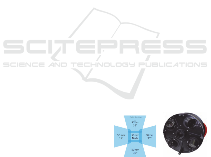
The oblique camera system taken into
consideration in this paper is the Leica RCD30
Oblique Penta System, which consists of five
cameras: four cameras inclined at 35° and arranged
according to an orientation north, south, west, east
and one nadir camera.
The shape of the ground coverage captured
simultaneously by the five cameras looks like a
“Maltese Cross” (Figure 1), a term first coined by
Gordon Petrie and Kenneth Smillie (Petrie, 2009).
The several cameras are mounted rigidly together
and their geometric configuration is calibrated to
enable accurate measurements in both the vertical
and oblique images.
Figure 1: Leica RCD30 Oblique Penta footprint with
RCD30 cameras.
The Leica RCD30 medium format camera is the
first 60 Mp camera able to acquire co-registrated
multispectral RGB and NIR imagery from one
Pepe, M. and Prezioso, G.
Two Approaches for Dense DSM Generation from Aerial Digital Oblique Camera System.
In Proceedings of the 2nd International Conference on Geographical Information Systems Theory, Applications and Management (GISTAM 2016), pages 63-70
ISBN: 978-989-758-188-5
Copyright
c
2016 by SCITEPRESS – Science and Technology Publications, Lda. All rights reserved
63
camera head (Wagner R., 2011). The features of
camera are reported in Table 1 (Leica Geosystems,
2015).
Table 1: Features of Leica RCD30 Oblique Penta.
CCD Size
8956
x
6708
p
ixels
Pixel Size
6
µ
m
D
y
namic Ran
g
e of CCD
73 dB
Resolution A/D Converter
14 bit
Maximum Frame Rate
(
Penta
)
1.8
s
ec
Motion Com
p
ensation
Mechanical, bi-directional
S
p
ectral Ran
g
e
Core
g
istere
d
Furthermore, this sensor connected with
GNSS/INS systems allows to accelerate the
workflow for the construction of elevation models.
In fact, the direct georeferencing (DG) system
correlates directly the data collected by a remote
sensing system to the Earth, by accurately measuring
the geographic position and orientation of the sensor
without the use of the traditional ground-based
measurements (Mostafa et al., 2001; Cramer, 2010;
Pepe et al., 2015a).
In addition to the acquisition system is necessary
define the appropriate processing technique of
image. The following section describes two
approaches.
The first coming from the computer vision
community and known as Structure From Motion
(SfM) algorithms while the second approach is
based on use of the GPU technology in combination
with multi-core CPUs which produces unmatched
processing speeds for the creation of geospatial data.
In the two approaches the quality of the DSM
depends by image of the photogram or better, within
the period of digital photogrammetry, by the Ground
Sampling Distance (GSD).
2 GSD, SCALE NUMBER AND
ACCURACY OF THE OBLIQUE
IMAGES
For each digital camera, the combination of the focal
length and pixel size determines a specific Ground
Sampling Distance (GSD).
In the case of vertical aerial flight, the
relationship between the GSD to the relative flight
altitude is (Neumann, 2008):
(1)
where:
GSD Ground Sampling Distance;
f Focal length;
S Pixel size;
H Relative flight altitude.
Considering the Leica RCD30 camera, using a focal
length of 50 mm and a pixel size of 6 µm, the
relation between the flight altitude and the GSD, in
the case of vertical aerial flight, is reported in Table 2.
Table 2: GSD at different flight altitude in vertical aerial
survey.
GSD
(cm)
Image
scale
Height
above
ground
(m)
Footprint
along track
(m)
Footprint
cross track
(m)
3 1:5000 250 20125 26870
5 1:8333 417 33542 44783
8 1:13333 667 53667 71653
10 1:16667 833 67083 89657
15 1:25000 1250 100625 134350
20 1:33333 1667 134167 179133
30 1:50000 2500 201250 268700
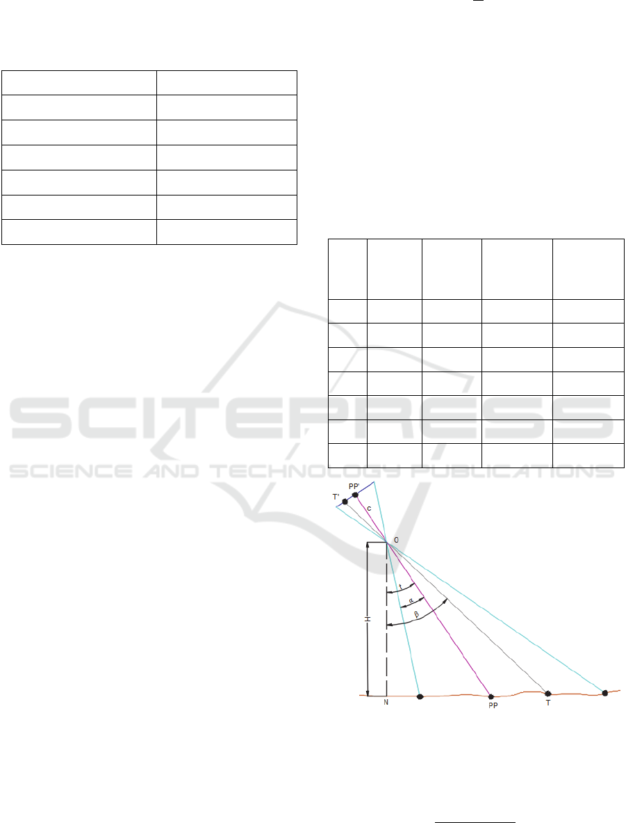
Figure 2: Parameters of oblique images (Hohle, 2008).
The scale within an oblique image (Figure 2)
depends of several parameters (Hohle, 2008), as
shown below:
cos
cos
(2)
GISTAM 2016 - 2nd International Conference on Geographical Information Systems Theory, Applications and Management
64
where:
m Scale at target point;
t Tilt angle;
β Angle between the viewing ray to a
target and the vertical;
Half of field of view.
The scale, m
PP’
, at principal point of image, PP’, is:
cos
(3)
By fixing the flight altitude (derived from Table 2
for each GSD) and choosing the parameters of the
photogrammetric system under consideration, the
scale at principal point of an image oblique assumes
the values given in Table 3.
Table 3: Scale at the principal point using the RCD30
system parameters.
Relative flight altitude (m) Image scale GSD (cm)
250 1:6104 4
417 1:10181 6
667 1:16285 10
833 1:20338 12
1250 1:30519 18
1667 1:40701 24
2500 1:61039 37
This means that at the same flight altitude occur
several GSD according to the cameras scheme and,
as can be observe from Tables 2 and 3, with
increasing altitude, the difference in GSD between
vertical and oblique aerial flight becomes more
important.
For example considering the flight altitude of
2500 m, if the flight of acquisition is vertical we get
a GSD = 30 cm, whereas if we choose the oblique
aerial flight we get a GSD = 37 cm.
Therefore, the GSD varies depending on the
geometry of the photogrammetric aerial oblique
flight and this is to be taken into account in the
planning phase of flight to obtain a specific
accuracy.
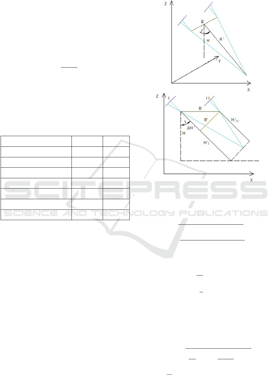
In the study the accuracy of oblique stereo image
occurs two cases: tilt across track (side-looking) and
tilt along track (forward-looking), whose geometry
in oblique stereo image is shown in figure 3 (Gerke,
2009).
Figure 3: Several geometry in oblique stereo image –
looking across track (up) and along track (down).
In the first case (tilt across track) the accuracy
value (Gerke, 2009) is:
≅
cos
,
sin
,
≅
sin
,
cos
(4)
where:
≅
(5)
,
≅
1
2
(6)
and indicating with:
parallax accuracy
′
(7)
In the second case (tilt along track) the accuracy
(Gerke, 2009) is:
≅
≅
sin
,
≅
(8)
Two Approaches for Dense DSM Generation from Aerial Digital Oblique Camera System
65
where:
p
x
parallax which needs to be computed for the
estimation.
≅
(9)
∆
≅sin
(10)
≅
(11)
≅
∆′
(12)
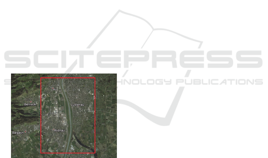
3 CASE STUDY
The nadir and oblique images are in Tiff format and
have been acquired on the Nöllen area, Widnau,
Switzerland (Figure 4).
The complete block consists of 625 images at 5
cm GSD and 300 images at 8 cm GSD with 30%
side overlap and 60% forward overlap. The external
orientation of every image captured, given in UTM
Zone 32 North, is calculated using the software
IPASCO and the Leica Photogrammetry Suite. The
misalignments and principal points of auto-
collimation (PPA), for the five different cameras,
have not been corrected in this original dataset. Of
this photogrammetric block has been selected a
limited area of particular interest and were chosen the
frames of the flight plan with GSD equal to 5cm.
Figure 4: A snapshot from Google Earth
®
showing the
location of the study area.
The file size of each aerial photo is about 487
MB. The processing was carried out using a PC with
the following configuration: Intel® Core™ 2.50
GHz CPU, 8 GB RAM.
3.1 DSM by using Structure from
Motion (SfM) Photogrammetry
Many tools designed for SfM applications collapse
due to the enormous number and size of the images
used in mapping projects. An idea to overcome this
limitation is to exctract from the block a
photogrammetric sub-block. In particular, have been
used 12 pictures of the block having a GSD of 5 cm
in order to obtain a higher resolution of the DSM
and orthophoto. The images have been chosen to
allow a stereoscopic coverage both in the sense of
the flight that transversely.
In this section, Agisoft Photoscan Pro software
(Agisoft, 2014) was used for 3D data processing.
This software works mainly on computer vision
based techniques. Structure from Motion (SfM), and
multi-view reconstruction techniques are the main
principles on which Agisoft creates the 3D model of
an object. In this software, both image alignment
and 3D model reconstruction are fully automated
(Sing, 2014). The 3D model reconstruction is
obtained in several straightforward processing steps.
Firstly Agisoft allows, through an algorithm
called “feature detection algorithm” by identify,
automatically, features in overlapping pictures and
match them. When the process is repeated for all
feature points in the dataset, the result is a sparse
point cloud which is a 3D approximation of the
scene in the pictures (Semyonov, 2011). The
alignment operation of the 12 images was performed
in 435 seconds. At this point, since both the original
camera positions and the cameras calibration are
known, the software can build a dense points cloud
(Van Damme, 2015) using a more computationally-
intensive algorithm. The Agisoft software offers
different options for to construct the dense points
clouds (Low, Medium, High, Very High), among
them the authors have chosen the “High”, because the
computer was not able to process in “Very High” mode.
Subsequently, in the “Build Mesh” step,
PhotoScan creates a surface mesh from the dense
point cloud. A representation of the geometry of the
images and the DSM generated in Agisoft
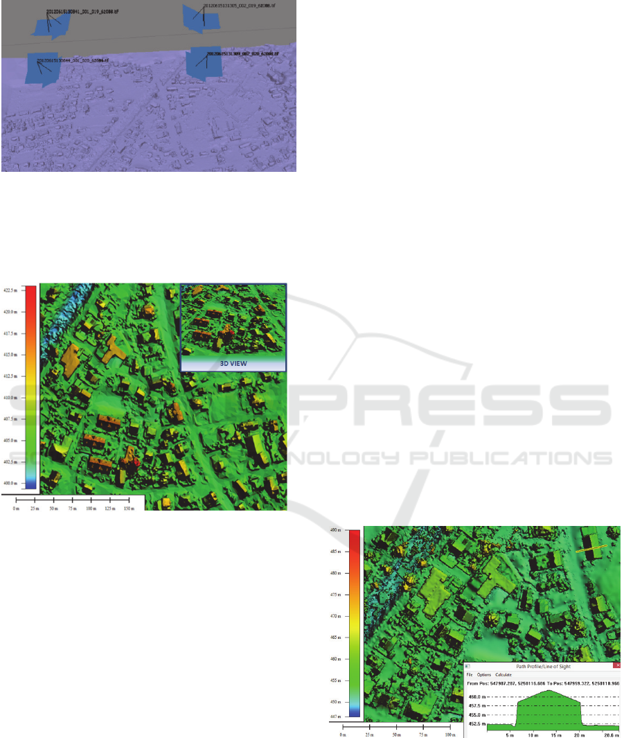
environment, is shown in Figure 5.
The software enable the export the point clouds
in several format; the LAS ASPRS file format allows
quickly to read and interpret the elevation ASCII data
and at the same time reduces the file size. However,
GNSS systems have led to the use of the ellipsoidal
height and, consequently, also the point clouds are
obtained in the ellipsoidal reference system. To
transform the ellipsoidal in ortometric height is
necessary to know a geoid undulation model. The
geoid undulations was taken from the geoid model
EGM2008 (Pavlis et al., 2008) and, with using a
software developed in Matlab® by the authors, has
been possible to transform the point clouds from
GISTAM 2016 - 2nd International Conference on Geographical Information Systems Theory, Applications and Management
66
ellipsoidal to orthometric height (Pepe et al., 2015b).
Figure 5: Camera positions and elevation model.
Subsequently the point clouds obtained were
converted into raster format GeoTiff with grid
10cmx10cm (Figure 6).
Figure 6: DSM of the study area obtained with Agisoft
Photoscan Pro.
3.2 DSM Obtained using GPU Method
In recent years is becoming more common, in
photogrammetric applications, the use of parallel
programming and computing power of the graphics
processing unit. In fact the modern graphic
processing units are not only powerful graphic
engines but also they are high level parallel
programmable processors with very fast computing
capabilities and high-memory bandwidth speed
compared to central processing units (CPU) (Sahin,
2012).
A commercial software that uses this approach is
Correlator3D ™ with which it is possible to realize a
DSM in two main phases: the aerial triangulation
and, subsequently, the generation of the model.
The first task for the production of the DSM is
the “Aerial triangulation”, which begins with the
extraction of the tie points. Correlator3D™
calculates the tie points by identifying, in adjacent
images, some feature points common and once done
that, these feature points are matched within each
flight line between adjacent images. The final step in
aerial triangulation is the “Bundle adjustment”. In
this process is performed, on all the images, a
minimization routine which determines, in iterative
mode, a unique correction for the exterior
orientation (EO) parameters in such a way as to
reduce the average residual between the tie points
and the projected points (Simactive, 2015). For
DSM generation is used the graphics processing unit
where the images are loaded into the GPU the
memory on a pair-by-pair basis, significantly
reducing the memory constraints on the system. The
process begins by loading a pair of images into the
GPU memory and a DSM patch, corresponding to
such pair, is created and stored on disk. This process
repeats until all the images have been processed. The
resulting overlapping DSM patches are then
optimized and merged in the following manner.
Within every DSM patch, to each point is associated
a weight based on a confidence measure. This
measure depends on different metrics including one
that assigns a weight to the elevation values as a
function of their distance from the center of the
DSM patches, this to reduce the potential occlusion
problems (Rotenberg, 2013). In the phase of the
Aerial Triangulation the average tie point residual
error was of 0.36 pixel and the required processing
time for obtain the DSM has been of some minutes.
Figure 7: DSM of the study area, by Correlator3D™
software, and profile elevation (ellipsoidal height).
The DSM realized by Correlator3D™, and
represented in Global Mapper environment (Figure 7),
shows the quality with which the software can
Two Approaches for Dense DSM Generation from Aerial Digital Oblique Camera System
67
describe the territory. In fact, from the elevation
profile it can be seen not only the typical shape of
the roofs and of the shape of the buildings, but also
the shape of the street gutter. Subsequently, in order
to check if the software shows limitations in the
treatment of numerous images, has been analysed a
block photogrammetric much wider of that
previously used. From this test it was found that the
software has been able to process 625 images, in
4725 sec. for the aerial triangulation processing and
81000 seconds for the production of the DSM.
3.3 DSM Comparison
The two DSM were compared with each other both
in terms of quantity and quality. From the
quantitative point of view means to compare the two
models both planimetrically that altimetrically. The
results obtained using some of the benchmark
showed a shift planimetric and altimetric contained
in the order of a few centimetres. The qualitative
comparison aims to analyse the ability, of the DSM,
to represent spatial objects (houses, dormers, trees,
etc.). The DSM, which has been produced, with
Correlator3D™ has allowed a (little) better
description of spatial objects than to Agisoft
software (Figure 8).
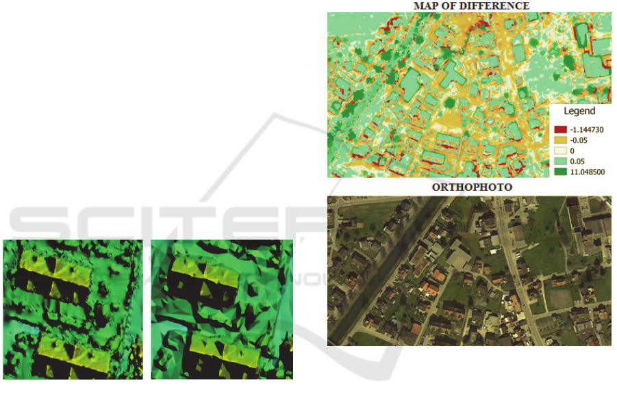
Figure 8: DSM comparison - Correlator3D™ (left) and
Agisoft (right).
Nevertheless qualitative and quantitative aspects
are interrelated. For example if the model obtained
with Agisoft is not able to represent a tree or a fence
means that this DSM, compared with that generated
by Correlator3D™, will get of the height differences
also important. In order to quantify the difference
between the two DSM, obtained with different
approachs, it has been employed the QuantumGIS
software, using the mathematical operator raster
“difference”.
From the comparison of the raster maps (Figure
9) can be deducted the following considerations:
the vast majority of the territory has a difference
contained in the value of 5 cm, demonstrating the
accuracy that can be achieved with both software
tested;
the only elements that showing notable
differences in height are the trees;
few and limited vertical shift occurred along the
edges of some buildings with the ability to
Correlator3D™ to produce a point cloud denser
and therefore represent in greater detail some
spatial objects; this means that a more dense
point clouds allows you to distinguish some
structures of the building, such as gutters,
chimneys and protruding elements.
Figure 9: Difference Map (meters) between the two
models (up) and orthophoto (down).
As regards processing times, the point clouds
generated by the software Correlator3D™ are
obtained in a time less than Agisoft. In addition the
first software showed a greater capacity to handle a
large number of images and, consequently, to
represent a wider area of the territory.
4 CONSIDERATION ON AERIAL
SURVEYS WITH OBLIQUE
CAMERAS SYSTEM
The traditional photogrammetric workflow overlap
(60% forward and 30% side overlap) creates
occlusion areas and reduces the redundancy of
GISTAM 2016 - 2nd International Conference on Geographical Information Systems Theory, Applications and Management
68
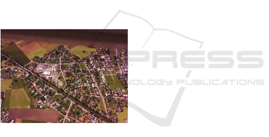
image information. Therefore it is desirable in the
flights on the cities, to increases the overlap of the
images, regardless of the type of restitution.
The high overlap allows a higher probability of
successful matches but, at the same time, a small
base line involves in a low accuracy of the height, as
shown in the formula 4 and 8. This means that,
wanting to ensure a thorough and detailed DSM, the
flight plan has to be well designed.
Also it is necessary to make an observation of an
operational character: the high spatial resolution of
the images requires a low-level flight. The low
altitude atmospheric air is influenced by topography
and the local temperature field. This means that a
rotation of the aircraft can affect not only the quality
of photogrammetry, but also cause the observation
of elements not belonging to scene, that is, in other
words, can happen of to photograph the underside of
the aircraft or the aircraft hatch (Figure 10). All this
results in saying that the flight preparation requires
appropriate meteorological conditions and a proper
study of the flight planning.
Figure 10: Elements of the aircraft visible in the photo.
5 CONCLUSIONS
Through the use of image from digital oblique
camera system, the two software examined have
provided, in an automatic way, dense point clouds
and of high accuracy, of particular utility in many
fields of geomatics.
The approach SfM for the production of DSM
using aerial digital image of medium format is
possible, but unfortunately limited to a few images.
The division into sub-blocks of the entire aerial
survey has allowed to overcome, at least in part, this
problematic. However, the processing time becomes
too long if the work area is very extensive. Instead,
the dense Digital Surface Models obtained through
photogrammetry reconstruction based on GPU
technology and multi-core CPUs has allowed to
obtain not only accurate point clouds but enabled to
manage a block photogrammetric with a lot of
images.
ACKNOWLEDGEMENTS
The authors thank Giovanni Abate and Jacques
Markram, Leica Geosystems, for the supply of
images and Michael O'Sullivan, Simactive, company
for software availability.
REFERENCES
Agisoft LLC, 2014. Agisoft PhotoScan User Manual:
Professional Edition, Version 1.1. http://www.
agisoft.ru/products/photoscan. Accessed 20/01/2015
Cavegn, S., Haala, N., Nebiker, S., Rothermel, M.,
Tutzauer, P., 2014. Benchmarking high density image
matching for oblique airborne imagery, The
International Archives of the Photogrammetry,
Remote Sensing and Spatial Information Sciences,
Volume XL-3, 5 – 7 September 2014, Zurich,
Switzerland.
Cramer, M., 2010. Direct georeferencing using
GPS/INERTIAL exterior orientations for
photogrammetric applications. International Archives
of Photogrammetry and Remote Sensing, Amsterdam,
Holland, 33, pp. 198 –205.
Fritsch, D., Kremer, J., Grimm, A., 2012. Towards All-in-
one Photogrammetry. GIM International, Vol. 26(4),
pp. 18-23.
Fritsch, D., and Rothermel, M., 2013. Oblique image data
processing: potential, experiences and
recommendations. Proc. 54th Photogrammetric Week,
pp. 73 – 88.
Gerke, M., 2009. Dense matching in high resolution
oblique airborne images. In: CMRT09: Object
extraction for 3D city models, road databases and
traffic monitoring: concepts, algorithms and
evaluation, Paris, 3–4 September 2009, pp. 77 – 82.
Höhle, J., 2008. Photogrammetric measurements in
oblique aerial images. Photogrammetrie
Fernerkundung Geoinformation 1, pp. 7 – 14.
Rotenberg, K., Simard, L., Simard, P., 2013. Dense DSM
Generation Using the GPU, Photogrammetric Week
2013, pp. 285 – 295.
Le Besnerais, G., Sanfourche, M., Champagnat, F., 2008.
Dense height map estimation from oblique aerial
image sequences. Computer vision and image
understanding, 109(2), pp. 204-225.
Leica Geosystems, 2015. http://www.leica-geo
systems.com. Accessed 01/03/2015
Two Approaches for Dense DSM Generation from Aerial Digital Oblique Camera System
69

Madani, M., 2012. Accuracy potential and applications of
Midas aerial oblique camera system, International
Archives of the Photogrammetry, Remote Sensing and
Spatial Information Sciences, Volume XXXIX-B1,
Melbourne, Australia.
Mostafa, M. R., Hutton, J., Lithopoulos, E., 2001.
Airborne direct georeferencing of frame imagery: an
error budget, The 3
rd
International symposium on
mobile mapping technology, Cairo, Egypt.
Neumann, K. J., Trends for digital aerial mapping
cameras, The International Archives of the
Photogrammetry, Remote Sensing and Spatial
Information Sciences, 2008.– Vol.XXXVII.– Part B1,
pp. 551 – 554.
Nocerino, E., Menna, F., Remondino, F., Saleri, R., 2013.
Accuracy and block deformation analysis in automatic
UAV and terrestrial photogrammetry – Lesson learnt.
ISPRS Annals of the Photogrammetry, Remote Sensing
and Spatial Information Sciences, Vol. II (5/W1), pp.
203 – 208.
Pavlis, N., K., Holmes, S., A., Kenyon, S., C., Factor, J.,
K., 2008. An Earth Gravitational Model to Degree
2160. EGM2008, General Assembly of the EGU,
Vienna, April 13 – 18/2008.
Pepe, M., Prezioso, G., Santamaria, R., 2012. Calcolo
della rendita presunta degli immobili fantasma:
contributo delle immagini aerofotogrammetriche da
multicamere digitali oblique. Atti 16a Conferenza
Nazionale ASITA, 6 – 9 novembre 2012, Fiera di
Vicenza, pp. 1091 – 1095.
Pepe, M., Prezioso, G., Santamaria, R., 2015a. Impact of
vertical deflection on direct georeferencing of airborne
images. Survey Review, Vol. 47, Issue 340, pp. 71 –
76.
Pepe, M., Prezioso, G., 2015b. A Matlab geodetic
software for processing airborne LIDAR bathymetry
data, ISPRS - International Archives of the
Photogrammetry, Remote Sensing and Spatial
Information Sciences, Volume XL-5/W5, 2015, pp.
167 – 170.
Petrie, G., 2009. Systematic oblique aerial photography
using multiple digital frame cameras.
Photogrammetric Engineering & Remote Sensing,
Vol. 75, No. 2, pp. 102 – 107.
Rupnik, E., Nex, F., Remondino, F., 2014. Oblique multi-
camera systems – Orientation and dense matching
issues, International Archives of the Photogrammetry,
Remote Sensing and Spatial Information Sciences,
Volume XL-3/W1, pp. 107 – 114.
Sahin, H., S., Kulur, 2012. Orthorectification by using
GPU method. International Archives of the
Photogrammetry, Remote Sensing and Spatial
Information Sciences 39, 165 – 170.
Semyonov, D., 2011. Algorithms used in PhotoScan.
Agisoft Community Forum. www.agisoft.com/forum/
index.php?topic=89.0. Accessed 6/08/2015
Simactive, 2015. http://www.simactive.com/en/software-
description Accessed 8/8/2015
Singh, S. P., Jain, K., Mandla, V.R., 2014. A new
approach towards image based virtual 3D city
modeling by using close range photogrammetry,
ISPRS Ann. Photogramm. Remote Sens. Spatial Inf.
Sci., II-5, pp. 329–337.
Van Damme, T., 2015, Computer vision photogrammetry
for underwater archaeological site recording in a low-
visibility environment, Int. Arch. Photogramm.
Remote Sens. Spatial Inf. Sci., XL-5/W5, pp. 231 –
238.
Wagner R., 2011. The Leica RCD30 Medium Format
Camera: Imaging Revolution, Photogrammetric week.
Stuttgart, Germany, pp. 89 – 95.
Wang, Y., Steve, S., Frank, G., 2008, Pictometry’s
proprietary airborne digital imaging system and its
application in 3D city modelling. International
Archives of Photogrammetry, Remote Sensing and
Spatial Information Sciences 37, pp. 1065 – 1069.
Zhang, Z., Wu, J., Zhang, Y., Zhang, Y., Zhang, J., 2004.
Multi-View 3D City Model Generation with Image
Sequences. International Archives of Photogrammetry
and Remote Sensing, Istanbul, Turkey, Vol. 34, Part 5,
pp. 351-356.
GISTAM 2016 - 2nd International Conference on Geographical Information Systems Theory, Applications and Management
70
