
Automating Activities in MDE Tools
Miguel Andr
´
es Gamboa and Eugene Syriani
DIRO, Universit
´
e de Montr
´
eal, Montr
´
eal, Canada
Keywords:
Workflow, Enactment, Domain-specific Modeling, Model Transformation, Fitts Law.
Abstract:
Model-Driven Engineering (MDE) is a victim of its own success: being able to quickly generate software tools,
many modeling tools exist today, but their usability is far from efficient. Complex processes and repetitive
tasks are often required to perform a modeling activity, such as creating a domain-specific language or creating
a domain-specific model. The goal of this paper is to increase the productivity of modelers in their every day
activities by automating the tasks they perform in current MDE tools. We propose an MDE-based solution
where the user defines a workflow that can be parametrized at run-time and executed. Our solution works for
frameworks that support two level metamodeling as well as deep metamodeling. We implemented our solution
in the MDE tool AToMPM. We also performed a preliminary empirical evaluation of our approach and showed
that we reduce both mechanical and cognitive efforts of the user.
1 INTRODUCTION
Model-Driven Engineering (MDE) has been advocat-
ing faster software development times through the
help of automation (Schmidt, 2006). MDE tech-
nologies combine domain-specific languages (DSL),
transformation engines and code generators to pro-
duce various software artifacts. Although some stud-
ies report success stories of MDE (Whittle et al.,
2014), some of the less satisfactory results include the
presence of a plethora of MDE tools. Each tool de-
fines its own development and usage process, which
is a burden on the user who needs to adapt himself to
every tool. To be successful, MDE needs tools that
are not only well adapted to the tasks to perform, but
also tools that increase the productivity of modelers
in their day-to-day activities.
Modeling tools and frameworks, such
as AToMPM (Syriani et al., 2013),
EMF (Steinberg et al., 2008), GME (Ledeczi
et al., 2001), and MetaEdit+ (Kelly et al., 1996),
provide many functionalities, such as DSL creation,
model editing, or model transformations. Although
based on common foundational principles, the
process for performing these tasks differs greatly
depending on the tool used. For example, to create
a DSL in AToMPM (AToMPM, 2013), the language
designer has to load the class diagram formalism and
graphically build the metamodel. He generates the
abstract syntax of the DSL from that metamodel by
loading the compiler toolbar. Then he has to load
the concrete syntax formalism and assign a concrete
syntax to each individual class and association
from the metamodel by drawing shapes. He then
generates the domain-specific modeling environment
by loading the compiler toolbar. In contrast, the steps
are different to create a DSL in EMFText (EMFText,
2014). The language designer first creates a new
project by specifying the project settings in the
wizard dialog. He then creates an Ecore diagram file
and graphically builds the metamodel. He then needs
to create a generator model from the metamodel
file. To define the concrete syntax, he creates a file
specifying the textual grammar. Once completed, he
executes the generators to create the domain-specific
environment that needs to be launched as a separate
Eclipse instance initiated from the generated Java
code. Many of these activities involve repetitive tasks
and a lot of user interactions with the user interface of
the MDE tool. The processes to follow are complex
for all users, whether they are language engineers
(i.e., MDE savvy) or domain-specific modelers
(i.e., end-users). They require heavy mental loads
and tasks that are error-prone. It is therefore manda-
tory to try to automate MDE tasks and processes
as much as possible, thus decreasing the accidental
complexity of the tools used and letting the user focus
on the essential complexities of the domain problem.
To solve this issue, tools can implement auto-
mated workflows for each MDE activity that involves
a complex process or repetitive tasks. Many of the
tools already partially support this with the help of wi-
Gamboa, M. and Syriani, E.
Automating Activities in MDE Tools.
DOI: 10.5220/0005760701230133
In Proceedings of the 4th International Conference on Model-Driven Engineering and Software Development (MODELSWARD 2016), pages 123-133
ISBN: 978-989-758-168-7
Copyright
c
2016 by SCITEPRESS – Science and Technology Publications, Lda. All rights reserved
123
zards (Steinberg et al., 2008) or scripts (MPS, 2015).
However, even these wizards become quite complex
offering too many options that the user has to man-
ually input each time he wants to repeat an activity,
as in Eclipse based tools. There are also several lan-
guages to define processes, such as SPEM (OMG,
2008), but do not support their execution (or en-
actment) natively. Other executable process lan-
guages like BPEL (OASIS, 2007) are too complex
for the tasks we want to achieve in modeling tools.
Workflow languages, such as UML activity diagrams,
can be enacted (Syriani and Ergin, 2012), but the
execution relies on programming individual actions
which hampers porting a process from one tool to
another. We therefore propose to define a DSL, in-
spired from activity diagrams, that fits exactly the
purpose of designing workflows for common tasks in
MDE tools. The tasks encompass simple operations,
such as opening, closing or saving models, and more
complex tasks, such as generating the artifacts for a
DSL. We noted that several tasks occur in different
workflows, especially common operations e.g., open
and close. Therefore we opted for a reuse mecha-
nism, where the user defines workflows that can be
parametrized at run-time to minimize the number of
workflows to create. Since our solution follows the
MDE paradigm, the execution of workflows is en-
tirely modeled through model transformation.
The paper is organized as follows. In Section 2,
we describe the details of our solution and discuss
how we solved challenges we faced. In Section 3,
we report on the implementation of our approach in
AToMPM. In Section 4, we perform a preliminary
empirical evaluation of the impact our approach has
on improving the user productivity in AToMPM. Fi-
nally, we discuss related work in Section 5 and con-
clude in Section 6.
2 DESIGN OF A REUSABLE
WORKFLOW LANGUAGE
We propose an MDE-based solution where the user
defines workflows that can be parametrized at run-
time and executed. In this section, we describe a DSL
that is adaptable to a specific modeling tool. We also
describe the general process of how to design reusable
workflows to semi-automate MDE activities. Further-
more, we discuss how to enact workflows using model
transformation.
Task
AutomaticTask
ManualTask
GenericTask
WFParams: string
RTParams@2: string
extension: string
location@2: string
SaveModel
EditModel
InitialNode FinalNode
DecisionNode
condition: Constraint
IterationNode
iterations: int = 1
condition: Constraint
JoinNodeForkNode
ControlNode
0..1 0..1
0..1
0..1
0..1
0..1
0..1
0..1
2..* 2..*2..*
*
*
**
1
1 1
1
11
message: string
duration: int =
executing: bool = False
∞
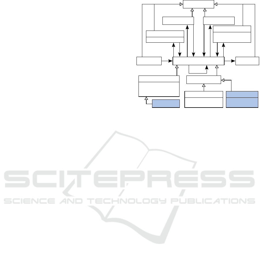
Figure 1: Generic metamodel of activities for modeling
tools.
2.1 Language for Semi-automated
Activities
We model the DSL for defining activities that can be
performed in MDE tools. An activity is composed of
tasks, to define concrete actions to be performed, and
control nodes, to define the flow of tasks. The meta-
model in Figure 1 resembles that of a simplification
of UML activity diagrams since, semantically, an in-
stance of this metamodel is to be interpreted similarly
to the control flow in UML activity diagrams. Addi-
tional well-formedness constraints are not depicted in
the figure e.g., a cycle between tasks must involve an
iteration node, there must be exactly one initial and
one final node.
There are different kinds of tasks in an MDE tool.
As for any modern software, there are tasks specific
to the user interface, such as opening, closing, and
saving models or windows. There are also tasks that
are specific to models, such as editing (CRUD opera-
tions) models, constraints, or transformations. There
are also tasks that are specific to the particular mod-
eling tool used, such as loading or executing a trans-
formation, generating code from a model, or synthe-
sizing a domain-specific environment from a DSL.
Furthermore, we want to automate users’ activities as
much as possible, therefore most of the tasks are auto-
matic: they do not require human interaction. For ex-
ample, loading a formalism to create a metamodel is
(e.g., Ecore in EMF or Class Diagrams in AToMPM)
is a task that can be automated, since the location of
that formalism is known. Shaded classes in Figure 1
(SaveModel and EditModel) are examples of tasks
that may vary from one MDE tool to another. Oth-
erwise, this is a generic metamodel implementable in
MODELSWARD 2016 - 4th International Conference on Model-Driven Engineering and Software Development
124

any MDE tool.
Nevertheless, some tasks are hard, even impossi-
ble, to automate and thus must remain manual. These
are typically tasks specific to a particular model, such
as deciding what new element to add in the model. A
message is specified to guide the user during manual
tasks. A maximum duration can also be specified to
limit the time spent on a manual activity.
An activity conforming to the metamodel starts
from the initial node and terminates at the final node.
Tasks can be sequenced one after the other. A deci-
sion node can be placed to provide alternative flows
depending on a Boolean condition evaluated at run-
time. Repetitions are possible with an iteration node.
The cycle ends when either the specified number of
iterations is reached or a terminating condition is sat-
isfied. Fork and join nodes provide non-determinism
when the order of execution of tasks is not relevant.
These correspond to the common basic control flow
patterns for workflows (Russell et al., 2006b). Al-
though not supported in our current implementation,
tasks may be executed concurrently, except if the con-
current tasks are manual.
2.2 Activities as Workflows
An activity model conforming to the metamodel in
Figure 1 represents a workflow that is to be executed.
One issue is that many tasks require parameters. For
example, the task SaveModel requires the location
of where to save the model (path and name) and
the extension to be used. The extension is generally
known from the context of the activity. For example, a
generic model ends with .ecore in EMF and .model
in AToMPM, but a domain-specific model may have
a specific extension in EMF. The designer of the ac-
tivity can thus set the value of this attribute at design-
time. However, the location of the model is generally
unknown to the activity designer because it is a deci-
sion often left at the discretion of the domain user. We
therefore distinguish between workflow parameters
that are fixed for all executions of the workflows and
run-time parameters that are specific to individual ex-
ecutions of the workflow. Hence, we need an interme-
diate model of the activities that is an instance of the
metamodel presented, but where some parameters are
left for further assignment. As explained in (Gonzalez
Perez and Henderson Sellers, 2008), the commonly
used technique of two-level metamodeling does not
allow us to represent this need.
An attractive solution is to apply techniques from
deep metamodeling (Lara et al., 2014), and in par-
ticular, the approach defining metamodels with po-
tency (Atkinson and K
¨
uhne, 2001). We assign a po-
tency of 2 to attributes representing run-time para-
meters and a potency of 1 to those representing work-
flow parameters, as depicted in Figure 1. This way,
the activity designer only needs to create one ac-
tivity for saving models with the extension set to
e.g., .model and the user can execute the workflow
only caring of the location where to save the model
and not bother what the right extension is. In this
setup, an instance of the activities metamodel in Fig-
ure 1 is a workflow. A workflow is itself the meta-
model of its instantiation at run-time. The enact-
ment of a workflow therefore consists in providing the
run-time parameters to a workflow and executing it.
These definitions are consistent with what the Work-
flow Management Coalition specifies (WMC, 1999).
2.3 Workflow Enactment by Model
Transformation
In this section, we describe how workflows are instan-
tiated with run-time parameters and executed.
2.3.1 Deep Instantiation
The issue with the above solution is that not
many modeling frameworks (e.g., AToMPM
1
and
EMF) support deep metamodeling with potency like
metadepth (de Lara and Guerra, 2010) or Mela-
nee (Atkinson and Gerbig, 2012) do. Therefore, we
propose a workaround to enact workflow by emulat-
ing deep metamodeling with potency for tools that do
not natively support it. The solution is to add a param-
eter class to the metamodel that is instantiated once
per workflow enactment. Its attributes are populated
dynamically for the enactment. They consist of all the
run-time parameters of every task in the activity. The
parameter object is used to generate a wizard prompt-
ing for all run-time parameters needed in the tasks of
a workflow.
Once a workflow has been created by the activity
designer, the user may opt to enact the corresponding
workflow. He creates a parameter object to specify
run-time parameters and executes the workflow. We
have modeled the enactment of workflows by model
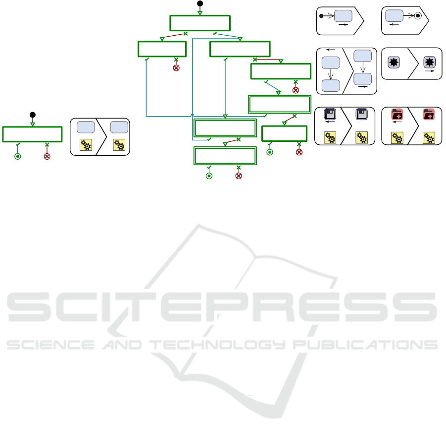
transformation. Figure 2 depicts the transformation in
MoTif (Syriani and Vangheluwe, 2011), a rule-based
graph transformation language. Rules are defined
with a pre-condition pattern on the left and a post-
condition pattern on the right. Actions on attributes
1
In (Van Mierlo et al., 2014), the authors proposed
a deep metamodeling solution for the Modelverse of
AToMPM, but no usable implementation was available at
the time of writing this paper.
Automating Activities in MDE Tools
125
LoadRTParams
:
LoadRTParams
for a in PreNode(1).getAttrs():
if '@2' in a:
PreNode(2).paramList.add(
'{' PreNode(1) ':' a[:-2] '}')
Task
1
2
Task
1
2
F
(a) Transformation for loading run-
time parameters.
: GetInitialTask
?
: GetNextTask
: EvalCtrlNode
: TerminateManTask
: ExecAutoTask
: ExecManTask
: GetNextCtrlNode
: IsFinalTask
?
TerminateManTask
PreNode(1).executing==True
PostNode(1).executing=False
current
1
1
GetNextTask
Task
Task
current
Task
Task
current
GetInitialTask
current
Task
IsFinalTask
current
Task
ExecuteSaveModel
_saveModelInNewWindow(
PreNode(2)[PreNode(1)]['location'])
current
1
2
1
2
ExecuteEditModel
PreNode(1).executing=True
current
1
2
1
2
B
B
(b) Transformation for executing a workflow.
Figure 2: Model transformations to enact workflows in MoTif.
are specified in Python. A scheduling structure con-
trols the order of execution of rules. The transforma-
tion in Figure 2(a) populates all attribute fields of the
parameter object (the icon with two gears) by visiting
each task in the activity model. The attributes names
and types are stored in a JSON format that is then used
to render a wizard prompting for their corresponding
values to the user. This is performed in a single FRule
that makes sure that each task is visit exactly once.
2.3.2 Execution
With all run-time parameters set, there are two ways
to execute the workflow. One is to transform the
workflow into a model transformation that gets exe-
cuted, as in (Lucio et al., 2013). Thus, a higher-order
transformation takes as input the workflow (activity
and parameter object), and generates a rule for each
task and schedules them according to the control flow.
This is possible in MoTif since rules and scheduling
are specified in separate models. Although this ap-
proach has the advantage to reuse built-in execution
mechanisms from the MDE tool, a new transforma-
tion must be generated for each workflow and, in par-
ticular, if the designer makes changes to the activity
model.
In this work, we have implemented an alterna-
tive solution: we define the operational semantics
of a workflow and execute it as a simulation. Fig-
ure 2(b) illustrates an excerpt of this transformation.
The left part depicts the overall scheduling logic of
the rules. The process starts from the task marked
with the initial node. Each task is executed in se-
quence by calling the corresponding API operation of
the MDE tool with the corresponding run-time para-
meters. We assume that the MDE tool offers an API
for interacting with it programmatically (e.g., JSON
API for AToMPM and Java API for EMF). If a con-
trol node follows the current task that was just exe-
cuted, then either the condition of the decision or iter-
ation node is evaluated, or a fork is created. In the
current implementation, tasks in different branches
between fork and join nodes are executed sequen-
tially. The rules inside the CRule EvalCtrlNode for
control nodes are not shown here. The simulation
ends when the final node is reached. The right part
of Figure 2(b) shows sample rules of the transfor-
mation. For example, the ExecuteSaveModel rule
shows how the SaveModel task is executed by calling
the saveModelInNewWindow operation in AToMPM.
The transformation uses the pivot current to keep
track of the current task to execute. For example,
the GetNextTask assigns this pivot to the next task
to perform.
This logic runs autonomously as long as there are
automatic tasks. However, manual tasks require in-
terruption of the transformation in real-time so that
the user can complete the task at hand and then re-
sume the transformation. Automating such a pro-
cess requires to be able to pause and resume the
transformation from the rules being executed. Al-
though some transformation languages support real-
time interruption (Syriani and Vangheluwe, 2008),
most do not. Therefore, as depicted in Figure 2(b),
we extend the logic to handle manual tasks sepa-
rately. If the next task to execute is manual, the cor-
responding rule simply flags the task as executing,
as rule ExecuteEditModel shows, and the trans-
formation terminates. The user notifies the MDE
MODELSWARD 2016 - 4th International Conference on Model-Driven Engineering and Software Development
126
tool that his manual task is complete by restarting
the transformation. Consequently, the transforma-
tion executes the first rule TerminateManTask which
resumes the execution from the task that was last
marked as executing. The executing attribute for
manual tasks allows the workflow model to keep track
of the last manual task executed after the transforma-
tion is stopped.
2.4 Extensions and Exceptions
The approach presented here is evolution safe. MDE
tools evolve with new features added. If a new fea-
ture is available via the API and is needed in an
activity, then there are only two steps the designer
is required to perform to support that feature. He
shall add a new sub-class of automatic or manual task
in the metamodel of Figure 1 and add a rule under
ExecAutoTask or ExecManTask in Figure 2(b) that
calls the appropriate API function to perform the op-
eration. ExecAutoTask (respectively ExecManTask)
is a BRule that contains all the rules to execute au-
tomatic (respectively manual) tasks. BRules execute
at most one of their inner rules unless none of them
are applicable. The modularity of this design reduces
significantly the effort of activity designers who wish
to provide additional tasks available via new features
of the MDE tool.
Although it is common to explicitly model excep-
tional cases in workflows (Russell et al., 2006a; Syr-
iani et al., 2010), we have decided not to do that at
the activity model level. Exceptions can only occur if
a task execution fails because the user is constrained
to do exactly what the workflow allows as next ac-
tion. In this version of our implementation, if an ex-
ception occurs, the workflow execution stops at the
failing task in the activity, as depicted by the circled
crosses in Figure 2(b). The user must then manually
recover from the error and restart the execution of the
workflow. Nevertheless, run-time parameters are re-
tained.
3 IMPLEMENTATION IN
AToMPM
We implemented a prototype in the MDE tool
AToMPM (Syriani et al., 2013), since it offers a
graphical concrete syntax for DSLs, which is best
suited for workflow languages, and a backdoor API
to programmatically interact with the tool in head-
less mode. Nevertheless, our approach can be im-
plemented in any MDE tool as long as it offers an
accessible API to perform operations that their user
JoinNode
ForkNodeFinalNodeInitialNode DecisionNode
Control nodes
OpenModel
SaveModel
LoadToolbar
Automatic tasks
GenerateAS GenerateCS
Parameters
Workflow execution
LoadActivity
ExecuteActivity
EditModelManualTask
Manual tasks
CompleteManual
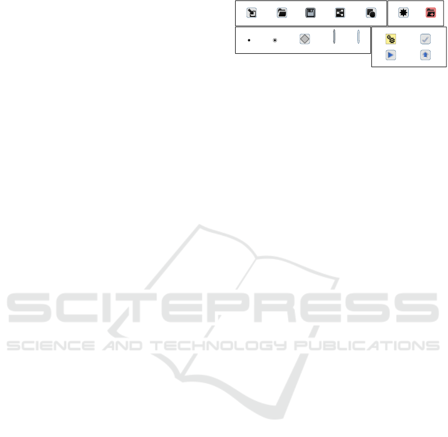
Figure 3: Concrete syntax of the activity DSL in AToMPM.
interface allows to. We implemented the activity DSL
following the metamodel in Figure 1. Figure 3 shows
the graphical representation used for each task, each
control node, and parameter object.
We analyzed several processes and noted the user
interactions needed to perform each task, e.g., cre-
ation of DSL. We had to decide on what level of gran-
ularity we want to present tasks. One option is to go
to the level of mouse movements (graphically mov-
ing objects), clicks (selections), and keystrokes (tex-
tual editing). Although this would enable us to model
nearly any user interaction AToMPM allows for, this
would make the activities very verbose and complex
for designers. We therefore opted for tasks to rep-
resent core functionalities instead. Subsequently, the
most common tasks we noted are opening models,
loading toolbars and formalisms, saving models, gen-
erating concrete and abstract syntax of DSLs, as listed
in Figure 3. All these operations can be automated,
since they require a location as run-time parameter.
SaveModel also has a workflow parameter for the ex-
tension of the model file. Additionally, a task to edit
models is needed, but cannot be automated since it is
up to the user to create or edit the model.
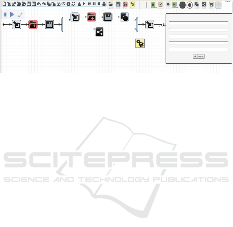
Our prototype is to be used as follows. The de-
signer defines workflows by creating instances of the
activity DSL. For example, Figure 4 shows the activ-
ity that specifies how to create a DSL and generate
a modeling environment for it in AToMPM. A user (a
language engineer in this example) then selects which
workflow he desires to enact. To set the run-time para-
meters, he pushes the ExecuteActivity button. This
creates an instance of the parameter object and pops
up a dialog prompting for all required parameters, fol-
lowing the transformation from Figure 2(a). Upon
pushing OK, the simulation (presented in Figure 2(b))
executes the workflow autonomously. When a manual
task is reached, a new AToMPM window is opened
with all necessary toolbars pre-loaded. A message
describing the manual task to perform is displayed to
the user and the simulation stops. After the user has
completed the task, he pushes the CompleteManual
button. Then, the window closes and the simulation
restarts.
Automating Activities in MDE Tools
127
Insert the parameters
LocationEditModel
LocationSaveModel
LocationEditModel
LocationSaveModel
LocationLoadToolbar
Figure 4: DSL creation example.
4 EVALUATION OF THE
IMPROVEMENT OF MDE
ACTIVITIES IN ATOMPM
4.1 Research Question
The goal of the experiment is to determine whether
the productivity of the user is increased when per-
forming complex or repetitive tasks. Thus, our re-
search question is “is the time for mechanical and
cognitive efforts of the user reduced when automating
activities?” Therefore, we conduct the experiment to
verify that these efforts are reduced when using our
approach versus when not.
4.2 Metrics
The total time T spent by a user to perform one ac-
tivity is one way to quantify the effort the user pro-
duces. T is mainly made up of the mechanical time T
m
(hand movements) and cognitive effort time T
t
(think-
ing time) of the user, thus T = T
m
+T
t
, assuming there
are no interruptions or distractions.
Since AToMPM only presents a web-based
graphical user interface and most interactions are
performed with a mouse, we can apply Fitts
Law (MacKenzie, 1992) to measure the time of
mouse movements t
FL
= a + b × log
2
(1 + D/S). D
is the distance from a given cursor position to the po-
sition of a widget to reach (e.g., button, text field) and
S is the smallest value of the width or height of the
widget. We denote T
FL
as the sum of all the t
FL
for
each useful mouse movement to perform one activity.
Another useful metric we noted for the mechani-
cal effort is the number of clicks c needed to complete
the activity. Relying on empirical data from an online
benchmark (Human Benchmark, 2015), the average
time to click reactively is 258 milliseconds. Thus we
denote T
c
= 258 ×c the time spent clicking during an
activity.
Therefore a rough estimate of the time spent on
mouse actions in an activity is T
m
= T
FL
+T
c
for every
straight line distance D between two clicks and the
size S of the widget at every even click.
Hence, we deduce the thinking time T
t
= T − T
m
as a rough estimate on the time the user spent thinking
during the activity.
Finally, we measure the complexity N of a task by
the number of automatic tasks it requires the user to
perform.
These metrics are far from accurate, but serve at
least as a preliminary evaluation of our approach to
discard the null hypothesis: T
m
, T
c
and T
t
are smaller
for performing an MDE activity in AToMPM using
workflows than without workflows.
4.3 Experimental Setup
We performed all experiments on a 15.6” laptop mon-
itor with a resolution of 1920 × 1080. The machine
was an ArchLinux virtual machine using 2 cores and
4GB of RAM, running on Windows 10 quad-core
computer at 2.4 GHz with 16 GB of RAM. Given this
performance, we neglected the computation time of
AToMPM triggered by each click. To keep a fair com-
parison, the experiments using the workflow did not
take into account the mouse activity and time spent
during manual tasks. This is the time after the simu-
lation terminates and before the notification from the
CompleteManual button is received.
4.4 Data Collection
To calculate t using Fitts law, the coefficients a and
b must be determined empirically. For that, we
MODELSWARD 2016 - 4th International Conference on Model-Driven Engineering and Software Development
128
recorded the straight line distances between mean-
ingful clicks (e.g., center of canvas to toolbar but-
ton) as well as different sizes of clickable elements
(e.g., model elements on the canvas) in AToMPM. We
recorded 12 distances ranging from 79 to 1027 pixels
and 5 sizes ranging from 20 to 305 pixels. We then
placed on an empty screen a point and a rectangle of
sizes and at distances that correspond to these mea-
surements. We measured the time it took to click on
the initial point and move the cursor as fast as possible
to click inside the opposite rectangle. This data col-
lection was performed by the first author who is an ex-
pert in AToMPM. We repeated each of the 57 cases 20
times (excluding those where D ≤ S). The maximum
variation in the same case was less than 9%. We de-
termined by regression analysis the values a = 166.75
and b = 155.93 with correlation R
2
= .9106 with a
median and average margin of error of 8%.
In our prototype, we implemented the five most
common tasks in AToMPM shown in Figure 3. There
is an infinite number of possible combinations of
these tasks because tasks can be repeated and the or-
der matters. Therefore, we reduced the number of
cases to only meaningful combinations of tasks in
AToMPM. We identified 4 meaningful for activities
with one task (compiling the concrete syntax requires
a model to be opened), 9 for activities with two tasks
(e.g., open then save model), 13 for activities with
three tasks, 4 for activities with four tasks, 5 for acti-
vities with five tasks, 3 for activities with six tasks,
and 3 for activities with seven tasks. Hence we ran
our experiments on 38 distinct activities varying up to
seven automatic tasks.
The most complex activity we evaluated is for
the creation of a DSL in AToMPM modeled with
the workflow in Figure 4, consisting of seven auto-
matic tasks. The activity starts by loading the Class
Diagram formalism. It lets the user manually cre-
ate the appropriate class diagram model to define
the metamodel. When the user completes that task,
the metamodel is saved (location provided at run-
time) and the abstract syntax is generated. Then
the ConcreteSyntax formalism is loaded and the
user creates the shapes for links and icons. When
the user completes that task, the concrete syntax
model is saved (name provided at run-time) and the
GenerateCS task generates the code for the new DSL
environment. Finally, the new formalism is loaded in
a new window showing the new generated DSL en-
vironment to the user. Note that in this situation, the
first LoadToolbar object does not require a run-time
parameter, but a workflow parameter for the location
of the Class Diagram formalism. We therefore sug-
gest to create two classes in the metamodel for the
0
5
10
15
20
25
30
35
40
45
1 2 3 4 5 6 7
T
m
(s)
N
Without workflow With workflow
(a)
0
10
20
30
40
50
60
70
80
90
100
1 2 3 4 5 6 7
T
t
(s)
N
No workflow Workflow
(b)
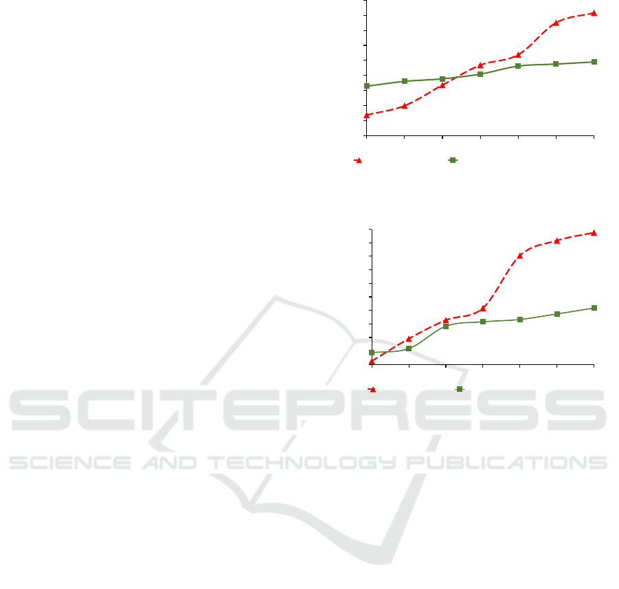
Figure 5: Mechanical (a) and cognitive (b) efforts with re-
spect to the number of tasks in an activity.
same task when we want to give the option to set ei-
ther run-time or workflow parameters depending on
the context.
4.5 Results
The two plots in Figure 5 report the time perfor-
mances for each case. We aggregated the times by
the number of tasks because there was very few vari-
ability between activities with the same number of
tasks: the highest coefficient of variability 20% was
obtained for activities with three tasks since this was
the most populous set, while all the others remained
under 5%. Both plots confirm that the use of work-
flows does reduce the time to perform the activity, as
the complexity of the activity increases.
The results obtained correspond to what one
would expect when adding automation in a develop-
ment process. The mechanical effort is greater when
using workflows for simple activities that have up to
three tasks. However, after that point, the mechanical
effort remains almost identical as the number of tasks
Automating Activities in MDE Tools
129

Table 1: Time measurements in seconds and improvements
when using workflows for N = 7 tasks.
T T
FL
T
c
T
m
T
t
No workflow 138 29 11 41 98
Workflow 66 18 6 24 42
Improvement 52% 38% 45% 41% 57%
increases. This behavior, depicted in Figure 5(a), is
due to the overhead to open the appropriate workflow
and set all run-time parameters. The reason why T
m
plateaus after N = 5 is that the only mechanical effort
needed is to specify additional run-time parameters.
However, this is done by typing the values with the
keyboard which we haven’t taken into account in this
experiment. When performing the experiments, we
noted that the slowest task performed manually was
for loading toolbars.
Figure 5(b) reports on the non-mechanical effort
needed by the user to perform each activity. We note
a trend similar to the mechanical effort. However,
the flip point where less effort is needed when using
workflows occurs as early as activities with more than
one task. The cognitive effort increases linearly for
activities with more than three tasks. An interesting
result is that, when not using workflows, the cogni-
tive effort is always greater than the mechanical effort
for N > 1 and that gap keeps on increasing as there are
more tasks. On the contrary, when using workflows,
the mechanical effort is greater for activities with up
to two tasks, but when the cognitive effort is greater
for N > 2, the gap remains almost identical. When
performing the experiments, we noted that most of
the time was spent searching on the screen to select
toolbars to load, even for an expert user who knows
exactly their locations.
To complement this information, Table 1 details
each metric for the most complex activities we eval-
uated. It shows that, although using workflows im-
proves all the metrics, the cognitive time is the most
improved component.
We conclude that our hypothesis is verified and
answer our research question: for the extent of the
experiments we conducted, the time for mechanical
and cognitive efforts of the user is reduced when au-
tomating activities with our approach by half.
4.6 Threats to Validity
There are several threats to the construct validity of
this preliminary evaluation. First, the metrics we used
are not sufficient to assess the complete mechanical
effort. Keystrokes can also be taken into account since
there is an effort needed to set the values of run-time
parameters. However, the length of the string of each
depends on the file paths of the host machines and
the operating system used. We discarded this met-
ric for its lack of generalization. Further mechanical
metrics could be used such as eye movements, but we
lacked the proper hardware to perform eye-tracking
experiments. We further mitigated these threats by
using Fitts Law to achieve an objective measure of
time mouse movements. We measured cognitive ef-
fort by considering it as all non-mechanical effort,
which is not a completely true statement. Otherwise,
this would have required more fine grained measure-
ments of brain activity. We also did not include the
time and effort for manual tasks, which may have a
negative influence on the results if they take longer
than the automatic tasks. The data collection was per-
formed by only one person, but this was only neces-
sary to calculate t since all other metrics are obtained
using Fitts Law, without needing to perform the acti-
vities. This threat only affects the absolute time, but
does not affect the improvement ratio.
With respect to threats internal validity, the selec-
tion and configuration of the tools for time measure-
ments has a weak influence on the results. We cali-
brated the parameters based on a pilot experiment and
our experience. However, this should not strongly af-
fect the time because we took care of configuring the
tools in a way that corresponds to the empirical data
from an online benchmark. We also pre-processed in-
consistent times (e.g., clicks outside target) in order
to eliminate false positives. Nevertheless, this only
reduces the chances that we can answer our research
question positively.
As far as threats to external validity are concerned,
the activities were obviously not sampled randomly
from all possible MDE tools activities, but we relied
on our knowledge in MDE tools. Hence, the set of
activities is not completely representative. The results
of this study can only be generalized to the extent of
AToMPM. Nevertheless, all five tasks we considered
are part of the most common activities in the major-
ity of MDE tools, such as EMF. We further mitigated
this threat by including tasks with different complex-
ity (i.e., Open Model vs Compile Abstract Syntax)
and focusing on their meaningful combinations.
5 RELATED WORK
A lot of work can be found in the literature on work-
flow definition and enactment (WMC, 2005; Mahmud
et al., 2013; Russell et al., 2005). In (Jacob et al.,
2012), the authors proposed a textual DSL for work-
flow definition that supports sequencing and iteration.
MODELSWARD 2016 - 4th International Conference on Model-Driven Engineering and Software Development
130

It is not meant to be enacted, but serves as specifica-
tion for subsequent code generators. Workflow enact-
ment has been particularly applied in process model-
ing.
Various techniques exist to service the execution
of workflows, such as distributing the execution on
the cloud (Alajrami et al., 2014; Martin et al., 2008).
However, none of these approaches models workflow
enactment explicitly as we did using model transfor-
mation.
We proposed a model transformation as a novel
workaround for tools that do not support deep instan-
tiation of metamodels. An alternative is to define
metamodels following the Type-Object pattern (John-
son and Woolf, 1996) where both types and instances
are explicitly modeled in the metamodel. This is sim-
ilar to the notion of clabject (Atkinson, 1997) which
generalizes this approach.
From an implementation point of view, the clos-
est work to ours automates transformation chains in
AToMPM (Lucio et al., 2013). They developed a
formalism transformation graph (FTG) that specifies
a megamodel indicating the transformations between
languages and a process model (PM) that specifies the
control and data flow to schedule the order of execu-
tion of model transformations. The execution of an
FTG+PM instance is modeled as a higher-order trans-
formation that converts the FTG+PM model into a
model transformation instance, whereas our approach
executes workflows by simulation. The authors also
distinguish automatic actions from manual ones, but
the latter are not modeled in the transformation.
Similarly to FTG+PM, Wires (Rivera et al., 2009)
supports the specification and execution of model
transformation workflows. Wires is graphical exe-
cutable language for ATL transformations that pro-
vides mechanisms to create model transformations
chains. Kepler (Lud
¨
ascher et al., 2006) is a tool to cre-
ate and execute scientific workflows. Since it is based
on the Ptolemy II multi-paradigm simulation system,
a coordinator must be hand-written in Java to define
the semantics of the workflow, unlike our approach
that makes use of model transformation.
In our approach, activities essentially encapsu-
late model management tasks. The Epsilon language
suite (Kolovos et al., 2008) can be used to perform
model management tasks such as CRUD operations,
transformations, comparisons, merging, validation,
refactoring, evolution, and code generation. To com-
bine and integrate these different tasks into work-
flows, the user defines Ant scripts. In our approach,
users define workflows in a DSL specific to the fea-
tures the MDE tool provides. As such, it reduces ac-
cidental complexity imposed by Ant and is accessible
to a broader set of users that do not know Ant. One
particular language is the Epsilon Wizard Language
(EWL) (Dimitrios S. Kolovos et al., 2007) whose pur-
pose is to refactor, refine, and update models. EWL
allows users to define wizards that serve as encap-
sulation of EOL scripts, the action language in Ep-
silon. Wizards are similar to activities in our case.
EWL provide feedback that can drive the execution
of a model management operation using a context-
independent user input. It is a command line user in-
put interface. In our approach, the user-input method
is a popup dialog with several parameters. Their ap-
proach has a more fine-grained wizard selection pro-
cess, since a wizard can have a guard that must be sat-
isfied in order to execute it. Nevertheless, EWL does
not support the explicit modeling of manual tasks.
6 CONCLUSION
In this paper, we presented a model-based environ-
ment for automating daily activities of language en-
gineers and domain-specific modelers. Designers de-
fine workflow templates conforming to a DSL to in-
crease the productivity of users. Users enact work-
flows to perform tasks automatically. Our framework
also supports the integration of manual tasks. The ex-
ecution of workflows is entirely modeled as a model
transformation, making it reusable and portable on
various MDE tools. Preliminary results of our pro-
totype indicate that, using workflows, users reduce
cognitive and mechanical effort to perform common
activities in the MDE tool AToMPM.
We are integrating more features of AToMPM in
our prototype to allow designers define workflows for
nearly any interaction process the tool can do. As
future work, we plan to implement this approach in
other MDE frameworks, such as EMF, in order to
further generalize the reusability aspect of the meta-
model of activities and their enactment by model
transformation. This will allow us to compare the im-
pact of workflows in the MDE development process
on different tools and, in particular, compare empiri-
cally our approach with EWL.
REFERENCES
Alajrami, S., Romanovsky, A., Watson, P., and Roth, A.
(2014). Towards Cloud-Based Software Process Mod-
elling and Enactment. In Model-Driven Engineering
on and for the Cloud, volume 1242 of CloudMDE’14,
pages 6–15.
Automating Activities in MDE Tools
131

Atkinson, C. (1997). Meta-modelling for distributed object
environments. In Enterprise Distributed Object Com-
puting Workshop, pages 90–101. IEEE.
Atkinson, C. and Gerbig, R. (2012). Melanie: Multi-level
Modeling and Ontology Engineering Environment. In
International Master Class on Model-Driven Engi-
neering: Modeling Wizards, MW ’12, pages 7:1–7:2.
ACM.
Atkinson, C. and K
¨
uhne, T. (2001). The Essence of Multi-
level Metamodeling. In Unified Modeling Language,
Modeling Languages, Concepts, and Tools, volume
2185 of LNCS, pages 19–33. Springer.
AToMPM (2013). AToMPM tutorial.
http://www.slideshare.net/eugenesyriani/atompm-
introductory-tutorial. Accessed: 2015-08-07.
de Lara, J. and Guerra, E. (2010). Deep Meta-modelling
with METADEPTH. In Objects, Models, Compo-
nents, Patterns, volume 6141 of TOOLS’10, pages 1–
20, Berlin, Heidelberg. Springer.
Dimitrios S. Kolovos, Richard F. Paige, Fiona A.C. Polac,
and Louis M. Rose (2007). Update Transformations in
the Small with the Epsilon Wizard Language. Journal
of Object Technology, 6(9):53–69.
EMFText (2014). EMFText screencast.
http://www.emftext.org/index.php/EMFText Getting
Started Screencast. Accessed: 2015-08-07.
Gonzalez Perez, C. and Henderson Sellers, B. (2008).
Metamodelling for Software Engineering. Wiley Pub-
lishing.
Human Benchmark (2015).
http://www.humanbenchmark.com/tests/reactiontime/
statistics.
Jacob, F., Gray, J., Wynne, A., Liu, Y., and Baker, N.
(2012). Domain-specific Languages for Composing
Signature Discovery Workflows. In Workshop on
Domain-specific Modeling, pages 61–64. ACM.
Johnson, R. and Woolf, B. (1996). The Type Object Pattern.
In EuroPLoP.
Kelly, S., Lyytinen, K., and Rossi, M. (1996). MetaEdit+
A fully configurable multi-user and multi-tool CASE
and CAME environment. In Conference on Advanced
Information Systems Engineering, volume 1080 of
LNCS, pages 1–21. Springer.
Kolovos, D. S., Paige, R. F., and Polack, F. A. C. (2008).
Novel features in languages of the epsilon model man-
agement platform. In Modeling in Software Engineer-
ing, pages 69–73. ACM.
Lara, J. D., Guerra, E., and Cuadrado, J. S. (2014). When
and How to Use Multilevel Modelling. ACM Trans-
actions on Software Engineering and Methodology,
24(12):1–46.
Ledeczi, A., Maroti, M., Bakay, A., Karsai, G., Garrett,
J., Thomason, C., Nordstrom, G., Sprinkle, J., and
Volgyesi, P. (2001). The generic modeling environ-
ment. In Workshop on Intelligent Signal Processing,
volume 17 of WISP ’01.
Lucio, L., Mustafiz, S., Denil, J., Vangheluwe, H., and
Jukss, M. (2013). FTG+PM: An Integrated Frame-
work for Investigating Model Transformation Chains.
In SDL 2013: Model-Driven Dependability Engineer-
ing, volume 7916 of LNCS, pages 182–202. Springer.
Lud
¨
ascher, B., Altintas, I., Berkley, C., Higgins, D., Jaeger,
E., Jones, M., Lee, E. A., Tao, J., and Zhao, Y. (2006).
Scientific Workflow Management and the Kepler Sys-
tem: Research Articles. Concurrency and Computa-
tion: Practice & Experience - Workflow in Grid Sys-
tems, 18(10):1039–1065.
MacKenzie, I. S. (1992). Fitts’ Law As a Research and
Design Tool in Human-computer Interaction. Hum.-
Comput. Interact., 7(1):91–139.
Mahmud, M., Abdullah, S., and Hosain, S. (2013). GWDL:
A Graphical Workflow Definition Language for Busi-
ness Workflows. In Recent Progress in Data En-
gineering and Internet Technology, volume 156 of
LNCS, pages 205–210. Springer.
Martin, D., Wutke, D., and Leymann, F. (2008). A Novel
Approach to Decentralized Workflow Enactment. In
Enterprise Distributed Object Computing, pages 127–
136. IEEE.
MPS (2015). JetBrains MPS.
https://www.jetbrains.com/mps/. Accessed: 2015-08-
07.
OASIS (2007). Web Services Business Process Execution
Language, 2nd edition.
OMG (2008). Software & Systems Process Engineering
Metamodel specification, 2.0 edition.
Rivera, J. E., Ruiz Gonzalez, D., Lopez Romero, F.,
Bautista, J., and Vallecillo, A. (2009). Orchestrat-
ing ATL Model Transformations. In Proceedings of
MtATL, volume 9, pages 34–46.
Russell, N., van der Aalst, W., and ter Hofstede, A. (2006a).
Workflow Exception Patterns. In Advanced Infor-
mation Systems Engineering, volume 4001 of LNCS,
pages 288–302. Springer.
Russell, N., van der Aalst, W., ter Hofstede, A., and
Edmond, D. (2005). Workflow Resource Patterns:
Identification, Representation and Tool Support. In
Advanced Information Systems Engineering, volume
3520 of LNCS, pages 216–232. Springer.
Russell, N., van der Aalst, W., ter Hofstede, A., and Mul-
yar, N. (2006b). Workflow Control-Flow Patterns: A
Revised View. Tech. report BPM-06-22, BPM Center.
Schmidt, D. C. (2006). Model-Driven Engineering. IEEE
Computer, 39(2):25–31.
Steinberg, D., Budinsky, F., Paternostro, M., and Merks, E.
(2008). EMF: Eclipse Modeling Framework. Addison
Wesley Professional, 2nd edition.
Syriani, E. and Ergin, H. (2012). Operational Semantics
of UML Activity Diagram: An Application in Project
Management. In RE 2012 Workshops, pages 1–8.
IEEE.
Syriani, E., Kienzle, J., and Vangheluwe, H. (2010). Ex-
ceptional Transformations. In Theory and Practice of
Model Transformation, volume 6142 of LNCS, pages
199–214. Springer.
Syriani, E. and Vangheluwe, H. (2008). Programmed Graph
Rewriting with Time for Simulation-Based Design. In
Theory and Practice of Model Transformation, vol-
ume 5063 of LNCS, pages 91–106. Springer.
Syriani, E. and Vangheluwe, H. (2011). A Modular Timed
Model Transformation Language. Journal on Soft-
ware and Systems Modeling, 12(2):387–414.
MODELSWARD 2016 - 4th International Conference on Model-Driven Engineering and Software Development
132

Syriani, E., Vangheluwe, H., Mannadiar, R., Hansen, C.,
Van Mierlo, S., and Ergin, H. (2013). AToMPM: A
Web-based Modeling Environment. In Invited Talks,
Demonstration Session, Poster Session, and ACM Stu-
dent Research Competition, volume 1115 of MOD-
ELS’13, pages 21–25. CEUR-WS.org.
Van Mierlo, S., Barroca, B., Vangheluwe, H., Syriani, E.,
and K
¨
uhne, T. (2014). Multi-Level Modelling in the
Modelverse. In Workshop on Multi-Level Modelling,
volume 1286 of MULTI ’14, pages 83–92. CEUR-
WS.org.
Whittle, J., Hutchinson, J., and Rouncefield, M. (2014). The
State of Practice in Model-Driven Engineering. IEEE
Software, 31(3):79–85.
WMC (1999). Terminology and glossary. Technical Report
WFMC-TC-1011, Workflow Management Coalition.
WMC (2005). Process Definition Interface – XML Process
Definition Language 2.00. Technical Report WFMC-
TC-1025, Workflow Management Coalition.
Automating Activities in MDE Tools
133
