
A Data Extraction Process for Avionics Systems’ Interface
Specifications
Hassna Louadah
1
, Roger Champagne
1
, Yvan Labiche
2
and Yann-Gaël Guéhéneuc
3
1
École de Technologie Supérieure (ÉTS), Montreal, Canada
2
Carleton University, Ottawa, Canada
3
École Polytechnique de Montréal, Montreal, Canada
Keywords: Interface, Interface Control Documents, Avionics Systems, IMA.
Abstract: Avionics systems, along with their internal hardware and software components interfaces, must be well
defined and specified (e.g., unambiguous, complete, verifiable, consistent, and traceable specification). Such
a specification is usually written in the form of an Interface Control Document (ICD), and represents the
cornerstone of the avionics system integration activities. However, there is no commonly accepted language
to define and use these ICDs and no common definition of what an ICD is or should contain. Indeed, avionics
companies define their own, proprietary ICDs and processes. In this paper, we first identify the pieces of
information that an ICD should contain for both federated and IMA open systems. Then, we propose a data
extraction process that enables better understanding and more efficient extraction of open avionics systems
interface specifications, and provides a clearer vision on the information needed to build a model driven
solution for modeling avionics system interfaces, our long-term goal. We validate this process by applying it
on a set of open avionics sub-system standards and the results have shown its feasibility.
1 INTRODUCTION
The beginning of the 20th century was marked by the
advent of the powered flight in 1903 and, ever since,
the aviation technology has continuously progressed
in all fields leading to the construction of today’s
aircrafts (Spitzer et al., 2014).
Up to the 90s, avionics systems followed a classical
federated architecture in which each function uses
dedicated Line Replaceable Units (LRU), each having
its own resources (computing, communication and I/O
services) (Watkins and Walter, 2007), (Moir et al.,
2013). However, with the evolution of avionics
systems requirements and technological progress,
these systems have become more and more complex.
This increasing complexity, combined with economic
concerns, have led to a wave of innovations unleashed
by the design of a new modular architecture
documented in ARINC-651 (AEEC, 1997a) “Design
Guidance for Integrated Modular Avionics” (Louadah
et al., 2014).
The aerospace industry is currently transitioning
and abandoning the traditional federated architectures
in favor of Integrated Modular Avionics (IMA)
(Louadah et al., 2014). An IMA architecture makes
use of shared computing resources so that resources
duplicated in each federated LRU are replaced by a
set of common IMA resources (Watkins and Walter,
2007).
An interface in a federated architecture is
described as a physical interface to a box and the
description of this interface refers to the
documentation of interwiring and data flow between
boxes. In contrast, in an IMA architecture, the
interfaces are not described by physical interfaces
only but also by logical system boundaries where data
is exchanged between virtual systems within the
common shared resources (Watkins and Walter,
2008). Hence, describing interfaces in an IMA
architecture requires more details, including all
component interfaces of the hosted applications (such
as processing requirements) and their common
shared resources (such as performance capabilities)
(Watkins and Walter, 2008), (RTCA, 2005).
Whether federated or IMA architecture is used,
the proper integration of various components requires
detailed specification and description of their
interfaces. Such specifications are usually described
in an Interface Control Document (ICD). Avionics
systems integration based on their ICDs is
544
Louadah, H., Champagne, R., Labiche, Y. and Guéhéneuc, Y-G.
A Data Extraction Process for Avionics Systems’ Interface Specifications.
DOI: 10.5220/0005745905440554
In Proceedings of the 4th International Conference on Model-Driven Engineering and Software Development (MODELSWARD 2016), pages 544-554
ISBN: 978-989-758-168-7
Copyright
c
2016 by SCITEPRESS – Science and Technology Publications, Lda. All rights reserved
challenging due to the absence of a commonly
accepted language to define and use them.
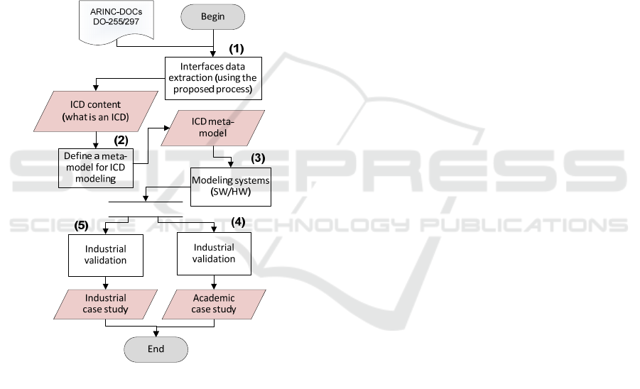
Our research project, depicted in Figure 1, aims to
develop reliable and cost-effective mechanisms to
produce and manage ICDs. The ultimate goal of this
project is to provide innovative tools to system
engineers, allowing them to efficiently integrate
equipment from different suppliers described by their
ICDs, when building avionics systems. To do so, our
main idea consists in leveraging the strengths of
model-driven engineering to the development, use
and verification of ICDs, in order to ensure
unambiguous description and representation of
interfaces and ICDs, and enable automatic
verification and analysis of interfaces (Louadah et al.,
2014).
Figure 1: Research project steps.
As a first step towards this goal, we must
accurately capture the information required to
properly define ICDs. In this paper, we concentrate
exclusively on this first step (process (1) of Figure 1)
by proposing a data extraction process, built upon
open avionics standards in both federated and IMA
systems, to assist the interface specification process
of avionics systems. In fact, there exist two types of
avionics systems architectures, open and closed,
depending on whether they are based on proprietary
interfaces or open standards (Watkins and Walter,
2007), (Watkins, 2006a, 2006b). This paper deals
with open systems only, as we do not have access to
proprietary ones. As there is no common definition of
what an ICD is or should contain, we exploit open
avionics standards of both federated and IMA
systems, which contain both ICD-related and non-
ICD related information.
The work described in this paper can be useful for
researchers from both academia and industry and its
application domain is mainly twofold. On the one
hand, it enables better understanding and more
efficient extraction process of open avionics systems
interface specifications. On the other hand, it provides
a clearer vision on the information needed to build a
model-driven solution for modeling avionics systems
interfaces.
The remainder of this paper is structured as
follows. We give an overview on avionics systems
and their related interfaces in Section 2. We present
and discuss the example used in this paper in
Section 3. We describe the data extraction process in
Section 4, followed by the results of its validation
through a use case in Section 5. Finally, we conclude
the paper in Section 6.
2 BACKGROUND
We now provide a snapshot of the avionics system
evolution, followed by a presentation of the main
differences between federated and IMA avionics
systems as well as the interfaces that each of them
presents.
2.1 Avionics Systems
During the 80s and early 90s, avionics systems
followed federated architectures where each function
used dedicated Line Replaceable Units (LRU), each
having its own resources (computing, communication
and I/O services) (Spitzer et al., 2014). Federated
architecture defined avionics systems as a set of
distributed, interrelated and independent functions
(Watkins and Walter, 2007). The LRU, along with its
embedded application software, was generally
designed and provided by one supplier (Moir et al.,
2013).
In the military context, the federated architecture
was adopted by using the bidirectional MIL-STD-
1553B data bus. Instead, the civil community chose
to use ARINC-429 (AEEC, 2012), which represents
the most used data bus in the civil context since its
introduction in the 1980s (Moir et al., 2013).
Along with the increasing complexity of avionics
systems and economic concerns, the avionics industry
witnessed the inception of a new approach, called
A Data Extraction Process for Avionics Systems’ Interface Specifications
545

Integrated Modular Avionics architecture (IMA), to
reduce cost, weight, and volume while taking
advantage of technological advances. In an IMA
architecture, applications can be hosted and
collocated on the same common resources.
The ARINC-653 “Avionics Application Software
Standard Interface” (AEEC, 2010) defines
standardised interfaces between hosted applications
and the underlying RTOS (Real Time Operating
System). In addition, it guarantees a spatial and
temporal segregation between applications by using
the partitioning mechanism and thus avoiding error
propagation between partitions (Spitzer et al., 2014),
(Cook and Hunt, 2007). An IMA architecture is
usually based on an ARINC-664-P7 (AEEC, 2009a)
communications network, known as Aviation Full
Duplex (AFDX). Other communication mechanisms
can also be used, such as in the Boeing 777, which
uses ARINC-629 as a data bus.
2.2 Avionics Systems Interfaces
Nowadays, both IMA and federated architectures are
used when building avionics systems, sometimes
together. The proper integration of avionics systems’
components requires detailed specification and
description of their interfaces, which are usually
described in ICDs. This integration of avionics
systems, based on their ICDs produced by different
suppliers with different formats and content, is a
challenging task due to the lack of a commonly
accepted language to define and use them. To
overcome these issues and as a first step toward the
automation of ICDs related activities, we must
accurately capture the information required to
properly define them. Determining the appropriate
information to capture is the ultimate objective of this
paper.
An interface in a federated system is usually
described as a physical interface to a box (i.e., LRU),
the inputs/outputs it presents as well as the protocol it
uses. Instead, an IMA component presents logical
interfaces that lie between virtual systems and the
shared common resources (Watkins and Walter,
2008). The interfaces between the hosted applications
and their computing resources, which were hidden in
federated systems (internal interface and supplier
proprietary), are now exposed interfaces in an IMA
system.
A hosted application interface can be described by
its inputs/outputs and their attributes (describing its
interactions with other hosted applications), the
protocols it uses as well as its resource requirements
(AEEC, 2010, Section 3.1.2). An IMA platform
presents physical interfaces, but also interfaces to the
hosted applications, that are mainly described by the
platform performance capabilities and limits. The
platform performance attributes can be found and
extracted from DO-255 (RTCA, 2000, tables 1-5).
3 EXAMPLE DESCRIPTION
To illustrate and validate our proposed data extraction
process, we introduce in this section an avionics
system as a running example. This system is depicted
in Figure 2 and consists of a flight management
system and a few other avionics systems that must
interface with it.
We have chosen the flight management system
because it represents the core of every avionics
system while the other systems are chosen based on
their high interactions with it.
The flight management system is typically
composed of two units: a computer unit (FMC)
specified in ARINC-702A-4 (AEEC, 2006), and a
control display unit, which was (but is no longer)
included in ARINC-702 (AEEC, 1994).
As depicted in Figure 2, the flight management
system interfaces with a few other avionics systems
will be considered in this example.
The following are the specifications of the
example avionics systems:
• Inertial Reference System and the Air Data
System as one unit, specified in ARINC-738A-1
(AEEC, 2001) (ADIRU).
• Multi-purpose Control Display Unit (MCDU)
specified in ARINC-739A-1 (AEEC, 1998).
• Flight Control Computer System (FCCS)
specified in ARINC-701 (AEEC, 1993).
• Instrument landing System (ILS) receiver
specified in ARINC-710-10 (AEEC, 1997b).
The connections between the Flight Management
Computer (FMC) and other systems are shown in
Figure 2.
The FMC along with the grayed out systems in
this figure are used to illustrate our proposed data
extraction process while the FMC and the remaining
systems are used in the validation process.
We assume the ILS and MCDU follow a
federated architecture while the remaining systems
follow an IMA architecture. This allows us to present
our data extraction process and its validation in a
context where both architectures are used in the same
avionics system.
MODELSWARD 2016 - 4th International Conference on Model-Driven Engineering and Software Development
546
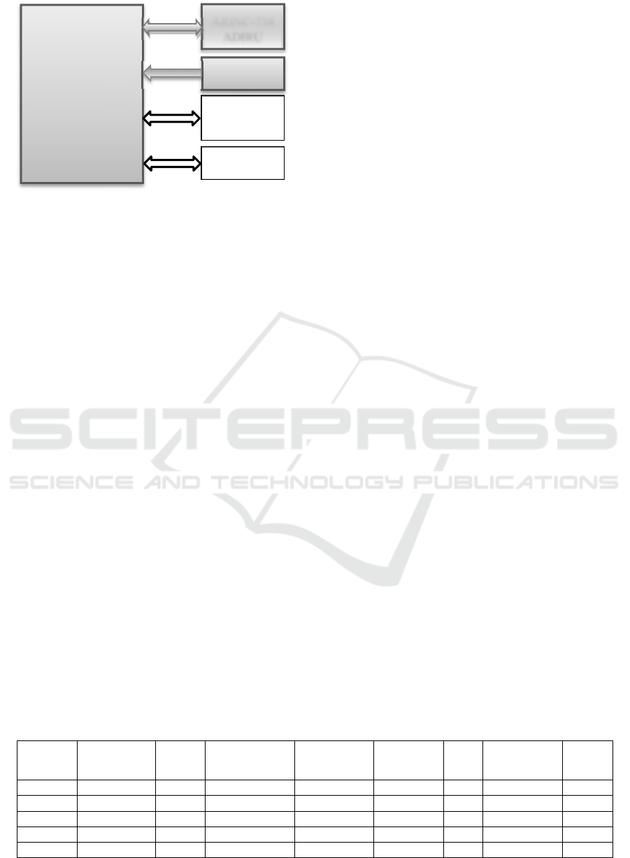
Figure 2: FMC connections.
4 DATA EXTRACTION PROCESS
In this Section, we present our proposed data
extraction process, its illustration and validation using
avionics system examples.
4.1 Main Sources of Information
To collect the system interfaces information, we
mainly use the ARINC-429 standard, and equipment
associated ARINC specifications, such as the
ARINC-7xx series of specifications to handle
federated systems as well as communications in both
IMA and federated architecture, and DO-297 and
DO-255 to handle IMA architecture.
4.1.1 ARINC-429
ARINC-429 (P1 and P2) represents an important
source of information about equipment data flows.
The ARINC-429 basic pieces of information are 32
bits digital words. A word content is identified by
three octal characters coded in binary and represents
the first eight bits of the word (word label).
The label code assignments are shown in
Attachment 1-1 to ARINC-429 (P1) (AEEC, 2012)
where the last three characters designate the
equipment identifier, and the equipment codes are
specified in Attachment 1-2 of this specification.
Depending on the type of encoding used (i.e.,
BCD or BNR), the characteristics of the words, such
as unit, range, and resolution to be transferred by the
ARINC-429 bus are specified in Attachment 2a and
Attachment 2b of this specification.
4.1.2 ARINC-7xx
In this work, we use the ARINC-7xx series of
specifications for both federated and IMA
architectures. In the federated context, the whole
interface specification of the associated equipment
can be extracted from its associated ARINC
specification. However, only connections and data
inputs/outputs can be specified for IMA applications
because they do not present physical interfaces. The
inputs/outputs are ARINC-429 words even in an IMA
architecture.
4.1.3 DO-297/DO-255
DO-297 (RTCA, 2005) and DO-255 (RTCA, 2000)
are used to specify IMA applications needs and
platform capabilities.
4.2 Process Illustration
The reader should be aware that this section and the
next ones illustrate the complex and highly iterative
nature of the underlying task (e.g., extracting ICD-
relevant information from a set of standards), which
is reflected in the proposed process. We have
attempted to be as clear as possible.
The three gray equipment of Figure 2, specified
in ARINC-702A, ARINC-738, and ARINC-710, are
used to illustrate the data extraction process depicted
in Figure 3 as a flowchart diagram. We refer to its
processes, numbered in bold face in Figure 3, in the
text below when illustrating the extraction process.
The processes and their data outputs having thick
borders are used to refer to software aspects of the
interfaces.
The FMS and ADIRU are used as IMA
Table 1: FMC to ADIRU (IR Portion) inputs (AEEC, 2001).
(OCTAL)
P
arameter name Signal
format
Max Transmit
interval (msec)
Range
(Scale)
SIG
Bits/Figures
PAD
FIG
UNITS RESOL
041 Set Latitude BCD 500 90S-90N 5 0 Deg/Min 0.1
042 Set Longitude BCD 500 180E-180W 6 0 Deg/Min 0.1
043 Set Magnetic BCD 500 0-359.9 3 2 Deg 0.1
150 UTC BNR 1000 23:59:59 17 N/A HR:MIN:SEC 0.1
260 Date BCD 1000 N/A 6 N/A D:M:YR 1 Day
ARINC-702
FMC
ARINC-738
ADIRU
ARINC-710
ILS
ARINC-739A
MCDU
ARINC-701
FCCU
A Data Extraction Process for Avionics Systems’ Interface Specifications
547
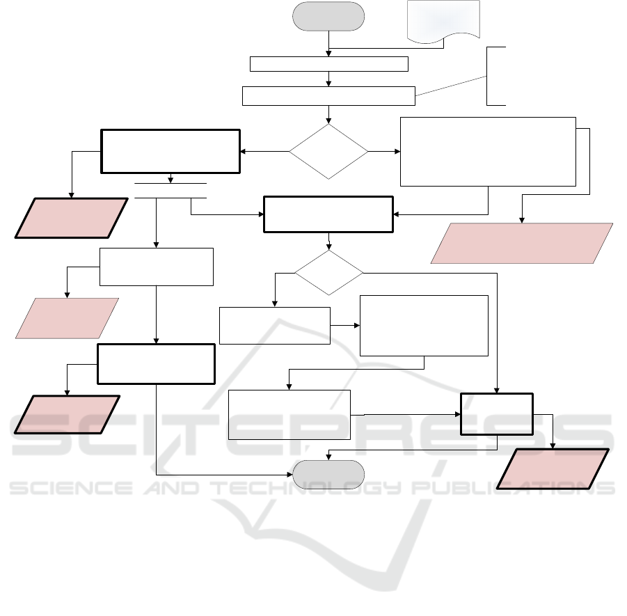
Figure 3: Flowchart of our proposed data extraction process.
applications and the ILS as a federated equipment.
Subsequently, we use the FMS and ADIRU ARINC
specifications to specify the inputs/outputs data as
well as their characteristics.
We start with the ADIRU ARINC-738A-1. The
first step as depicted in Figure 3 consists in consulting
the standard interwiring presented in one of the
ARNIC-738A specification Attachments
(Attachment 4-1 in our case). As the ADIRU is used
in an IMA architecture, we thus execute process (3)
and build the connection schema without taking the
number of ports and the electrical characteristics into
account (because IMA applications have no physical
interface).
Figure 2 depicts the ADIRU interconnection with
the other elements of our example. As stated earlier,
the gray parts will be used to illustrate the data
extraction process. Later on, both processes (4) and
(9) should be executed. Let us first start with the
process (4) which consists in checking the
specification attachments to verify if the set of
inputs/outputs are specified. In the Attachment 7-1 to
the ARINC-738A, the inputs/outputs of the Inertial
Reference (IR) function of the ADIRU are specified
and those of Air Data Reference (ADR) are specified
in its Attachment 7-2. To identify the sources of the
inputs and destinations of the outputs, we should
check the attachments again or the specification text
if any. In our case, the FMC input data are specified
in the text of page 14 of the same ADIRU
specification.
“The FMC provides Set Latitude (label 041), Set
Longitude (label 042), Set Heading (label 043), Time
(label 150) and Date (label 260) initialization data to
the ADIRU.”
Their characteristics are specified in Attachment
7-1 as shown in Table 1. However, the ADIRU
outputs to the FMC are not specified even in its old
versions when executing process (5). Hence, process
(6) consisting in the consultation of the corresponding
ARINC specification (and its old
Consult standard interwiring
Is it
federated?
Begin
ARINC-DOCs
DO-255/297
1) Build the connection schema with the
same number of pins as stated in the
standard
2) Extract electrical characteristics and
requirements using notes associated to
pins
Build the connection schema
regardless the number of pins
and electrical characteristics
Verify the equipment connections
Look for Inputs/Outputs data
in the same ARINC for each
interface
Are they
specified?
Check old versions of this
specification as well as
ARIC-429 P1
Produce the set
of inputs/
outputs data
Consult the corresponding
(transmitter/receiver)
Specification (and its old
version if needed) to extract
the exchanged parameters
Go to the data standard in
ARINC-429 and extract
these parameter
characteristics
Use the RTCA/DO-255 to
extract the platform
performance attributes
Use the RTCA/DO-255/297
to extract the hosted
applications attributes
Platform
capabilities
and limits
Set of inputs/
outputs data
- Connection schema
- Electrical characteristics
End
Connection
schema
Application
requirements
YesNo
Yes
No
(1)
(2)
(3)
(4)
(9)
(5)
(6)
(7)
(8)
(10)
If an output port is defined
as a general output port,
the corresponding
equipment specification
should be consulted
MODELSWARD 2016 - 4th International Conference on Model-Driven Engineering and Software Development
548
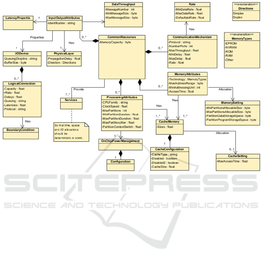
Figure 4: Conceptualization of the platform capabilities and limits.
versions if any) should be executed. After carefully
checking ARINC-702A, we found that the required
information is not specified. Hence, we consulted its
old version ARINC-702-6. We found that the set of
transmitted parameters along with their destinations
are specified in Attachment 4. The word labels can be
found using the FMC code “Eqpt Id=002” as well as
parameter names in Attachment 1-1 to the ARINC-
429-P1 by executing process (7). Furthermore, their
respective characteristics can be extracted in ARINC-
429 using the equipment codes along with words
labels.
The labels from the IR part of the ADIRU are:
BNR-encoded (212, 310, 311, 312, 313, 314, 317,
320, 321, 322, 323, 324, 325, 362, 363 and 364),
BCD-encoded (010, 011, 012, 013, 014 and 044), and
270 as a discrete output.
The labels from the ADR part of the ADIRU are:
BNR-encoded (204, 205, 206, 207, 210, 211, 213,
220, 251 and 252), and 270, 271, 350 and 351 as
discrete outputs.
Finally, the set of inputs/outputs can be produced
by executing process (8). The execution of process (9)
along with process (10) provides us with the set of the
platform performance attributes (see Figure 4) and the
set of application resource needs, respectively.
Let us now apply the process on the FMC
(ARINC-702A). Starting by process (1) of Figure 3
and based upon the “standard interwiring” page 100
of ARINC-702A, we built the FMC interconnection
diagram by executing process (3). As depicted in gray
in Figure 2, the FMC interacts with the ADIRU
(ARINC-739a-1) and ILS (ARINC-710-10).
Then, and similarly to the ADIRU and being
considered in an IMA context, both processes (4) and
(9) should be executed (see Section 2.2 of this paper
for processes (9) and (10)). Therefore, by checking
the ARINC-702 attachments as stated in process (4),
we found that only FMC outputs are specified in
Attachment 4. The only outputs we have for this
example are those sent to the ADIRU.
However, the ADIRU is not mentioned in the set
of FMC outputs destinations. Hence, the general data
output specified in the text of the specification is
consulted and we found that the ADIRU receives
initialisation data from the FMC. In Section 4.2.1of
the ARINC-702A, we found that these data are BCD-
encoded set latitude, set longitude, and set heading
along with date and time. The corresponding labels
(041, 042 and 043 in BCD-encoded) along with the
BNR-encoded (150 and 260) labels are found in
Attachment 4. Their respective characteristics can
A Data Extraction Process for Avionics Systems’ Interface Specifications
549
then be extracted from the ARINC-429 specification
using labels and FMC code.
As the set of inputs are not specified in that
version of FMC ARINC specification, we then
consulted (as stated in process (5)) its old version,
namely ARINC-702-6, and found this latter stated in
Attachment 4 as a set of received parameters. As the
old specification versions are used only for guidance,
the process (6) is then executed by consulting the ILS
and ADIRU specifications. As stated earlier, the
corresponding labels as well as the words
characteristics can be extracted from ARINC-429
using the source equipment code along with the
parameters names. Equipment codes in our case are
010 for the ILS and 038 for the ADIRU. The BNR-
encoded (010, 011, 012, 013, 014 and, 044 labels)
parameters, BCD-encoded (212, 310, 311, 312, 313,
314, 317, 320, 321, 322, 323, 324, 325, 362, 363 and,
364 labels) parameters as well as discrete (label 270)
parameter are received from the ADIRU. And the
BCD-encoded (label 33) parameter along with BNR-
encoded (173 and 174 labels) parameters are received
from the ILS. Hence, we can move to the process
number (8) to produce the set of inputs/outputs data.
By applying the process depicted in Figure 3, we
have first consulted the standard interwiring and as an
utilisation device port was defined, we consulted
those of ADIRU and FMC to verify if it interacts with
them. We have found that the FMC has an input data
port from the ILS but it is not the case for the ADIRU.
We therefore traced the interconnection diagram of
the ILS, shown in Figure 2, by executing process (2)
as the ILS is used in a federated context.
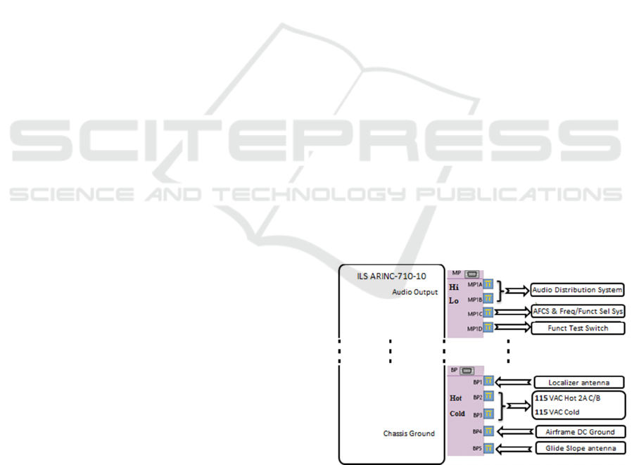
The physical interconnection diagram of the ILS
is depicted in Figure 5 along with its electrical
characteristics which can be extracted using notes
associated to the ILS pins and ports (e.g., the type of
wire, impedance, etc.).
We move to process (4) and according to the text
of Section 3.4 of the ARINC-710-10, we have found
two identical ILS receiver output ports: one serving
the Automatic Flight Control System (AFCS) and the
second dedicated for other utilisation devices (e.g.,
FMC). The data transmitted over these ports are the
localizer and glide slope deviation information that
are respectively identified by the labels 173 and 174,
as well as the ILS channel frequency that contains the
033 label code. The data standard is specified in
Attachment 3 but as this specification is old, we must
verify its compliance with the ARNIC-429
specification and extract the information from this
latter. We finally execute the process number (8) to
produce the set of inputs/outputs (in our case, we
consider only the interaction between gray equipment
specified in Figure 2).
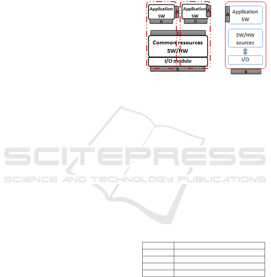
4.3 Summary
The data extraction process presented in this paper
allowed us to capture the information we consider is
required to be presented in an ICD.
A summary of relevant avionics system interfaces
is depicted in Figure 6. The right hand side of the
figure represents a federated equipment interfaces
while the left hand side represents the IMA system
interfaces. As stated earlier, interfaces of a federated
equipment refers to documentation of its interwiring
and data flow. Thus, the interfaces of a federated
equipment can be captured by logical interfaces “A”
on the figure, and physical interfaces “B” on the
figure. An interface type “A” captures the exchanged
data while an interface type “B” captures the
electrical characteristics of the interface (e.g.,
connectors, pins, voltage, impedance, etc.). An IMA
system is composed of several virtual systems
representing the different applications hosted on
shared common resources which provide spatial and
temporal isolation.
An IMA hosted application presents two types of
interfaces as shown in the left hand side of Figure 6.
An interface type A which captures the data
exchanged by the application, and an interface type
“D” specifying the application resource needs.
The common resources, as shown on the left hand
side of Figure 6, present an interface type “B”
describing its electrical characteristics and
interwiring as well as interface type “C” describing
its capabilities and limits.
Figure 5: ILS electrical characteristics.
An interface type “A” captures the set of data
inputs/outputs of applications, their characteristics
and formats. Table 1 shows an example of an
interface type “A” content which captures the FMC
MODELSWARD 2016 - 4th International Conference on Model-Driven Engineering and Software Development
550
outputs to the ADIRU, along with their
characteristics.
Figure 5 is an example of a federated equipment
interfaces type “B”. The DO-255 (RTCA, 2000,
tables 1-5) tables describe the attributes that should
be specified to describe an interfaces type “C” of the
common resources. An interface type “D” describing
application resources needs and requirements can be
captured using the attributes defined in (RTCA, 2000,
tables 1-5) in the form of assumes/guarantees
assumptions.
5 VA L I D AT I O N
In this paper, we used the FMC along with the gray
elements of Figure 2 to design and illustrate our
proposed data extraction process while the FMC and
the rest of elements are used in the validation process.
We used the ILS and MCDU in a federated
context and the rest of the elements in an IMA
context. To validate our proposed process, we applied
it on the FMC ARINC-702A, FCC ARINC-701and
MCDU ARINC-739A.
We first start by the FMC-ARINC-702A. We
consulted Attachment 2-2 and execute process (1).
However, a general output port, having the FCC as
one of its destinations (see Section 5.2.2 of ARINC-
702A), is defined and so should be considered. As the
FMC is considered in an IMA context, we execute the
process (3) to build the interconnection diagram
between the FMC and other equipment (depicted in
Figure 2 as non gray equipment and connections).
Then, we executed the process (4) to look for
inputs/outputs of the FMC to/from the FCC and
MCDU. The general (optional and basic) data outputs
are specified in Attachment 4 of ARINC-702A of the
FMC specification and their characteristics can be
extracted from ARINC-429 using their labels as well
as the FMC code equipment (002). However, the data
inputs are not specified, thus we move to the process
(5) to consult its old version ARINC-702-6.
In Attachment 4 of ARINC-702-6, the inputs
(selected course, selected heading, selected altitude,
selected airspeed, selected vertical speed, and
selected mach) from the FCC (Glare Shield
Controller) are specified. Using the equipment code
(0A1) and parameters names, we found the following
FCC inputs in ARINC-429: BCD-encoded (020, 022,
023, 024, 025, 026, and 027 labels) parameters along
with BNR-encoded (100, 101, 102, 103, 104, 105,
106, and 110 labels) parameters. Subsequently, we
execute the process (6) and consult the FCC
specification to check the set of outputs from the FCC
to the FMC. In page 16, the BNR-encoded (100, 110,
102, 103, 101, 106, 104, 105, and 112 labels) and
BCD-encoded (024, 027, 025, 026, 023, 022, 020,
017, and 021 labels) are specified.
Figure 6: Avionics systems interfaces.
The outputs of the FMC to the MCDU, which is
considered in a federated context, are partially
specified in Attachment 4 of the FMC specification.
These outputs are (220, 221, and 222) address labels
as well as 250 BNR-encoded label. It is mentioned
that we should consult ARINC-739 for other outputs
to the MCDU. By executing process (6), we consulted
ARINC-739A and found, in section 3.9.7, the words
along with their labels specified. The inputs from the
MCDU to the FMC are not specified even in the old
version of the FMC specification, so process (6) is
executed. Therefore, the ARINC-739A is consulted
and the outputs to the FMC are specified in its section
3.2. Inputs and outputs can be extracted from the
ARINC-429 by executing process (7) and using the
MCDU code (039) and the word labels (377 of the
MCDU identification, 270 discrete word, and 350
maintenance word). We finally execute process (8) to
produce the set of data inputs/outputs of the FMC.
Table 2: Summary of interface content examples.
Inte
r
faces Examples
ATable 1
BFi
g
ure 5 and Fi
g
ure 7
CFi
g
ure 4
D DO/255 (RTCA, 2000, tables 1-5)
We apply our proposed process starting by the
process (1) on a second equipment (FCC ARINC-701),
which is considered in an IMA context. The
communication diagram is then built by executing
process (3) (see Figure 2, connection between FMC
and FCC). Furthermore, we looked for inputs/outputs
by executing process (4), (see Section 2.2 of this paper
for process (9) and (10)). The outputs to the FMC
labels are specified in page 16 and are BNR-encoded
A Data Extraction Process for Avionics Systems’ Interface Specifications
551
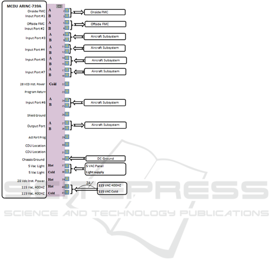
Figure 7: MCDU electrical characteristics.
(100, 110, 102, 103, 101, 106, 104, 105, and 112
labels) and BCD-encoded (024, 027, 025, 026, 023,
022, 020, 017, and 021 labels). Their characteristics
can be extracted from ARINC-429 using the FCC
controller code equipment (0A1) as well as those
labels. The inputs from the FMC are specified in
Attachment 6 of ARINC-701 but associated with the
mention TBD, which means that the FMC inputs are
not specified yet. As there is no old version of this
specification, we move from process (5) to (6)
directly and thus consult the corresponding
specification (ARINC-702A). In its Attachment 4, the
general outputs are specified and in Section 5.2.2, it
is stated that the FCC receives the FMC general data
outputs. These inputs to FCC can be extracted from
ARINC-429 using FMC code equipment along with
the outputs labels by executing process (7). Finally,
we produce the set of FCC inputs/outputs through the
execution of process (8).
We then applied our data extraction process on
the MCDU ARINC-739A, which is considered as a
federated equipment. We consulted the standard
interwiring in the Attachment 1 and executed process
(1) to verify its connections. As it presents
connections to aircraft subsystem without specifying
them, the corresponding specifications of our
validation equipment are consulted. Hence, we
concluded that the FCC has no connection to the
MCDU. Then, we produced the MCDU
interconnection diagram considering the same
number of ports by executing process (2) as shown in
Figure 7. We then executed process (3) to look for the
MCDU inputs/outputs. As the MCDU communicates
with the FMC and as stated in Section 3.5 of the
MCDU specification, the outputs of the MCDU are
provided by a single output port and should include
its identification (337 label), discrete (270 label), and
maintenance word (350 label). Inputs to the MCDU
from the FMC are specified in Section 3.9.7 of the
ARINC-739A and can be extracted from ARINC-429
using the FMC code and the parameters labels. We
then executed the process (8) to produce the set of
inputs/outputs to/from the MCDU. The MCDU
communication protocol is defined in Section 3.7 of
ARINC-739A and the word formats are specified in
its Attachment 3.
The interfaces that an avionics system can present
are described in
Figure 6 and their related contents, captured using
the proposed data extraction process, can be
summarised in Table 22.
6 RELATED WORKS
The concept of interface has different meanings in the
literature. Thus, the tools needed for defining and
managing them are also different, depending on the
different perceptions of what an interface is.
In fact, a recent systematic literature review
(Parslov, and Mortensen, 2015) on interface
definitions has shown that there are thirteen different
definitions (perceptions) of an interface in the
literature. In addition, it has been found that around
half of these perceptions consider an interface as part
of the elements, instead of being a separate design
object. Considering an interface as part of elements,
which enables compatibly checks and independent
element tests, is suitable for an integration process
and bottom-up approach. Thus, depending on
whether an interface is considered as part of elements
or not, and depending on its definition and content,
the existing solutions of interface modeling can be
useful or not for us in the context of this research
project.
Despite the important role of ICDs in the process
of building avionics systems, only a few recent
MODELSWARD 2016 - 4th International Conference on Model-Driven Engineering and Software Development
552

research works have addressed the problems of their
ambiguous definitions and challenges of their use
when building avionics systems using their ICDs
(Louadah, Champagne and Labiche, 2014).
Among these works, Rahmani and Thomson have
proposed a systematic methodology for modeling
interfaces (Rahmani, and Thomson, 2011). They have
reused the principle of interfaces categorization and
hierarchization to provide a unique interface
architecture topology for two interacting subsystems.
Thus, they defined a generic model for ICDs based on
class diagrams but considered an interface as the type
of objects and media that flow through sub-system
ports.
Another work of the same authors proposed a
computer aided methodology for defining and
controlling subsystem interfaces (Rahmani and
Thomson, 2012), enabling a formal expression of
interface requirements and mating rules of two
subsystems (which can be useful for physical
interfaces compatibility checking). However, the
interface is considered as a connection between two
ports, and thus, could exist only by having knowledge
about the two ends of such a connection and restricted
to hardware systems interfaces. However, in avionic
systems, we need to specify both hardware and
software interfaces.
Pajares et al. proposed a tool for ICD
Management for embedded avionic systems (Pajares
et al., 2010). They defined a set of meta-models (data
definition, data coding and communication
architecture) for defining and managing ICDs in a
formal way, capturing only a subset of the
information that one typically requires in an ICD. In
a similar way, Tapp defined a language to describe
system interfaces related to the various aspects
surrounding their data exchanges (Tapp, 2013),
though without mechanisms to specify constraints on
the interfaces. Luca de Alfaro et al. on the other hand,
focused only on constraints, defining sets of
assumptions and guarantees on an interface’s inputs
and outputs variables respectively (de-Alfaro, and
Henzinger, 2005). In fact, the authors proposed a
stateless interface language dubbed assume/guarantee
and particularly, the notion of interfaces
composability, formally verifiable, to check the
interfaces compatibility of two components designed
separately.
Other works such as (Specht, 2009 ; L-Sergent
and Guennec, 2014) advocate the use of some tools
but don’t bring significant help to integrators using
ICDs when building avionic systems. In fact, the use
of these tools helps to better manage ICDs contents,
but can’t bring any help to the unsystematic and
ambiguous description of interfaces.
Sabetzadeh et al., proposed a methodology for
modeling SW/HW interfaces using SysML (Systems
Modeling Language), but they considered an
interface as a separate design object which is more
suitable for top-down approach (Sabetzadeh et al.,
2011).
Other works such as (Specht, 2009 ; L-Sergent
and Guennec, 2014) advocate the use of some tools
but don’t bring significant help to the integrators
using ICDs when building avionic system. In fact, the
use of these tools offers better management of ICDs
contents but can’t bring any help to the unsystematic
and ambiguous description of interfaces.
Sabetzadeh et al., proposed a methodology for
modeling SW/HW interfaces using SysML (Systems
Modeling Language), but they consider an interface
as a separate design object which is more suitable for
top-down approach (Sabetzadeh et al., 2011). Fosse
and Delp proposed a model-based approach for
modeling interfaces and interactions based on SysML
(Fosse and Delp, 2013). The authors have decoupled
the inputs/outputs and their related constraints from
the interface specification to be considered as part of
system interaction specification. However, for
integration concerns, the compatibility between the
sender/receiver set of inputs/outputs should be
verified.
In summary, none of the existing works has
covered the interface concepts needed in the context
of avionic systems integration. As stated earlier, the
first step toward developing a solution that will meet
the avionic integration needs, which is the main aim
of this paper, is the identification of what an ICD
should contain.
7 CONCLUSIONS
AND PERSPECTIVES
In this paper, we introduced a data extraction process
aiming to reduce the effort and time needed to
understand, read and extract avionics system
interfaces data from open avionics standards.
We illustrated and validated our data extraction
process using a flight management system and some
of other systems interfacing with it namely FCC,
MCDU, ADIRU, and ILS.
This paper provides a clear vision on what an
interface specification should include in both
federated and IMA avionics systems and thus
represents a step towards designing a complete
model-driven solution for modelling avionics system
interfaces.
A Data Extraction Process for Avionics Systems’ Interface Specifications
553

Future work will investigate the usefulness and
efficiency of this process and subsequently focus on
proposing an ICD modelling solution based on the
results of this work.
ACKNOWLEDGEMENTS
This work has been financed by NSERC/CRIAQ
project AVIO-506 in collaboration with our industrial
partners CMC Electronics and Solutions Isonéo.
REFERENCES
Watkins, C.B., Walter, R., 2007. Transitioning from
federated avionics architectures to integrated modular
avionics. In DASC '07, 26th Digital Avionics Systems
Conference. IEEE/AIAA.
Watkins, C.B., 2006a. Integrated Modular Avionics:
Managing the Allocation of Shared Intersystem
Resources. In DASC '06, 25th Digital Avionics Systems
Conference. IEEE/AIAA.
Cook, A., Hunt, K.J.R., 1997, ARINC 653 — Achieving
software re-use, Microprocessors and Microsystems,
Volume 20, Issue 8, Pages 479-483, ISSN 0141-9331,
http://dx.doi.org/10.1016/S0141-9331(97)01113-7.K.
Watkins, C.B., Walter, R., 2008. Design considerations for
systems hosted on Integrated Modular Avionics
platforms. In DASC '08, 27th Digital Avionics Systems
Conference. IEEE/AIAA.
AEEC., 2009a. ARINC-664-P7: Aircraft data network part
7 avionics full-duplex switched Ethernet network.
Aeronautical Radio.
AEEC., 1998. ARINC-739A-1: Multi-purpose Control and
Display Unit. Aeronautical Radio.
AEEC., 1994. ARINC-702-6: Flight Management
Computer System. Aeronautical Radio.
AEEC., 1997a. ARINC-651: Design Guidance for
Integrated Modular Avionics. Aeronautical Radio.
Moir, I., Seabridge, A., Jukes, M., 2013. Civil avionics
systems.Wiley, 2nd Edition.
RTCA Inc., 2000. RTCA/DO-297: Requirements
specification for Avionics Computer Resource (ACR),
SC-200.
RTCA Inc., 2005. RTCA/DO-297: Integrated Modular
Avionics (IMA) Development Guidance and
Certification Considerations, SC-200.
AEEC., 1983. ARINC-701-1: Flight Control Computer
System. Aeronautical Radio.
AEEC., 2001. ARINC-738A-1: Air Data and Inertial
Reference System. Aeronautical Radio.
AEEC., 1997b. ARINC-710-10: MARK 2 airborne ILS
receiver. Aeronautical Radio.
AEEC., 2006. ARINC-702-A3: Advanced Flight
Management Computer System. Aeronautical Radio.
AEEC., 2010. ARINC 653: Avionics Application software
standard interface. Aeronautical Radio.
AEEC., 2012. ARINC 429P1-18: Digital Information
Transfer System (DITS) part 1 functional description,
electrical interfaces, label assignments and word
formats. Aeronautical Radio.
Spitzer, C.R., Ferrell, U., Ferrell, T., 2014. Digital Avionics
Handbook, CRC Press, 3rd Edition.
Louadah, H., Champagne, R., Labiche, Y., 2014. Towards
Automating Interface Control Documents Elaboration
and Management. In International Workshop on
Model-Based Architecting and Construction of
Embedded Systems, satellite event to Models 2014.
Watkins, C.B., 2006b. Modular Verification: Testing a
Subset of Integrated Modular Avionics in Isolation. In
DASC '06, 25th Digital Avionics Systems Conference.
IEEE/AIAA.
Parslov, J.F., Mortensen, N.H., 2015. Interface definitions
in literature: A reality check. Concurrent Engineering:
Research and Applications.
Rahmani, K., Thomson, V., 2011. Managing subsystem
interfaces of complex products. International Journal
of Product Lifecycle Management.
Rahmani, K., Thomson, V., 2012. Ontology based interface
design and control1 methodology for collaborative
product development. CAD Computer Aided Design.
Pajares, M., ngel, M., Daz, C.M., Pastor, I.L., Hoz, C.F.,
2010. ICD Management (ICDM) tool for embedded
systems on aircrafts. ERTS2.
Tapp, M., 2013. Automating system-level data-interchange
software through a system interface description
language. École polytechnique de Montréal.
de-Alfaro, L., Henzinger, T.A., 2005. Interface-based
Design. Engineering Theories of Software Intensive
Systems. Springer-Verlag.
Specht, M., 2009. Creating, maintaining, and publishing an
interface control document (ICD). AHS Technical
Specialists Meeting on Systems Engineering.
L.Sergent, T., L.Guennec, A., 2014. Data-Based System
Engineering: ICDs management with SysML. ERTS2.
Sabetzadeh, M., Nejati, S., Briand, L., Evensen-Mills A.H.,
2011. Using SysML for Modeling of Safety-Critical
Software-Hardware Interfaces: Guidelines and Industry
Experience, IEEE/HASE.
Fosse, E., Delp, C., 2013. Systems engineering interfaces:
A model based approach, IEEE Aerospace Conference
Proceedings.
MODELSWARD 2016 - 4th International Conference on Model-Driven Engineering and Software Development
554
