
Imaging Characteristics of the Axicon Imaging System
Zhongsheng Zhai
1
, Qinghua Lv
2, 3
, Xuanze Wang
1
, Liangen Yang
1
, Zhongbao Xu
1
and He Tao
1
1
School of Mechanics and Engineering, Hubei University of Technology, Lizhi Road, Wuhan, Hubei, China
2
Hubei Collaborative Innovation Center for High-efficient Utilization of Solar Energy,
Hubei University of Technology, Lizhi Road, Wuhan, Hubei, China
3
School of Science, Hubei University of Technology, Lizhi Road, Wuhan, Hubei, China
Keywords: Depth of Field, Non-diffracting Beams, Axicon, Imaging Characteristics.
Abstract: The depth of an image system can be extended by an axicon which can generate line focus. According to
physical optical theory, the diffracting patterns of the defocus point spread function (PSF) for the imaging
system with axicon are analyzed through the generalize pupil function. The expressions of the PSF for the
imaging system illuminated by white light are described as the superposition of the intensities in individual
monochromatic patterns. Experimental results show that the central portion contains the most energy of the
diffraction pattern from the PSF produced by the white light, and the contrast of secondary outside circular
rings decreased rapidly. Furthermore,the central spot radius varied slowly with the increase of defocus
parameter, and the depth of field of the imaging system is effectively extended with a shortcoming that the
images need further processing.
1 INTRODUCTION
In 1987, the team of J. Durnin found the solution of
the Maxwell's wave equation, which was given as
zero-order Bessel function forms, and first put
forward the concept of nondiffracting beams (Durnin,
1987). Nondiffracting beams which has
characteristics that the size of central spot and shape
does not change significantly over a propagation
distance. In 1992, G. Scott and other researchers used
the axicon to generate nondiffracting beams (Scott
and McArdie, 1992).
The ‘axicon’, first introduced by McLeod in 1954,
can form an extended focal segment which has the
zero-order Bessel distribution, and it can also
generate annular beams in the far region. (McLeod,
1954). Axicons have been incorporated in numerous
applications. Zhai using the axicon, simulated by a
spatial light modulator to to improved the efficiency
of laser processing (Zhai and Kuang, 2014).
Guillaume Druart demonstrated the diffractive axcion
has image-zooming capability, and they realized a x2
linear system (Druart et al., 2008). Zeng et al. used a
refractive axicon to transform an input Gaussian laser
beam into a collimated annular beam, which refer to
as optical trepanning. (Zeng et al., 2006).
In recent years the ability of annular linear axicons
for extending the depth of field of imaging system has
proposed by some researchers (Mikula et al., 2005).
They fixed the distance between the input object and
the diffractive elements, and obtained output images
in different output planes behind the axicon. In an
early publication (Zhai and Zhao, 2007), we have
derived the diffraction patterns of an axicon
illuminated by a red high brightness LED, and the
patterns were looked as the PSFs of the axicon
imaging system. However, the expressions of the
PSFs were calculated by the point light source in
different positions,not by the defocus aberration.
The aim of this paper is to analyze the imaging
principle of axicon, and to analyze the relationship
between the PSF and the defocus parameter. Imaging
results proved that the axicon can extend the depth of
field. The images created by this system can be
observed in real time, but they exhibit a very poor
contrast. For getting clearer images, digital
processing method is required.
Zhai, Z., Lv, Q., Wang, X., Yang, L., Xu, Z. and Tao, H.
Imaging Characteristics of the Axicon Imaging System.
DOI: 10.5220/0005742201350139
In Proceedings of the 4th International Conference on Photonics, Optics and Laser Technology (PHOTOPTICS 2016), pages 137-141
ISBN: 978-989-758-174-8
Copyright
c
2016 by SCITEPRESS – Science and Technology Publications, Lda. All rights reserved
137
2 THEORIES
2.1 Defocus Aberration
It is well known that defocus aberration manifests
itself by a quadratic phase at the imaging system
pupil, i.e.
)](exp[),,(
22
vuivuG +=
ϕϕ
(1)
where (u, v) are the normalized coordinates of the
pupil plane, and the defocus parameter φ is defined
by the following expression (Eliezer et al., 2008):
)
111
(
2
'
2
20
fl
l
d
W −−==
λ
π
λ
π
ϕ
(2)
where W
20
is Hopkins defocus factor, d is the pupil
radius, λ is the wavelength, f, l and l’ are the lens focal
length, the distances from the object and the image to
the lens respectively.
Obviously, when imaging condition is fulfilled:
0
111
'
=−−
fl
l
(3)
From equation 2, we can observe that the defocus
parameter φ equals zero. In the large DOF imaging
system, when a focus aberration occurs, as shown in
figure 1, the wavefront is deformed and it can use the
generalize pupil function to describe the defocus
error. The defocus factor is given as:
2
20
)
11
(
2
1
r
zz
W
la
⋅−=
(4)
where r is the radius of the pupil. z
l
is the distance
from the ideal image plane to the lens, and z
a
is the
distance between the lens and the defocus image
plane. In the common imaging system, the defocus
factor is changed with the increase of z
a
.
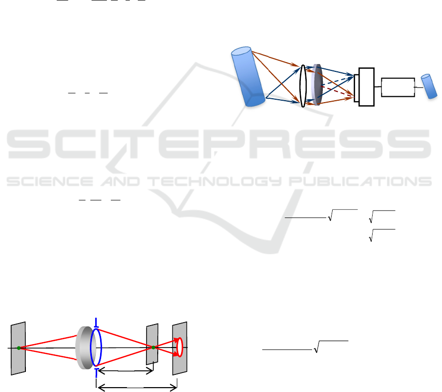
Figure 1: Scheme of defocus system.
2.2 Imaging System Design
An imaging system was arranged as shown in figure
2. It mainly includes a light source, battery of lens, an
axicon, a CCD detector and a computer. The axicon
is placed at the back of lens, and a CCD camera is
used to capture intermediate images when the object
moves within a specified region before the lens. The
object is illuminated with incoherent light. The
quality of the intermediate images is so poor that an
image processing portion is needed. For better
considering the depth of field, in the designed
imaging system, the distances between the lens,
axicon and CCD camera are fixed. It requires post-
processing steps in order to achieve a high quality
image, so it is a two step imaging system.
Figure 2: Schematic diagram of non- diffractive beam
imaging system.
2.3 PSF of Defocus
Consider a thin axicon with a transmittance function
given by
+
−−
=
0
2
)1(
exp
)(
22
vu
Dnik
rt
θ
1
1
22
22
>+
≤+
vu
vu
(5)
where u, v are the normalized pupil coordinates, n is
the refractive index, D is the diameter of the axicon,
k is the wave number 2π/λ, and θ is refracting angle.
After putting the axicon in the pupil of the
imaging system, when aberrations are introduced, the
generalized pupil function may be described as
)](exp[]
2
)1(
exp[
),,(),(),,(
2222
vuivu
Dnik
vuGvutvuQ
++
−−
=
=
ϕ
θ
ϕ
ϕ
(6)
where φ is the defocus parameter.
According to the theory of Fourier optics, in the
diffraction-limited imaging system, the point spread
function is the Fraunhofer diffraction pattern of pupil
function. Therefore, we can obtain the PSF of the
system with the axicon as:
Defocus
image
z
a
Objec
t
Pupil Image
Z
l
Compute
r
Axicon
CCD
Objec
t
Image
PHOTOPTICS 2016 - 4th International Conference on Photonics, Optics and Laser Technology
138

dudvyvxu
z
i
vuivu
Dnik
dud
v
yvxu
z
ivuQ
z
A
yxh
i
ii
]}[
2
exp{
](exp[]
2
)1(
exp[
]}[
2
exp{),,(),,(
2222
+−⋅
++
−−
=
+−=
λ
π
ϕ
θ
λ
π
ϕ
λ
ϕ
(7)
where A is the amplitude of the incident beam, Z
i
is
the distance from the axicon to the image plane.
The optical system is circular symmetry, and for
the sake of simplicity, we make a transformation to
polar coordinates in both the (u, v) and the (x, y)
planes as follows:
γργρ
γ
ρ
βρβρ
β
ρ
sin,cos
)arctan(
sin,cos
)arctan(
11
22
1
22
==
=
+=
==
=
+=
yx
x
y
yx
vu
u
v
vu
(8)
Applying the coordinate transforms, the PSF can
be written as
−−⋅
+
−−
=
π
βγβρρ
λ
π
ρϕρρ
θ
ρϕρ
2
0
1
2
1
)]cos(
2
exp[
]
2
)1(
exp[),(
d
z
i
di
Dnik
h
i
(9)
Taking into account the circular symmetry of the
second integral in Eq (9), we use the Bessel function
identity
)(2)]cos(exp[
0
2
0
aJdia
=−
π
πβγβ
(10)
where J
0
is a Bessel function of the first kind, zero
order. Substituting (10) in Eq.(9), we can obtain
ρϕρρ
θ
ρρ
λ
π
ρπϕρ
di
Dnik
z
Jh
i
]
2
)1(
exp[
)
2
(2),(
2
101
+
−−
⋅
=
(11)
With the stationary phase method (Goodman,
1996), Eq. (11) can be approximated by following:
]
2
)1(
exp[
)
2
(2),(
2
101
ss
s
i
s
i
Dnik
z
Jh
ϕρρ
θ
ρρ
λ
π
ρ
ϕ
π
πϕρ
+
−−
⋅
≈
(12)
where ρ
s
is the stationary point,
ϕ
θ
ρ
4
)1( Dnk
s
−
=
(13)
In an incoherent imaging system, the intensity of
point spread function can be given by
22
)},({),,(),,(
ϕρϕϕ
QFyxhyxh
I
==
(14)
For the sake of simplicity, 1-D analysis of Eq.(14)
is performed as:
)
)1(
(
4
)
2
(
4
),(
1
20
2
0
20
3
1
2
0
3
1I
ρ
θ
ρ
π
ρρ
λ
π
ρ
ϕ
π
ϕρ
Wz
Dnk
J
kW
z
Jh
i
s
s
i
s
−
=
≈
(15)
Note that Eq.(15) is the expression of the PSF of
the axicon imaging system under monochromatic
light. If the light source is polychromatic light or
white light, the PSFs for the these source are different
from Eq.(15). The white light can be represented by a
combination of mutually incoherent monochromatic
components extending over a range of frequencies.
Each component produces a diffraction pattern as
described above, and the total intensity is everywhere
the sum of the intensities in these monochromatic
patterns. If the wavelength bandwidth of the light
source is λ
∈
[λ
beg
, λ
end
], the PSF of imaging system
with axicon illuminated with white light can be
expressed as
λρ
θ
ρ
ϕ
π
ϕρ
λ
λ
d
Wz
Dnk
Jh
end
beg
i
s
−
= )
)1(
(
4
),(
1
20
2
0
3
1I
(16)
3 SIMULATION
AND EXPERIMENT
To demonstrate the above theoretical analysis, we have
carried out numerical simulations and experiments.
Numerical simulations for the PSFs at different
defocus aberration conditions φ =0.5π, π, 2π, 4π, were
done by use of Eq. (16), as shown in figure 3.
Imaging Characteristics of the Axicon Imaging System
139
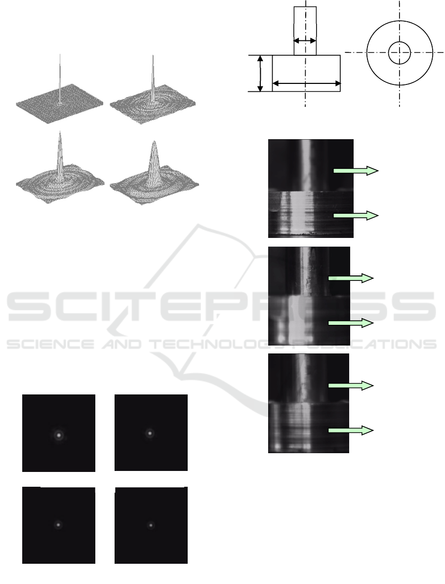
Some parameters were given by θ = 0.05, n =1.5,
z =120mm, f =120mm, D = 10mm and λ
∈
[380, 780]
nm. From figure 3, it follows that the central spot
radius varied with the change of defocus parameter φ.
Figure 3: Simulation of PSFs for different φ.
An experimental imaging system was constructed
based on figure 2, and some parameters of this
imaging system are the refractive index of the axicon
n = 1.5, the refracting angle of the axicon θ = 0.01rad.
Figure 4 gives the experiment result of the normalized
PSFs for the system under incoherent illumination in
case of l =160, 210, 260, 310mm. Obviously, the
central portion contains the most energy of the
diffraction pattern from the PSF produced by the
white light, and the contrast of secondary outside
circular rings decreased rapidly. Therefore, the
imaging characteristics of the system with the axicon
are mainly determined by the central spot.
Figure 4: Experiment results of the PSFs for different l. (a)
160mm, (b) 210mm, (c) 260mm, (d) 310mm.
Figure 5: Structural diagram of a candlestick.
Figure 6: Imaging results by the system (a) (b) without the
axicon, (c) with the axicon.
An imaging experiment for a candlestick with two
different diameter parts was exhibited using the same
system. Figure 5 presents the structure diagram. The
images in figure 6(a) and 6(b) were taken by the
standard imaging system without the axicon, and the
image in figure 6(c) was acquired in the case of the
system with the axicon. From figure 6(a) and 6(b), it
is obvious that only one part of the candlestick is clear
which is in the focus plane, and the other part is
blurring for the reason of defocus.
In figure 6(c), we also can observe that even the
φ =0.5π φ =π
φ =2π φ =4π
(a) (
b
)
(c) (
d
)
Φ12
10
Φ48
b
lured
b
lure
d
clear
clear
(a)
(b)
(c)
not clea
r
no
t
clear
PHOTOPTICS 2016 - 4th International Conference on Photonics, Optics and Laser Technology
140

images of the both parts of the candlestick are not as
clear as the images in focus plane, but they are more
clear than those in the out of focus place. Therefore
the image acquired by the imaging system with the
axicon is insensitive to defocus, and the depth of field
of the imaging system is effectively extended.
However, it has a shortcoming that the images have
low contrast and low resolution. The quality of the
intermediate images is so poor that an image
processing portion is needed.
4 CONCLUSIONS
We have investigated the imaging feature of the
axicon for extending depth of field. The diffraction
intensity distribution of PSFs of the imaging system
illuminated with monochromatic and white light are
clearly derived based on the generalize pupil
function. The experimental results proved that the
PSF for white light could be obtained by the
superposition of the intensities in individual
monochromatic patterns, and imaging results showed
that the axion can extend the depth of the field with
unclear images which need further processing.
ACKNOWLEDGEMENTS
This work was supported by the National Natural
Science Foundation of China (Nos. 51405143,
51575164, 5125157, 51275158), the Doctoral
Scientific Research Foundation of Hubei University
of Technology (No. BSQ13048) and Research
Foundation of Hubei Collaborative Innovation Center
for High-efficient Utilization of Solar Energy (No.
HBSKFZD2014007).
REFERENCES
J. Durnin, 1987. Exact solutions for Nondiffracting Beams,
Physical Review Letters. 58, 1479-1501 .
G. Scott, N. McArdie, 1992. Efficient generation of nearly
diffraction-free beams using an axicon. Optical
Engineering 31(12), 2640-2643.
H. J. Mcleod, 1954. The axicon: a new type of optical
element, J. Opt. Soc. Am. 44, 592-597.
Z. Zhai, Z. Kuang, et al. 2014. Synchronization control for
Ultrafast laser parallel microdrilling system SPIE 9271.
G. Druart, J. Taboury,et al, 2008. Demonstration of image-
zooming capability for diffractive axicons. Optics
Letter, 33, 366-368.
D. Zeng, W. P. Latham, A. Kar, 2006. Characteristic
analysis of a refractive axicon system for optical
trepanning, Optical Engineering. 45(9), 094302 .
G. Mikula, A. Kolodziejczyk, M, Makowski. 2005.
Diffractive elements for imaging with extended depth of
focus, Optical Engneering, 44, 058001-1-7.
Z. Zhai, B. Zhao, 2007. Diffraction Intensity distribution of
an axicon illuminated by polychromatic light. Journal
of Optics A: Pure and Applied Optics, 9(10): 862-867.
E. B. Eliezer, N. Konforti, et al, 2008. An optimal binary
amplitude-phase mask for hybrid imaging systems that
exhibit high resolution and extended depth of field.
Optics Express,16(25), 20540-61.
J. W. Goodman, 1996. Introduction to Fourier Optics,
McGraw-Hill, New York,.
Imaging Characteristics of the Axicon Imaging System
141
