
Data Link Layer Effect over Swarm Underwater Network
Performance
Samuela Persia
1
, Marco Tabacchiera
2
and Silvello Betti
2
1
Fondazione Ugo Bordoni, viale del Policlinico 147, 00161, Rome, Italy
2
Department of Electronics Engineering, University of Rome, “Tor Vergata”, Rome, Italy
Keywords: Acoustic Communication, Aloha Protocol, ARQ Protocol, Bit Error Rate, Data Link Layer, Frame Error
Probability, FSK Modulation, MAC Layer, Network Layer, OOK Modulation, Optical Communication.
Abstract: The Underwater Swarm is a particular Underwater Network configuration characterized by nodes very close
one to each other, with mobility capability. This type of network raises challenges for its effective design
and development, for which the only use of acoustic communication as traditionally suggested in
underwater communication could be not enough. A new emerging solution could be a hybrid solution that
combines the use of acoustic and optical channel in order to overcome the acoustic channel limitations in
underwater environment. In this work we want to investigate how the acoustic and optical communications
influence the Underwater Swarm performance by considering the Data Link Layer effects over the two
different propagation technologies. Performance simulations have been carried out to suggest how a new
Underwater Swarm based on hybrid communication technology could be designed.
1 INTRODUCTION
Underwater communications have experimented a
growing interest during the last years for different
application fields from oceanography to undersea
monitoring. Among different underwater networks,
the swarm appears to have more interesting
challenges for its effective design and development
due to the typical limitation of the underwater
environment, and the dependence of the topology
configurations. To respond to these open issues, a
new emerging solution could be a hybrid solution
that combines the use of acoustic and optical
channel, to take advantage by the two different
technologies: the acoustic communications are
characterized by low bandwidth and high power
consumption, but they can cover long distance and
are water condition independent; optical
communications are able to provide higher
bandwidth with lower energy consumption, but
suffer from highly limited communication range and
water conditions. Hence, the hybrid system could
use optical channel or acoustic one according to the
application (i.e. data rate required) and the
environment (i.e. water conditions). This permits to
have in the same device two alternative technologies
according to the underwater services needs. Several
research activities have been conducted in this
direction to evaluate the different communication
channels performance (Hon et al., 2014).
In this work, we are going to investigate how the
acoustic and optical communications can influence
the performance of the network. More deeply, we
investigate the lower protocol layers (Physical
Layer, Data Link Layer and Network Layer) effects
over the Underwater Swarm for the different
propagation technologies considered in order to
suggest how the new hybrid system could be
designed.
The article is organized as follows: a brief
introduction of the Swarm Network with the
corresponding lower layers challenges needed are
provided in Section II. The main results are
summarized in Section III, and finally in Section VI
the main conclusions are drawn.
2 UNDERWATER SWARM
An Underwater Swarm is characterized by a set of
AUV (Autonomous Underwater Vehicles) devices,
i.e. nodes of the network, very close one to each
Persia, S., Tabacchiera, M. and Betti, S.
Data Link Layer Effect over Swarm Underwater Network Performance.
DOI: 10.5220/0005730901210128
In Proceedings of the 5th International Confererence on Sensor Networks (SENSORNETS 2016), pages 121-128
ISBN: 978-989-758-169-4
Copyright
c
2016 by SCITEPRESS – Science and Technology Publications, Lda. All rights reserved
121

other, with mobility capability. The structure of the
network is that of a distributed network, in which the
nodes, through the exchange of control information,
will take decisions in collaborative manner. The
applications and the corresponding performance are
strictly related to the swarm configurations. In
particular:
Alarm Detection (Pipeline Configuration): the
swarm detects an alarm occurrence, for instance
a measured value of a specific parameter (e.g.,
oil in the water) is higher than a given threshold,
and thus, it will be ready to coordinate itself and
move towards the area, in which the anomalies
have been detected. From a communication point
of view, it means that each node is connected
only to one next node and all the nodes are
allocated in a linear manner. In this case a heavy
data transmission is assumed in a directional
way.
Data Processing and Report (Dense Swarm
Configuration): the swarm needs to acquire and
process complex data such as image, and thus, it
will be ready to coordinate itself and move very
close each to other towards the area, in which the
anomalies need to be relevated. From a
communication point of view, it means that each
node is connected only to its closest neighbours
and to forward information towards the
collecting node (i.e. the sink node), a multi-hop
paradigm is needed.
Periodical Monitoring (Swarm Configuration):
nodes perform periodical measurements of
proper parameters. From a communication point
of view, this configuration is a combination of
the exemplary above described configurations:
the number of hops needed to reach the
collecting node is less than the Pipeline
configuration and more than the Dense Swarm
one.
2.1 Physical Layer Challenges
The swarm concept is based on the assumption that
the network takes decision as a single entity through
continuous information exchange among all nodes.
The communication system, acoustic or optical, can
provide advantages and disadvantages as described
below.
2.1.1 Acoustic Technology
For the Physical layer based on acoustic technology,
an isotropic transducer operating at 300 kHz has
been considered for our analysis (Tabacchiera et al.,
2012).
The acoustic technology suffers, due to the high
latency of the acoustic signal in water (propagation
speed 1500 m/s) of the “Doppler Spread” and the
propagation effects may be time-variant, with an
acoustic channel assumed as a Rayleigh Fading
Channel, and only low data rates are supported. By
these considerations, it is reasonable to consider an
M-FSK modulation, with a bit error probability, P
e,
expressed by (Proakis, 1989):
2
⁄
1
∙
1
∙
1
1
∙
(1)
where M is the level number of the M-FSK
modulation format, and γ the linear expression of the
Signal-to-Noise Ratio (SNR).
2.1.2 Optical Technology
For the optical technology Physical layer, the optical
communication system is based on LED technology.
Performance evaluation has been carried out
starting from the SNR relative to the typical
underwater optical link (Giles and Bankman, 2005):
∙
∙
∙Φ
∙4
∙
(2)
where the factors in the square brackets are referred
respectively, to the transmitter, the communication
channel, and the receiver. P
t
is the transmitted
power,
the half angle transmitter beam width,
K=c/3 the diffuse attenuation coefficient, which
typically ranges from 0.02 m
-1
for the cleanest water,
to 0.8m
-1
for the more turbid coastal water, c being
the beam attenuation coefficient, r is the optical link
length, D the receiver aperture diameter, Φ the angle
between the receiver optical axis and the line-of-
sight between transmitter and receiver, NEP is the
noise equivalent power. For a typical optical
communication system, the modulation format is
based on OOK, and the bit error probability P
e
is
water condition dependent, due to the strictly
dependence of the SNR values to the different types
of water.
2.2 Data Link Layer Challenges
The Bit Error Rate (BER) of an underwater link is
often high and thus errors in the received bit stream
are thus inevitable. To establish reliable
communication over such a channel, a recovery
strategy is needed. Generally, this procedure can be
found in the data link layer, which is responsible of
SENSORNETS 2016 - 5th International Conference on Sensor Networks
122

packet formatting and recovery procedure
implementation.
Data link protocols for underwater systems needs
to be efficient as possible, but simple to implement.
Among of all, a good candidate for the underwater
system seems to be the Stop and Wait Automatic
Repeat reQuest (S&W-ARQ, or simply S&W)
protocol (Xie and Gibson, 2001), because it does not
explicitly require an FEC code. Error control is
predominantly implemented by way of
retransmissions, even if it would induce severe delay
penalties on the acoustic systems. It represents a
good compromise between performance and
reliability, and thus we propose in our work its
performance analysis.
2.2.1 S&W-Arq Protocol
In the S&W protocol, the transmitter sends a packet
and waits for the acknowledgment (ACK). If the
ACK does not arrive in a pre-specified amount of
time, called the time-out, or a negative
acknowledgment arrives, the packet is retransmitted.
When the ACK arrives, the transmitter moves on to
a new packet. Generally, the efficiency of an S&W
protocol is measured by the time spent in waiting,
and it can be improved if the idle interval between
packet transmissions is used to transmit new
packets, or by transmitting blocks of packets, rather
than a single packet. More deeply, the sender
transmits a group of m packets and waits for the
acknowledgement. To evaluate the efficiency of
S&W
m
(i.e. with blocks transmission of m packets),
let assume that each packet consists of a total of N
=N
d
+ N
oh
bits, where N
d
is the number of data bits,
and N
oh
represents the packet overhead. Thus, the
packet duration is T
p
= NT, where T = 1/R is the bit
(symbol) duration and R is the bit (symbol) rate.
Each group of packets (or each packet if transmitted
alone) could be proceeded by a synchronization
preamble of duration T
sync
.
The communication link introduces a
propagation delay T
d
= l/c, where l is the distance
between transmitter and receiver, and c is the
nominal speed (i.e., for the acoustic channel is the
sound speed c=1500 m/s). Thus, the total time
needed for transmission of a group of m packets and
reception of the corresponding group of
acknowledgments is:
(3)
where T
w
= 2(T
sync
+T
d
), is the total waiting time, and
the duration of an acknowledgment is usually
negligible with respect to the packet duration,
T
ack
<<T
p
.
For best efficiency, the time-out of an S&W
m
protocol should be equal to the round-trip time T(m).
Hence, the Throughput Efficiency, η, of the
S&W
m
is defined as the ratio of the packet data
duration and the average time, T
m
, needed to
transmit m packets successfully.
∙
(4)
If p is the Packet Error Probability, the average time
needed to transmit one packet successfully is given
by T
1
=T(1)/(1-p), (for the S&W
1
scheme), and T
m
can be seen as the sum of m average times needed to
successfully transmit one packet on one of m links,
and thus T
m
= T(m)/(1-p), because m links operate in
parallel. In other words, S&W
m
can be regarded as m
S&W
1
protocols operating in parallel, where each
S&W
1
has a time-out equal to T(m) (Stojanovic,
2005). Hence, the resulting Throughput Efficiency
is:
1∙
∙
(5)
The Packet Error Probability is given in terms of the
bit (symbol) error probability P
e
as:
11
(6)
By increasing the packet size, better utilization of
the waiting time is achieved, but the chances of
having a bit error in a packet are increased. Hence,
there is an optimal packet size for which the
Throughput Efficiency is maximized.
The efficiency, η, can be finally expressed
according to the following manipulation:
1
∙
(7)
Hence, η depends on parameters such as packet size,
link delay, and packet error rate in such a way that
there exists an optimal packet size for which the
efficiency is maximized.
2.2.2 MAC Protocol: Random Access
Solution
Simple protocols based on random access, such as
Aloha schemes, are considered in our analysis. They
are widely studied in underwater network
environment (Vieira et al., 2006), and by introducing
a suitable guard time is possible to reach good
performance (Chirdchoo et al., 2007) when low
traffic is assumed, as in the monitoring applications
Data Link Layer Effect over Swarm Underwater Network Performance
123

considered in our test cases. The effect of other
MAC schemes will be argument of future works:
Pure Aloha: we evaluate the collision probability
P
c
, assuming that the traffic rate of each node is λ
and follows a Poisson process and thus:
1
1
(8)
where n is the number of node that could send
packet at the same time.
Slotted Aloha: packets can be transmitted at the
beginning of each slot. To obtain a collision
probability as low as possible, the time slot may be
greater than the propagation delay time T
d
and a time
guard needs to be taken into account:
(9)
Note that T
s
is the expected service time per packet,
and thus system utilization factor ρ can be obtained
as ρ=λT
s.
Furthermore, according to (Lipsky, 2008), the
probability P
ne
that a node’s queue is not empty is
P
ne
= min{ρ ,1}.
In addition to P
ne
, packet collision is also related
to network topology due to spatial-temporal
difference. However, according to our analysis, we
consider T
d
the time to reach next hop, and thus we
can ignore the impact of network topology for the
evaluation of the collision probability. The effect of
the network topology will be considered in the
performance evaluation at network level, as reported
in the next section by considering their effect in the
latency evaluation. Hence, a packet can be correctly
received if only one packet is transmitted in a slot
without collision. Based on this observation, the
corresponding probability P
succ
is:
1
1
(10)
If more than one packet is sent during the same slot,
there would be a collision. Thus, excluding P
succ
and
the probability that no packet is sent in one slot from
(2), the collision probability P
c
can be expressed a
follows (Zhu et al., 2013)
1
1
(11)
where n is the sender neighbours.
2.3 Network Layer Challenges
To design a reasonable swarm two opposite
constraints need to be taken into account: energy
consumption and latency constraint. The first one is
taken into account by considering appropriate
solutions adopted at transmission level for both
technologies; the second one by considering a multi-
hop paradigm at network level to forward data from
source to destination.
We investigate the Data Link Layer effects over
the performance system in terms of retransmission
packets and collision probability effects maximum
tolerable, and how they can influence the network
layer, by evaluating the different constraints of both
technologies: the typical long propagation delay of
acoustic communications on the side; the strong
dependence of the water conditions and the short
distance allowable of optical communications to the
other side. This study is carried out in order to
individuate a suitable trade-off between reliability
and Quality of Service for different underwater
applications.
In particular, the network performance can be
evaluated by the End-to-End Frame Error
Probability (FEP) (Stefanov and Stojanovic, 2011)
where we introduce the effect of the MAC and we
derive the following model in which we take into
account collisions at the routing level, assuming that
P
e
, the bit error probability, and P
c ,
the collision
probability, for a single node-to-node link are
independent events:
1
1
1
(12)
where N is the frame size in bits, and n
h
is the
number of hops needed to forward data within the
swarm. Obviously, we have different P
e
for the two
different propagation channels.
3 PERFORMANCE EVALUATION
For our analysis, we have simulated a Swarm
Underwater Network composed by N
AUV
= 10
AUVs, with a r
phy
=3 m and a coverage radius of
each node of r
cov
=80 m (20 m) for the acoustic
(optical) case. It means that two adjacent nodes may
be at a distance no less than r
phy
. We remind that, a
swarm is characterized by a more complex
communication protocol than a peer-to-peer
paradigm often applied to AUV devices, and thus
the performance of the network will be strictly
related to the solutions taken into account at each
design level. Hence, our evaluations want to be a
starting point in the AUV communication module
design, by considering a restricted number of nodes
compounding the swarm and by investigating how
different assumptions at different layers could
impair the whole performance of the system. In
particular, for network performance evaluation, it is
SENSORNETS 2016 - 5th International Conference on Sensor Networks
124

important to take into account the effect of the
swarm configuration, and thus we consider two
exemplary situations: Pipeline, and Dense Swarm
cases. The system parameters considered for the
different propagation technologies are:
Acoustic Channel – The 16-FSK is considered with
an E
b
/N
0
=40 dB to reach P
e
=10
-4
, according to the
working parameters of the specific acoustic system,
that is based on a Reson TC4034 transducer with
operation frequency of 300 kHz (Tabacchiera et al.,
2012). The bit error probability is assumed P
e
=10
-4
in every water condition, because the acoustic
channel is water turbidity independent. For this case,
we have assumed different data rates as 1 kbit/s, 10
kbit/s, and 50 kbit/s, because different performance
could be experimented for different data rates. More
deeply, the increase of the bit-rate leads to a
decrease of the network performance due to the slow
propagation characteristics of the acoustic channel in
the underwater environment.
Optical Channel – For the optical case, the OOK
modulation is considered with a transmitted power
of 500 mW. Three different water conditions, Clear
Ocean, (k=0.0037), Coastal Ocean (K=0.22), and
Turbid Harbour (K=0.8) are considered and the
corresponding SNR values are evaluated according
to (Giles, 2005). For the optical technology, there
are not significant performance variations for
different data rates, and thus we consider a typical
data rate of 1 Mbit/s. The bit error probability is
assumed different for different water conditions,
because optical propagation is strictly dependent on
the water turbidity, and thus P
e
=10
-6
for the Clear
Ocean water, P
e
=10
-4
for the Coastal Ocean water,
P
e
=10
-2
for
the Turbid Harbpur brown water,
respectively.
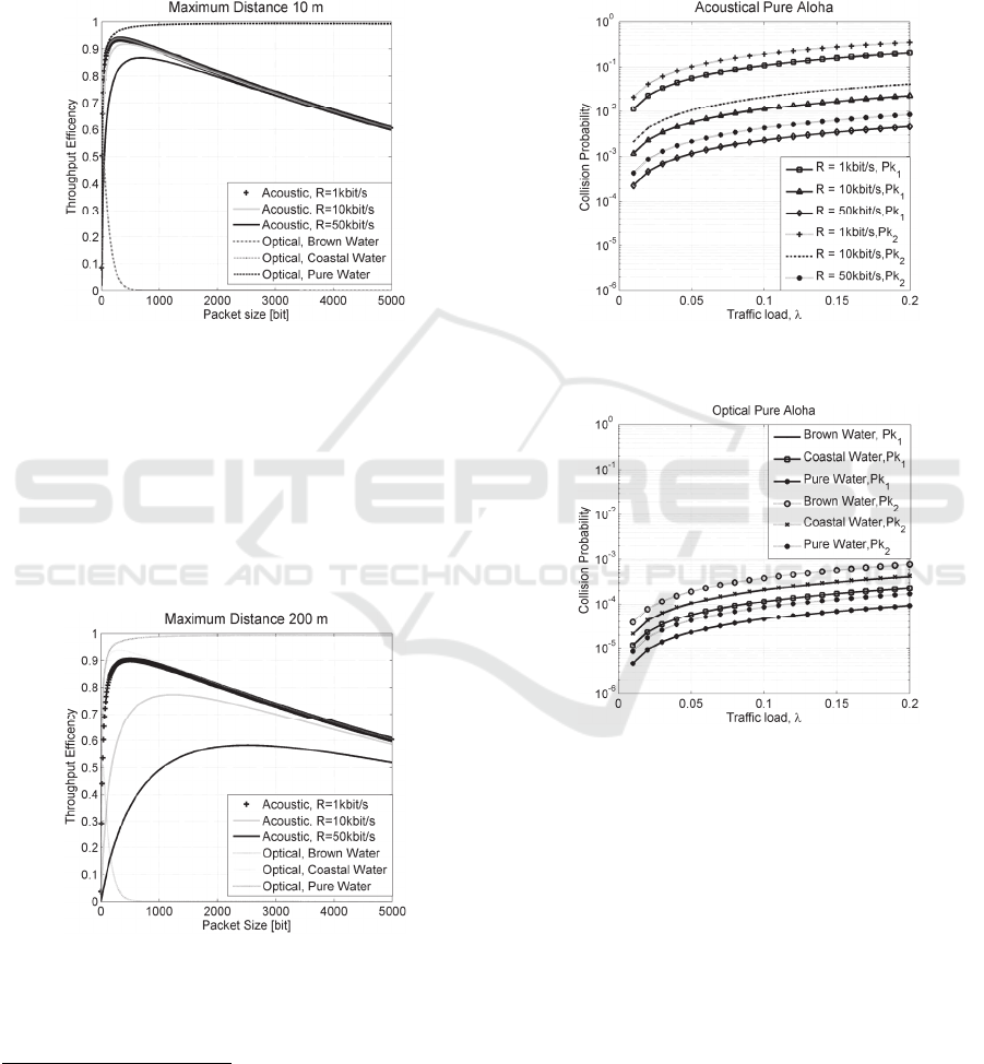
3.1 S&W Analysis
Throughput Efficiency, η, as a function of packet
size has been investigated for the different types of
scenario. Different maximum distances among the
nodes of the swarm have been considered, 10 m, and
200 m. We remind that, for such a type of scenario
the distances are very short, with high bit rates
compared to the typical underwater network
scenario. The parameters of the system are selected
as N
oh
=8, T
sync
= 16 T, and m =16. Obviously, at any
distance considered for the analysis, the maximum η
reachable for the optimum packet size has been
investigated. By simulations we found that for the
acoustic technology it is possible to delineate a
region of packet sizes in which good performances
are reachable (Figure 1), which is less than 500 bits.
As the packets dimension increases, the performance
decreases, especially when long distances are
considered (Figure 2) and high bit rate is assumed.
On the contrary, optical technology is able to reach
good performance regardless the maximum distance
and the data rates considered when the swarm
operates in clear water condition. When the turbidity
of the water increases, the optical technology
performances drastically decay up to communication
drop. It suggests that the acoustic technology is not
able to reach high data rates and thus is not able to
send complex data in real-time, but at the same time
is able to maintain communication among the swarm
regardless water condition and thus suitable when
optical communication is not applicable (i.e, brown
water closest port region).
3.2 MAC & Network Analysis
Two different versions of the Aloha protocol have
been considered and two different swarm
configurations have been investigated for the MAC
and Network analysis, respectively. In particular, we
analysed MAC performance by Collision Probability
evaluation versus different traffic loads, and
Network performance by Frame Error Probability
evaluation vs different packets dimension. For our
analysis, we have assumed that different
configurations correspond to different numbers of
hops needed to forward information from nodes to
the collecting node, i.e.: Pipeline: n
h
= N
AUV
-1; and
Dense Swarm n
h
<N
AUV
/2.
Collision Probability - The collision probability, P
c
,
has been evaluated by varying the traffic load and by
considering two exemplary packet dimensions that
are, according to the S&W analysis, (especially for
the acoustic case) less than 250bits, and thus Pk
1
=
100 bits and Pk
2
= 200 bits. By the analysis, we have
found that:
P
c
Pure Aloha: traffic load no more than λ=0.06
pkt/s seems to be more appropriate for this type of
network for the acoustic case, where the higher data
rate and the lower packet dimension permit to reach
suitable P
c
levels (Figure 3). Also in this analysis
clear water permits to reach better performance with
the optical technology, while brown water
experiments comparable performance with acoustic
R = 50 kbit/s case (Figure 4). We remind that the
effect of the water conditions in the optical case
leads to communication impairments among distant
nodes avoiding the participation of them to the
medium access contention, and thus it appears as a
Data Link Layer Effect over Swarm Underwater Network Performance
125
P
c
reduction when low traffic loads are considered.
This attitude is taken into account in the P
c
equation
(8) through n, the number of neighbour nodes that
want to access to the communication channels and
improve collision. Future works will consider a P
c
model where the turbidity of water will be explicitly
indicated.
Figure 1: η of S&W vs packet size N
d
for acoustic
(different data rates) and optical (different water)
technologies: at the maximum distance of 10 m.
P
c
Slotted Aloha: The collision probability has been
evaluated in the same condition of the Pure Aloha by
considering the Slotted scheme according to
equation (11) and, as expected, performance
improvement has been found for both technologies
(Figures 5 and 6).
Figure 2: η of S&W vs packet size N
d
for acoustic
(different data rates) and optical (different water)
technologies :at the maximum distance of 200 m.
Frame Error Probability – The FEP evaluations
have been performed for the two exemplary
configuration cases, by varying the packets
dimensions for two different traffic loads, λ=0.02
pkt/s (low traffic) and λ=0.2 pkt/s (high traffic) and
different data rates, R. System simulations have been
carried out for both Aloha schemes, Pure and
Slotted. As expected, the trends are the same, but
improvements are experimented for all cases under
test in Slotted solution. For this reason, only Slotted
Aloha evaluations are reported in this section. We
found that:
Figure 3: Collision Probability of Acoustic pure ALOHA
with different traffic load λ and packet data dimensions.
Figure 4: Collision Probability of Optical pure ALOHA
with different traffic load λ. and packet data dimensions.
Pipeline Configuration - For the Pipeline case
(Figure 7), where all nodes are involved in the
forwarding scheme, we found that, with low traffic
load, and low packets dimension (< 200 bits), it is
possible to reach suitable system performance level
for the acoustic case (FEP
Acoustic
≈ 10
-2
), even if the
optical technology shows better performance
(FEP
Optic
≈ 10
-3
) when clear water condition is
assumed regardless traffic load assumption (Figure
8). On the other hand, when brown water is
assumed, the acoustic technology seems to respond
better than the optical one (FEP
Optic
≈ 10
-1
). This
attitude is more remarkable when low traffic, and
very low packet size (< 100 bits) is adopted.
SENSORNETS 2016 - 5th International Conference on Sensor Networks
126
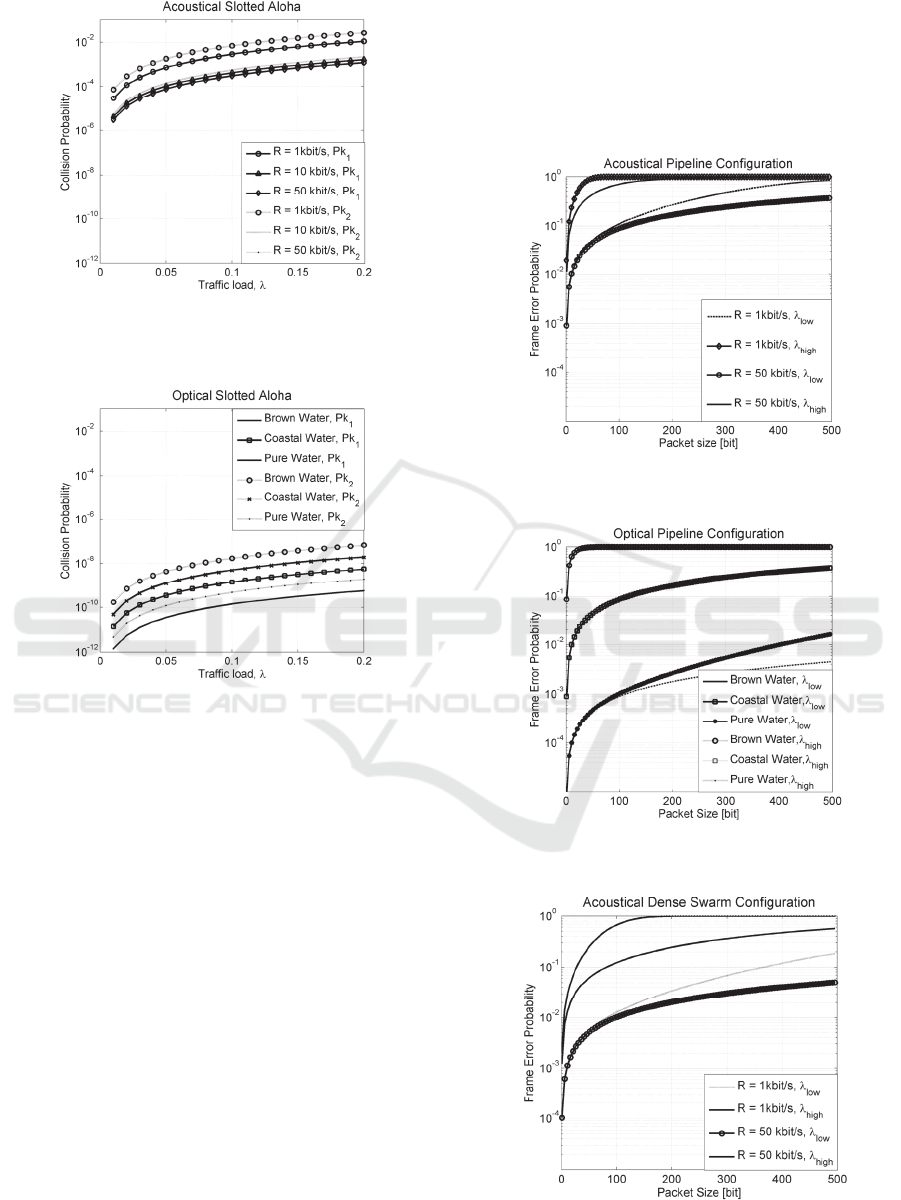
Figure 5: Collision Probability of Acoustic Slotted
ALOHA with different traffic load λ. and packet data
dimensions.
Figure 6: Collision Probability of Optical Slotted ALOHA
with different traffic load λ. and packet data dimensions.
Dense Swarm Configuration - For the Dense
Swarm case, we consider that only one hop is
needed to reach source to destination. As expected in
this case, the FEP is improved because the collision
probability is reduced with respect to the Pipeline
case. This trend becomes more evident with the
optical technology thanks to the better performance
of the optical channel (FEP
Optic
≈ 10
-4
) especially in
clear water (Figures 9 and 10). Even in this case, in
the brown water condition the enhancements of the
acoustic technology (FEP
Acoustic
≈ 10
-3
) with respect
to the optical one (FEP
Optic
≈ 10
-1
) become more
evident when low traffic and low data rate are
considered.
These evaluations suggest that, in the Pipeline
case, acoustic technology experiments no more high
performance, but it reaches a suitable level of
affordability in every water condition; in Dense
Swarm case, due to the reduced distance of the
nodes, the optical technology overcomes the
acoustic performance maintaining the minimum
affordability threshold needed regardless water
conditions. Finally, the performance investigated at
Network Layer level, confirmed the results at Data
Link Layer level: the optimum packet dimension
appears no more than 200 bits for every traffic load
considered.
Figure 7: FEP versus packet size with acoustic channel
and Slotted Aloha MAC (Pipeline Configuration).
Figure 8: FEP versus packet size with optical channel and
Slotted Aloha MAC (Pipeline).
Figure 9: FEP versus packet size with Acoustic channel
and Slotted Aloha MAC (Dense Swarm).
Data Link Layer Effect over Swarm Underwater Network Performance
127
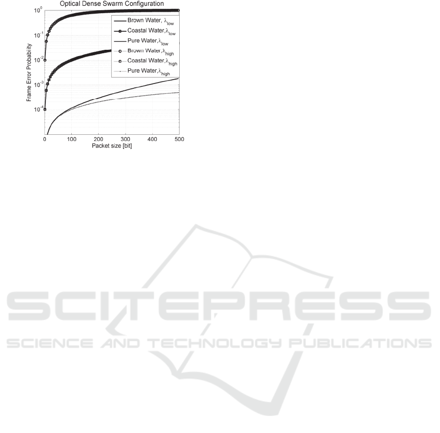
Figure 10: FEP versus packet size with Optical channel
and Slotted Aloha MAC (Dense Swarm).
4 CONCLUSIONS
A hybrid Underwater Swarm based on both acoustic
and optical technology has been investigated, taking
special attention for lower layers protocols able to
save energy, avoiding collisions and maximizing the
throughput. For this scope, an improved S&W
model, based on transmitting groups of packets for
which selective acknowledgments are generated, has
been investigated. Throughput Efficiency of these
types of protocols can be maximized by selecting an
optimal packet size as a function of the acoustic link
and optic link parameters. In addition, network
choices based on multi-hop solutions are
investigated by taking into account MAC constraints
in the network performance evaluation by
considering two different schemes: the Pure and
Slotted Aloha. Performance have been evaluated for
different swarm configurations, and results have
been investigated in terms of packet dimension and
maximum traffic tolerable. The obtained results
show that a packet size no more than 200 bits
permits to guarantee suitable system network
performance at both Data Link layer and Network
layer, for low traffic loads.
Actually, to fully utilize the limited resources of
an acoustic channel and to respond in efficient
manner to the optical water condition dependence,
further improvements of the protocol layer should be
taken into account by evaluating further MAC
schemes. In addition, future works will also consider
the scalability effect into network performance
evaluation by drastically increasing the number of
nodes in order to suggest useful indications for real
AUVs communication module implementation.
REFERENCES
Hon, S., et al. 2014. “Evaluation of Underwater Optical-
Acoustic Hybrid Network”, China Communications,
pp. 49-57.
Tabacchiera, M., Marchetti, E., Betti, S., and Persia, S.
2012. “Configuration effects over Swarm Underwater
Acoustic Network Performance,” SENSORCOMM
2012.
Proakis, J. G. 1989. “Digital Communications” 2nd Ed.,
McGraw-Hill.
Giles, J., and Bankman, I. 2005. “Underwater optical
communications systems – part 2: Basic design
considerations,” IEEE Military Communiations
Conference.
Xie, G., Gibson, J. 2001. “A Network Layer Protocol for
UANs to Address Propagation Delay Induced
Performance Limitations”, Proc. OCEANS 2001, vol.
4, pp. 2087--2094.
Stojanovic, M. 2005. “Optimization of a Data Link
Protocol for an Underwater Acoustic Channel”, Proc.
OCEANS 2005, vol. 1, pp. 68-73.
Vieira, L., Kong, J., Lee, U., Gerla, M. 2006. “Analysis of
Aloha Protocols for Underwater Acoustic Sensor
Networks,” in Poster abstract in ACM WUWNet,
2006, pp. 1–2.
Chirdchoo, N., Soh, W., Chua, K. 2007. “Aloha-based
MAC protocols with collision avoidance for
underwater acoustic networks,” in Proc. of INFOCOM
2007, pp. 2271–2275.
Lipsky, L. 2008. “Queueing Theory: A Linear Algebraic
Approach,” 2nd ed. New York: Springer-Verlag.
Zhu, Y., et al. 2013. “Toward Practical MAC Design for
Underwater Acoustic Networks,” INFOCOM 2013
Proceedings IEEE, April 2013, pp.683-691.
Stefanov, A., Stojanovic, M. 2011. ”Design and
Performance Analysis of Underwater Acoustic
Networks,” IEEE Journal on Selected Areas in
Communications (JSAC), Special Issue on Advances
in Military Communications and Networking, Vol. 29,
Issue 10, pp. 2012-2021.
SENSORNETS 2016 - 5th International Conference on Sensor Networks
128
