
Affine Invariant Self-similarity for Exemplar-based Inpainting
Vadim Fedorov
1
, Pablo Arias
2
, Gabriele Facciolo
3
and Coloma Ballester
1
1
Department of Information and Communication Technologies, University Pompeu Fabra, Barcelona, Spain
2
CMLA, ENS Cachan, Cachan, France
3
IMAGINE/LIGM,
´
Ecole Nationale des Ponts et Chauss
´
ees, Marne-la-Vall
´
ee, France
Keywords:
Image Inpainting, Self-similarity, Affine Invariance.
Abstract:
This paper presents a new method for exemplar-based image inpainting using transformed patches. We build
upon a recent affine invariant self-similarity measure which automatically transforms patches to compare them
in an appropriate manner. As a consequence, it intrinsically extends the set of available source patches to copy
information from. When comparing two patches, instead of searching for the appropriate patch transforma-
tion in a highly dimensional parameter space, our approach allows us to determine a single transformation
from the texture content in both patches. We incorporate the affine invariant similarity measure in a varia-
tional formulation for inpainting and present an algorithm together with experimental results illustrating this
approach.
1 INTRODUCTION
Image inpainting, also known as image completion or
disocclusion, refers to the recovery of occluded, miss-
ing or corrupted parts of an image in a given region
so that the reconstructed image looks natural. It has
become a key tool for digital photography and movie
post-production where it is used, for example, to elim-
inate unwanted objects that may be unavoidable dur-
ing filming.
Automatic image inpainting is a challenging task
that has received significant attention in recent years
from the image processing, computer vision, and
graphics communities. Remarkable progress has been
achieved with the advent of exemplar-based methods,
which exploit the self-similarity of natural images by
assuming that the missing information can be found
elsewhere outside the inpainting domain. Roughly
speaking, these methods work by copying patches
taken from the known part of the image and pasting
them smartly in the inpainting domain. These meth-
ods can obtain impressive results but many of them
rely on the assumption that the required information
can be copied as it is, without any transformations.
Therefore, applicability of such methods is limited to
the scenes in which objects are in a fronto-parallel po-
sition with respect to the camera.
In the image formation process, textured objects
may appear distorted by a projective transformation
Figure 1: Self-similarity under perspective distortion. The
human brain can easily fill-in missing information behind
the red rectangles in the examples above. We propose a
method able to automatically do the same for distortions
that can be locally approximated by an affinity.
(see Figure 1). This is a pervasive phenomenon in
our daily life. In fact, any person can mentally fill-in
occluded parts of an image, even if the missing in-
formation is available to them under a different per-
spective. Our brain is able to appropriately transform
the available information to match the perspective of
the occluded region. For instance in Figure 1 one can
easily infer what is hidden behind the red rectangle in
the graffiti scene on the right, or use the non-trivially
distorted context in the left image to fill-in the hole.
In this work we address this issue by transforming
known patches before pasting them in the inpainting
domain. The transformation is determined for each
patch in a fully automatic way. Moreover, instead
of searching for an appropriate transformation in a
highly dimensional space, our approach allows us to
determine a single transformation from a surrounding
texture content. As opposed to some previous works
50
Fedorov, V., Arias, P., Facciolo, G. and Ballester, C.
Affine Invariant Self-similarity for Exemplar-based Inpainting.
DOI: 10.5220/0005728100480058
In Proceedings of the 11th Joint Conference on Computer Vision, Imaging and Computer Graphics Theory and Applications (VISIGRAPP 2016) - Volume 3: VISAPP, pages 50-60
ISBN: 978-989-758-175-5
Copyright
c
2016 by SCITEPRESS – Science and Technology Publications, Lda. All rights reserved
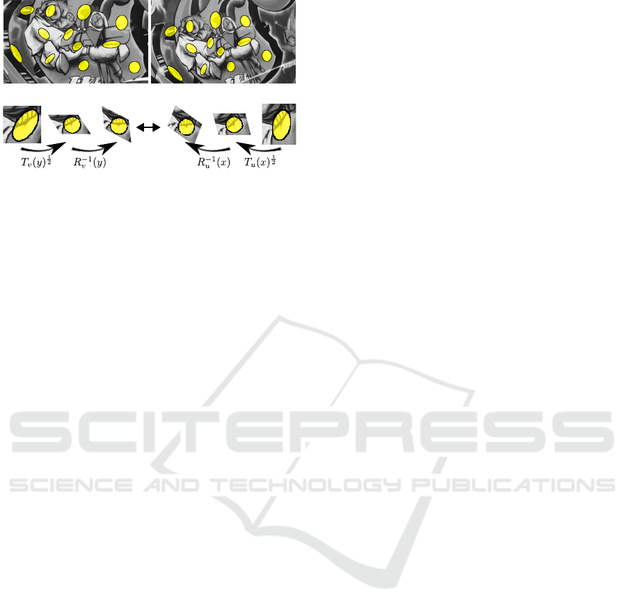
Figure 2: Affine covariant neighborhoods computed at cor-
responding points in two images taken from different view-
points. The neighborhoods are computed with the algorithm
described in Section 3. Note that, despite the change in ap-
pearance, the neighborhoods manage to capture the same
underlying texture. An affine invariant patch comparison is
achieved by normalizing the patches to circles and aligning
them with suitable rotations, as depicted in the diagram at
the bottom.
which only consider rotations and scalings, we can
handle full affinities, which in principle extends the
applicability of the method to any transformation that
can be locally approximated by an affinity, such as
perspective distortion.
We follow the approach recently proposed in (Fe-
dorov et al., 2015), where affine covariant tensor
fields computed a priori in each image are used to
define an affine invariant similarity measure between
patches. We incorporate this measure into a varia-
tional inpainting formulation. The affine covariant
tensors determine elliptical patches at each location of
the image domain. Due to the affine covariance prop-
erty of the tensors, these patches transform appropri-
ately when computed on an affinely transformed ver-
sion of the image. Figure 2 illustrates the patches de-
fined by the affine covariant tensors of (Fedorov et al.,
2015), computed for a set of corresponding points
in two images related by a homography. Note that
even though the transformation is not an affinity, the
patches still match, since a homography can be locally
approximated by an affinity.
The paper is organized as follows. Section 2 re-
views the related work. In Section 3, we summarize
the results of (Fedorov et al., 2015) which motivates
the definition of the similarity measure we use. Sec-
tion 4 is devoted to the inpainting method and algo-
rithm we propose. In Section 5 we present some ex-
periments asserting the validity of our theoretical ap-
proach together with a comparison with well-known
exemplar based methods. Finally, Section 6 con-
cludes the paper.
2 RELATED WORK
Most inpainting methods found in the literature can
be classified into two groups: geometry- and texture-
oriented depending on how they characterize the re-
dundancy of the image.
The geometry-oriented methods formulate the in-
painting problem as a boundary value problem and the
images are modeled as functions with some degree of
smoothness expressed, for instance, in terms of the
curvature of the level lines (Masnou and Morel, 1998;
Ballester et al., 2001; Masnou, 2002; Chan and Shen,
2001b; Cao et al., 2011), with propagation PDE’s
(Bertalm
´
ıo et al., 2000), or as the total variation of the
image (Chan and Shen, 2001a). These methods per-
form well in propagating smooth level lines or gradi-
ents, but fail in the presence of texture or big inpaint-
ing domains.
Exemplar-based (also called texture-oriented)
methods were initiated by the work of Efros and Le-
ung (Efros and Leung, 1999) on texture synthesis. In
that work the idea of self-similarity is exploited for di-
rect and non-parametric sampling of the desired tex-
ture. The self-similarity prior is one of the most influ-
ential ideas underlying the recent progress in image
processing and has been effectively used for differ-
ent image processing and computer vision tasks, such
as denoising and other inverse problems (Foi and Bo-
racchi, 2012; Buades et al., 2005; Gilboa and Osher,
2008; Peyr
´
e, 2009; Pizarro et al., 2010). It has also
found its application to inpainting: the value of each
target pixel x in the inpainting domain can be sampled
from the known part of the image or even from a vast
database of images (Hays and Efros, 2007).
The exemplar-based approach to inpainting has
been intensively studied (Demanet et al., 2003; Cri-
minisi et al., 2004; Wexler et al., 2007; Kawai et al.,
2009; Aujol et al., 2010; Arias et al., 2011). How-
ever, many such methods are based on the assumption
that the information necessary to complete the image
is available elsewhere and can be copied without any
modification but a translation.
Some works consider a broader family of transfor-
mations. Drori et al. (Drori et al., 2003) used heuris-
tic criteria to vary the scale of patches. Mansfield et
al. (Mansfield et al., 2011) and Barnes et al. (Barnes
et al., 2010) extended the space of available patches
by testing possible rotations and scales of a source
patch. The search in the space of available patches is
usually performed by a collaborative random search.
However, this implies that for each query patch, the
position of the matching patch as well as the param-
eters of the transformation (scale, rotation angle, tilt,
etc) must be determined. The high dimensionality of
Affine Invariant Self-similarity for Exemplar-based Inpainting
51

the parameter space makes the search problem very
computationally expensive and the excessive variabil-
ity of candidates may lead to unstable results. In
order to restrict the search space, authors of (Cao
et al., 2011) propose to combine an exemplar-based
approach that includes all rotated patches, with a geo-
metric guide computed by minimizing Euler’s elastica
of contrasted level lines in the inpainted region.
Several authors (Pavi
´
c et al., 2006; Huang et al.,
2013) have addressed this issue using some user inter-
action to guide the search process. For example, the
user provides information about the symmetries in the
image, or specifies 3D planes which are then used for
rectification and the rectified planes in turn are used
for searching for correspondences. Recently, Huang
et al. (Huang et al., 2014) proposed a method for auto-
matic guidance that searches for appropriately trans-
formed source patches. It starts by detecting planes
and estimating their projection parameters, which are
then used to transform the patches. This allows one
to handle perspective transformations, in situations
when representative planes can be detected.
Most of those works use a similarity measure,
either explicitly or implicitly, to compute a matching
cost between patches. We propose to use an affine
invariant similarity measure which automatically dis-
torts the patches being compared (Fedorov et al.,
2015). Our method considers a rich patch space that
includes all affine-transformed patches, however, for
each pair of patches the transformations are uniquely
determined using the image content. This effectively
limits the search space, making the method more sta-
ble. Since the patch distortions depend on the tex-
ture content of the image, our technique is related in
that sense to a shape-from-texture approach (G
˚
arding,
1992; G
˚
arding and Lindeberg, 1996; Ballester and
Gonzalez, 1998).
Let us remark that this similarity measure applies
to any transformation that can locally be approxi-
mated by an affinity. Moreover, since it has the same
complexity as the usual weighted Euclidean distance
between patches, it is thus well-suited for practical
applications.
In this paper we extend the variational framework
described in (Wexler et al., 2007; Kawai et al., 2009;
Arias et al., 2011) proposing a new energy and an
optimization algorithm for affine invariant exemplar-
based inpainting.
Let us finally note that (Wang, 2008) proposed
a self-similarity measure for image inpainting, com-
paring dense SIFT descriptors on square patches of a
fixed size. However, the method is not fully affine in-
variant, for example, neither the dense SIFT descrip-
tors nor the square patches are scale invariant. Several
authors have addressed the affine distortion and affine
invariance problem in other contexts such as image
comparison (Mikolajczyk and Schmid, 2004), object
recognition (Matas et al., 2004), and stereo (Garding
and Lindeberg, 1994).
3 AN AFFINE INVARIANT
SIMILARITY MEASURE
Non-local self-similarity is an accepted prior for nat-
ural images. To formalize it, a patch similarity or
comparison measure is needed. Let us consider the
general problem of comparing patches on two images
u : Ω
u
→ R and v : Ω
v
→ R, Ω
u
,Ω
v
⊆ R
2
. A widely
used comparison measure between two patches cen-
tered respectively at x and y is the weighted squared
Euclidean distance
D(t,x,y) =
Z
R
2
g
t
(h)(u(x + h) − v(y + h))
2
dh, (1)
where g
t
is a given window that we assume to be
Gaussian of variance t. The Gaussian g
t
represents
a weighted characteristic function of both patches be-
ing compared and determines the size of the patches
or, in other words, the scale.
In many occasions, similar patches exist in the im-
age but have undergone a transformation, for example
due to a different position with respect to the camera.
The Euclidean distance is not appropriate for detect-
ing these similarities. Consider for example a simple
case in which v is a rotated version of image u. If the
rotation is known, we should use the Euclidean dis-
tance between patches in u and rotated patches in v,
namely
D
R
(t,x,y) =
Z
R
2
g
t
(h)(u(x + h) − v(y + Rh))
2
dh.
(2)
In a more realistic scenario, one does not know the
appropriate transformation that matches both patches
being compared and even whether it exists. Some
previous works addressed this issue by searching
among all possible transformations (Barnes et al.,
2010; Mansfield et al., 2011) which involves probing
of all the parameters (scale, rotation angle, etc). The
high dimensionality of the parameter space makes the
problem very difficult. In this paper we use an affine
invariant similarity measure, introduced in (Fedorov
et al., 2015), that automatically deduces this transfor-
mation from the local texture context.
The similarity measure defined in (Fedorov et al.,
2015) is based on affine covariant tensor fields a pri-
ori computed in each image. It was derived as an ap-
proximation to a more general framework introduced
VISAPP 2016 - International Conference on Computer Vision Theory and Applications
52

in (Ballester et al., 2014), where similarity measures
between images on Riemannian manifolds are stud-
ied.
In the remainder of this section we present an
alternative, self-contained overview of this similar-
ity measure. We first briefly discuss the concept of
affine covariant tensors. Then we show how they are
used to define the affine invariant similarity measure
and establish the relation between our derivation and
the theory of (Ballester et al., 2014; Fedorov et al.,
2015). Finally, we describe an algorithm to compute
the affine convariant tensors.
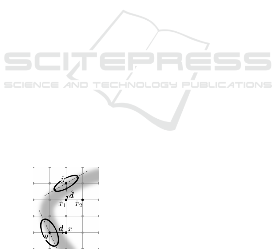
Affine Covariant Structure Tensors. We consider
an image-dependent tensor field T
u
as a function
that associates a tensor (a symmetric, positive semi-
definite 2 × 2 matrix) to each point x in the image do-
main. The tensor field is said to be affine covariant if
for any affinity A
T
u
A
(x) = A
T
T
u
(Ax)A, (3)
where u
A
(x) := u(Ax) denotes the affinely trans-
formed version of u. A geometric interpretation of
this property is the following. Given a tensor T
u
(x)
we can associate to it an elliptical region of “radius”
r centered at x
B
u
(x,r) = {y : hT
u
(x)(y − x), (y − x)i ≤ r
2
}. (4)
When the tensor is affine covariant, we have that
AB
u
A
(x,r) = B
u
(Ax,r). This implies that the tensors
can be used to define regions that transform appropri-
ately via an affinity (Figure 2).
The affine covariant tensors at two corresponding
locations allow to extract the affine distortion between
corresponding neighborhoods (or patches), up to a ro-
tation, as shown in (Fedorov et al., 2015). Indeed, for
any affine transformation A, there exists an orthogonal
matrix R such that
A = T
u
(Ax)
−
1
2
RT
u
A
(x)
1
2
. (5)
This last equation provides an intuitive geometric
relationship between the tensors, the associated ellip-
tical regions and the affinity. Consider a point x and
the corresponding affine covariant elliptic neighbor-
hood B
u
A
(x). Mapping B
u
A
(x) by the affinity yields
B
u
(Ax). The application of A can be decomposed in
three steps. First, applying T
u
(x)
1/2
, we transform
B
u
A
(x) into a circle or radius r. We refer to the re-
sulting patch as a normalized patch. Then, a rotation
is applied to the normalized patch. Finally, T
u
(Ax)
−
1
2
maps the rotated normalized patch to the elliptical
neighborhood B
u
(Ax).
To fully determine the affinity A, one needs to find
the rotation R. Any rotation would yield an affin-
ity that maps the elliptical neighborhood associated
to T
u
A
at x to the one associated to T
u
at Ax. For
a wrong value of the rotation, the image content in-
side both neighborhoods will not match. Therefore,
the right value for the rotation can be computed by
aligning the image content of both patches. For this
aim, we decompose the rotation as R = R
v
(y)R
−1
u
(x),
where R
v
(y) and R
u
(x) are estimated from the image
content in the patches. In practice, we calculate them
by aligning the dominant orientation of the normal-
ized patches to the horizontal axis. To compute the
dominant orientation we use histograms of gradient
orientations as in the SIFT descriptors (Lowe, 2004).
An Affine Invariant Patch Similarity. We are in-
terested in comparing the neighborhoods around two
points x, y defined in images u and v. The neighbor-
hoods are defined by the local metric given by the ten-
sors T
u
(x) and T
v
(y). In order to compare both neigh-
borhoods, a mapping between them is needed. Eq. (5)
suggest the following definition:
P
R
(x,y) = T
v
(y)
−
1
2
R
v
(y)R
−1
u
(x)T
u
(x)
1
2
. (6)
We can interpret P
R
(x,y) as an affinity, mapping the
elliptical patch associated to T
u
(x) into the one asso-
ciated to T
v
(y). If v is an affinely transformed version
of u, then P(x, y) recovers the true affinity. An affine
invariant patch similarity measure could be built by
computing the distance between the elliptical patch at
y and the result of applying P
R
(x,y) to the patch at
x. In practice, it is more suitable to transform both
neighborhoods to the circle of radius r (as depicted in
the second line of Figure 2) and compare the aligned
normalized patches:
D
a
(t,x,y) =
Z
∆
t
g
t
(h)·
u(x + T
−
1
2
u
R
u
(x)h) − v(y + T
−
1
2
v
R
v
(y)h)
2
dh, (7)
where ∆
t
is a disc centered at the origin with radius
proportional to the scale t and big enough such that
the weighting function g
t
has effective support in ∆
t
.
D
a
is an affine invariant patch distance which intrinsi-
cally extends the set of available patches. We will ap-
ply it in Section 4 to exemplar-based inpainting. Let
us also remark that formula (7) has the same complex-
ity of the patch comparison formula (1).
The similarity measure corresponding to (7) was
derived in (Fedorov et al., 2015) as a computationally
tractable approximation of the linear case of the mul-
tiscale similarity measures introduced in (Ballester
et al., 2014). There, the authors show that all scale
spaces of similarity measures D(t, x, y) satisfying a
set of appropriate axioms are solutions of a fam-
ily of degenerate elliptic partial differential equations
Affine Invariant Self-similarity for Exemplar-based Inpainting
53

(PDE). Images are considered in those papers as Rie-
mannian manifolds endowed with a metric defined by
a tensor field. If this tensor field is affine covariant,
the resulting similarity measure is affine invariant. In
this Riemannian framework P
R
defines an isometry
between the tangent spaces in two manifolds. The au-
thors refer to it as the a priori connection, since it is
related to the notion of connection appearing in paral-
lel transport (see (Ballester et al., 2014) for details).
WKB approximation method, named after
Wentzel, Kramers and Brillouin, was used in (Fe-
dorov et al., 2015) to find this approximate solution
to a linear partial differential equation with spa-
tially varying coefficients as a convolution with a
short-time space-varying kernel.
Computation of Affine Covariant Tensors. The
following iterative algorithm introduced in (Fedorov
et al., 2015) allows us to compute a dense field of
affine covariant tensors and the associated neighbor-
hoods on an image u
T
(k)
u
(x) =
R
B
(k−1)
u
(x,r)
Du(y) ⊗ Du(y)dy
Area(B
(k−1)
u
(x,r))
, (8)
where B
(k)
u
is the elliptical region associated to T
k
u
given by (4) for k ≥ 2, and B
(0)
u
(x,r) = {y : |Du(x)(y −
x)| ≤ r} for k = 1.
In this paper we follow the notation of (Fedorov
et al., 2015) and denote by T
u
(x) the affine covariant
structure tensor T
(k)
u
(x) for a fixed value of k (k = 30)
and a given value of r (r > 0 is a free parameter which
is in range [250, 350] in our experiments). We denote
by B
u
(x) the affine covariant neighborhood B
(k)
u
(x,r).
To simplify notation in the following sections,
we are going to assume that R
u
= Id and R
v
= Id.
In order to stress that D
a
in (7) refers to a patch
distance, we will use interchangeably D
a
(t,x,y) or
D
a
t
(p
u
(x), p
v
(y)), where p
u
(x) denotes the elliptic
patch centered at x. The patch p
u
(x) := p
u
(x,·) is de-
fined by p
u
(x,h) := u(x +T
u
(x)
−
1
2
h), where h belongs
to a disc centered at 0 ∈ R
2
. Note that the scale t in
(7) reflects the support of the Gaussian g
t
and, hence,
the size of the patch used for the comparison.
4 INPAINTING FORMULATION
Exemplar-based inpainting methods aim at filling-in
the image so that each patch in the inpainting domain
is similar to some known patch. This requires com-
paring known patches with partially or completely un-
known patches. For this we extend the variational
framework described in (Wexler et al., 2007; Kawai
et al., 2009; Arias et al., 2011) by using the affine
invariant similarity measure D
a
t
given in (7). We for-
mulate the problem of inpainting from affinely trans-
formed patches via the minimization of the following
energy functional
E(u,ϕ) =
Z
e
O
D
a
t
(p
u
(x), p
ˆu
(ϕ(x))) dx, (9)
where O ⊂ Ω ⊂ R
2
is the inpainting domain, ˆu : Ω \
O → R is the known part of the image,
e
O includes all
the centers of patches intersecting O (i.e., the centers
of unknown patches) and
e
O
c
is its complement, i.e.
the centers of fully known patches. The minimization
of (9) aims at finding a visually plausible completion
u of ˆu in the unknown region O. While the additional
variable ϕ :
e
O →
e
O
c
determines, for each unknown
target patch, the location of a source patch from which
the information will be copied.
This energy compares patches defined on elliptic
domains centered at x and ϕ(x). In the known part
of the image, these domains are defined by the affine
structure tensors T
ˆu
. Since the image is unknown in-
side the inpainting domain we have to estimate the
tensors together with the image. The relationship be-
tween u and T
u
introduces a complexity in the mini-
mization of (9). Therefore, we propose to relax it and
consider the minimization of the energy
e
E(u,ϕ,G) =
Z
e
O
Z
∆
t
g
t
(h)
u(x + G(x)
−
1
2
h) − ˆu(ϕ(x) + T
ˆu
(ϕ(x))
−
1
2
h)
2
dhdx
(10)
where G(x) is an invertible 2 × 2 matrix, ∀x ∈
e
O. For
now, we will not restrict the tensor field G to be given
by the affine structure tensors T
u
. Instead, we consider
them as an additional variable, in principle indepen-
dent of u. In this way, we do not have to deal with the
complex dependency between T
u
and u. In practice,
due to the properties of the affine structure tensors, it
turns out that the G can be estimated from T
u
(x), as
will be explained in the next section.
4.1 Approximate Minimization
Algorithm
We compute a local minimum of the energy with an
alternating optimization scheme on the variables u, G
and ϕ.
VISAPP 2016 - International Conference on Computer Vision Theory and Applications
54

Image Update Step. In the image update step, ϕ
and G are fixed, and the energy is minimized with
respect to u. With the change of variables z = x +
G(x)
−
1
2
h, the Euler-Lagrange equation leads to the
following expression:
u(z) =
1
C(z)
Z
e
O
g
t
(G(x)
1
2
(z − x))
ˆu
ϕ(x) + T
ˆu
(ϕ(x))
−
1
2
G(x)
1
2
(z − x)
|G(x)
1
2
|dx,
(11)
where C(z) is normalization factor such that the sum
is an average. The field G determines elliptic patches
centered at each x ∈
e
O. For each one of these patches
a matching patch centered at ϕ(x) is known, as well
as its shape which is given by tensor T
ˆu
(ϕ(x)). The
corresponding patch is then warped via the affinity
P(x,ϕ(x)) = T
ˆu
(ϕ(x))
−
1
2
G(x)
1
2
, and aggregated in the
inpainting domain. Note that if G(x) = T
u
(x), then
P(x,ϕ(x)) coincides with Eq. (6) (recall that for sim-
plicity in the presentation we are assuming that the
rotations in Eq. (6) are the identity).
Affine Correspondence Update Step. Given a
fixed u, the minimization with respect to (ϕ,G) can
be performed by independently minimizing the patch
error function D
a
t
for each x ∈
e
O. This problem is
very complex to solve since it is a nearest neighbor
search where we also optimize for the affine transfor-
mation of the patch at x, given by G.
We will exploit the properties of the affine struc-
ture tensors to estimate an approximate solution. For
that, let us consider a completion candidate u and as-
sume that a local vicinity of x on u is an affinely
transformed version of a local vicinity of ϕ(x) on
ˆu. That is, u(x + h) = ˆu(ϕ(x) + Ah), which is the
case when x and ϕ(x) do actually correspond. Set-
ting G(x) such that T
ˆu
(ϕ(x))
−
1
2
G
1
2
(x) = A will lead
to a correct mapping and zero patch distance. On
the other hand, using (6) we can find this affinity as
A = T
ˆu
(ϕ(x))
−
1
2
RT
u
(x)
1
2
where R is some orthogonal
Algorithm 1: Approximate minimization of
e
E(u,ϕ, G).
Require: Initial condition u
0
at O, tolerance τ > 0.
1: repeat
2: Compute affine structure tensors T
u
k−1
(x) and
rotations R
k−1
(x) for all x ∈
e
O.
3: Estimate optimal correspondences ϕ
k
using the
modified PatchMatch (see Sect 4.2).
4: Update image: u
k
= argmin
u
e
E(u,ϕ
k
,G
k
), sub-
ject to u
k
= ˆu in O
c
.
5: until ku
k
− u
k−1
k < τ.
2×2 matrix and T
u
is calculated on u. Then G(x) such
that G
1
2
(x) = R(x)T
1
2
u
(x), together with ϕ(x), will be
global minimizers of the patch error function D
a
t
at
x. Therefore, we need to search only for ϕ(x) and
R(x). An approximate ϕ(x) can be found efficiently
using our modified version of the PatchMatch algo-
rithm (Barnes et al., 2009), detailed in Section 4.2,
and the additional rotation R(x) can be determined as
described in Section 3. Of course, if the neighbor-
hood of x does not match any affinely transformed
patch, then the estimated G might not minimize the
patch error function D
a
t
.
Another interpretation of the approximate mini-
mization can be given by adding to the minimization
of
e
E(u,ϕ,G) the constraint that G
1
2
(x) = R(x)T
1
2
u
(x)
for all x ∈
e
O and for some rotation matrix R(x),
namely,
min
e
E(u,ϕ,G) subject to G
1
2
= R
−1
u
T
1
2
u
.
The correspondence update step corresponds to the
constrained minimization of the energy with respect
to ϕ,G for a fixed image u. In the image update step
the energy is minimized with respect to u, but with-
out enforcing the constraint. Therefore, our approxi-
mate minimization can be seen as an alternating min-
imization applied to a constrained problem. The con-
straint is enforced only when minimizing with one of
the variables (the pair ϕ,G). There are no theoretical
guarantees for the convergence of such a scheme, al-
though we have not yet encountered a practical case
where the algorithm failed to converge.
4.2 Implementation Details
Image Update Step. The actual implementation of
(11) is
u(z) =
1
C(z)
∑
x∈
e
O
g
t
(T
1
2
u
(x)(z − x)) m
c
(x)w(x,ϕ(x))
ˆu
ϕ(x) +
e
P
R
(x,ϕ(x))(z − x)
|T
1
2
u
(x)|, (12)
where
e
P
R
(x,ϕ(x)) = T
−
1
2
ˆu
(ϕ(x))RT
1
2
u
(x) is the esti-
mated a priory connection between x and ϕ(x). The
tensor field T
u
is computed using the inpainted image
u from the previous iteration. m
c
is a confidence mask
that takes values from 1 to 0, decreasing with the dis-
tance to the set of known pixels O
c
. This mask is
usual in exemplar-based inpainting, e.g. (Arias et al.,
2011), since it helps to guide the flow of information
from the boundary towards the interior of the inpaint-
ing domain, eliminating some local minima and re-
ducing the effect of the initial condition. Finally, let
Affine Invariant Self-similarity for Exemplar-based Inpainting
55
us comment on the additional weight w(x,ϕ(x)). Usu-
ally, all patches containing a pixel z contribute to its
color value. To control the amount of contributors,
we introduce an auxiliary Gaussian weight w(x, ϕ(x))
that depends on our patch distance D
a
(t,x,ϕ(x)). It
allows us to cut off contributors with low similarity
(high distance) values, which in turn results in sharper
reconstructions.
The energy (9) is non-convex and has several lo-
cal minimia. As a consequence, there is a dependency
on the initialization. To alleviate this dependency, we
aid the propagation of information from the boundary
towards the interior of the inpainting domain in the
following way. Recall that the extended domain
e
O
contains the centers of all ellipses overlapping the in-
painting domain. We dilate
e
O a few pixels to capture
a narrow band around the inpainting domain of com-
pletely known elliptic patches. Since these patches do
not intersect the inpainting domain, they do not yet
contribute to the inpainting. For these pixels, during
the image update step we extend their neighborhoods
by setting a larger radius value 2r (for this we do
not recompute the tensors, therefore, we only change
the size but not the shape of the associated neighbor-
hood). This results in bigger ellipses, which now may
overlap the domain. This boosts the information prop-
agation at the boundaries of the inpainting domain
during the very first iterations of inpainting.
Affine Correspondence Update Step. During the
update of the correspondence map we compute an ap-
proximation of the nearest neighbor field using Patch-
Match (Barnes et al., 2009; Barnes et al., 2010). The
PatchMatch algorithm speeds up the computation of
optimal correspondences by exploiting the correla-
tion between patches so that they can be found col-
lectively. Since we are working with elliptic patches
which might be arbitrarily rotated, we adapt the
PatchMatch propagation scheme to take it into ac-
count. Let x be the current pixel and d
1
= (±1,0),
Figure 3: Propagation directions in the modified scheme.
d
2
= (0, ±1) be the directions of propagation. Then,
the adjacent pixels y
i
= x −d
i
(i = 1,2) are tested dur-
ing the propagation. Assume i = 1 (see Figure 3).
Pixel ˆy = ϕ(y) is the current nearest neighbor can-
didate for y. The standard PatchMatch would try to
propagate position ˆy + d to pixel x. In contrast, we
calculate the direction
ˆ
d =
e
P
R
(y, ˆy)d, where
e
P
R
(·,·) is
the a priori connection, and we try a few positions
along that direction. This generalization gives more
meaningful propagation along edges.
At early iterations of our algorithm, the inpainted
image may be blurry. It comes from inconsistency
between color values proposed for filling-in pixels
in the inpainting domain. As discussed in (Fedorov
et al., 2015), the tensors are sensitive to blur, tending
to larger neighbourhoods in blurry regions. To com-
pensate for this, we allow the parameter r (in equa-
tion 8) to vary during the correspondence map estima-
tion. That is, while T
ˆu
(ϕ(x)) is always computed with
the fixed r, say r
0
(a given parameter of the method),
in the computation of T
u
(x) we consider a few val-
ues of r smaller than r
0
(around 5) and select the one
giving the smallest patch distance D
a
t
between p
u
(x)
and p
ˆu
(ϕ(x)). Let us note, that to be able to compare
patches, computed with different values of r, we scale
the normalized circles to circles of radius one.
5 EXPERIMENTAL RESULTS
In this section we present results obtained by the pro-
posed method. For all the experiments in this section,
we compare our results with the ones obtained by the
multiscale NL-Means method (Wexler et al., 2007;
Kawai et al., 2009) which we find to be a representa-
tive exemplar-based image inpainting method operat-
ing with only translations of patches. Whenever pos-
sible, we also compare against the method of (Mans-
field et al., 2011) with a single scale and considering
rotations, and the method of (Huang et al., 2014). In
both cases we use the authors’ implementations.
As a sanity check we first test the proposed
method on a synthetic example, displayed in Figure 4.
We take a textured image and create an affinely trans-
formed version of it. We select a part of the trans-
formed image as the inpainting domain. Instead of
using the rest of the transformed image to copy in-
formation from, we make the original (not trans-
formed) image to be the source. Let us remark that the
ground truth affinity is not provided to the algorithm,
hence, we test the ability of the proposed method to
identify and copy affinely transformed patches. We
do not show any results for (Mansfield et al., 2011)
and (Huang et al., 2014) for this experiment, since the
VISAPP 2016 - International Conference on Computer Vision Theory and Applications
56
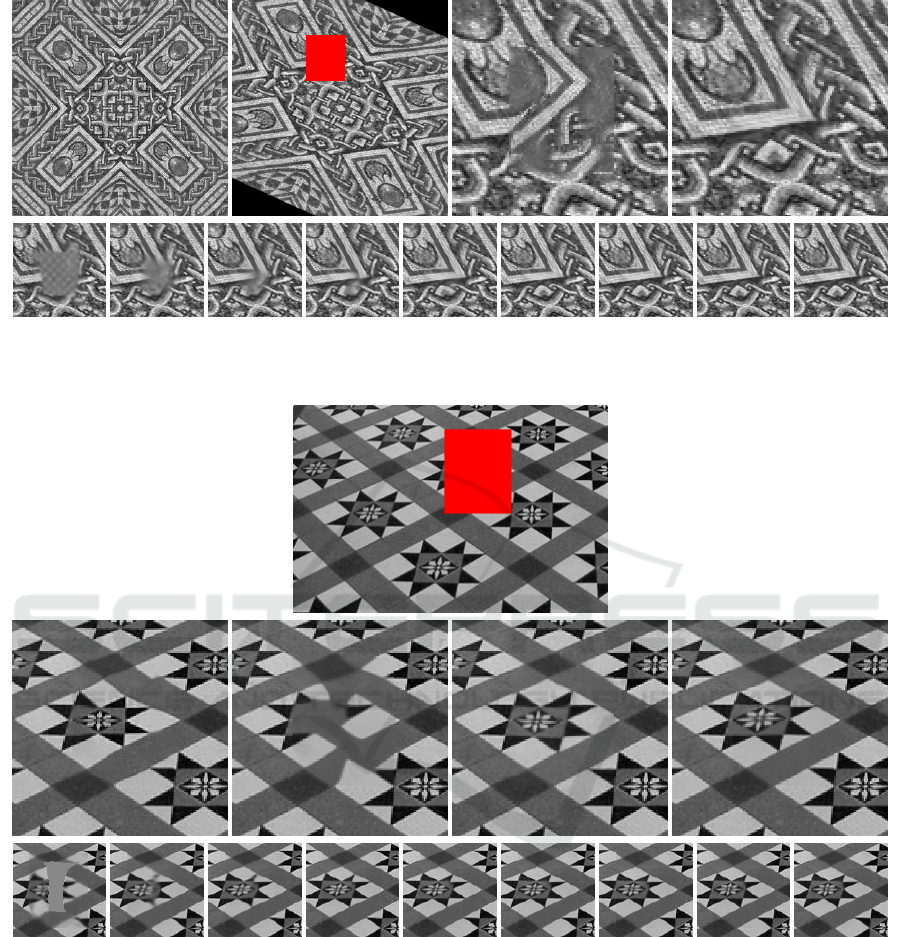
Figure 4: First row: source image, target image with the inpainting domain shown in red, and close-ups around the inpainting
area of the NL-Means result and the result of our method. Second row: evolution of the inpainting domain over iterations of
our method (every third iteration).
Figure 5: First row: image with the inpainting domain shown in red. Second row: close-ups around the inpainting area of
the NL-Means result, the result of (Mansfield et al., 2011) (considering rotations), the result of (Huang et al., 2014), and the
result of our method. Third row: evolution of the inpainting domain over iterations of our method (every third iteration).
available implementations do not support the use of a
separate image as a source.
A more realistic case would be associated with a
more general transformation. Since for planar objects
a projective transformation can be locally approxi-
mated by an affinity, in the second example (shown
in Figure 5) we test the robustness of our method
in the reconstruction of an image distorted by per-
spective. As usual in inpainting applications, in this
experiment we use the known part of the image as
source. We compare our method with the NL-Means
method, that works only with translations, and addi-
tionally with the method of (Mansfield et al., 2011)
in the mode when the rotations are also considered,
and the method of (Huang et al., 2014). Note that the
latter method successfully determines a single plane
in the image and, as expected, achieves a good recon-
struction.
Affine Invariant Self-similarity for Exemplar-based Inpainting
57
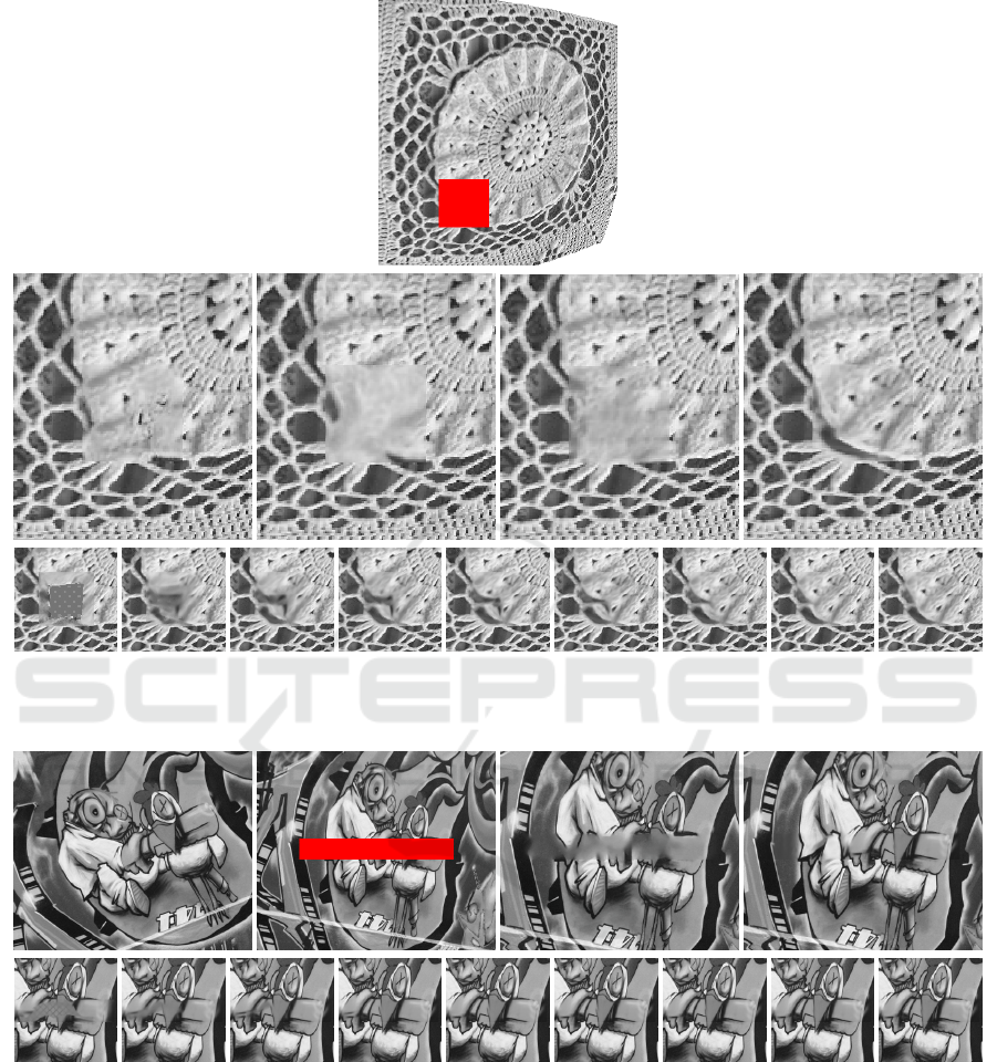
Figure 6: First row: image with the inpainting domain shown in red. Second row: close-ups around the inpainting area of
the NL-Means result, the result of (Mansfield et al., 2011) (considering rotations), the result of (Huang et al., 2014), and the
result of our method. Third row: evolution of the inpainting domain over iterations of our method (every third iteration).
Figure 7: First row: source image, target image with the inpainting domain shown in red, and close-ups around the inpainting
area of the NL-Means result and the result of our method. Second row: evolution of the inpainting domain over iterations of
our method (every third iteration).
The third example (Figure 6) demonstrates the re-
construction of a texture with some lens distortion ap-
plied to it. The known part of the image is used as a
source and, like in all other experiments, just a ro-
tation of source patches is not sufficient to obtain a
good result. As in the previous case, here we com-
pare our method with the NL-Means method (transla-
tions), the method of (Mansfield et al., 2011) (transla-
tions and rotations), and the method of (Huang et al.,
2014) (projective transformation).
A final experiment, which is also potentially in-
teresting for real applications, consists in inpainting
one view of a scene using information from another
view of the same scene. Figure 7 shows the results of
this experiment where we have applied the proposed
method to two views related by an unknown homog-
VISAPP 2016 - International Conference on Computer Vision Theory and Applications
58

raphy. As before, we compare our result with the re-
sult of the NL-Means method.
Let us finally note that the method of (Mansfield
et al., 2011) also supports rotations plus scalings.
However, we could not obtain meaningful results on
these examples for this mode. It seems that the addi-
tional variability added by the scalings makes it eas-
ier for the algorithm to be trapped in a bad local mini-
mum. For example, a constant region can be produced
by scaling a small uniform patch.
6 CONCLUSIONS
In this work we propose a new variational formula-
tion for exemplar-based inpainting that, for the first
time, considers local full affine transformations with
a tractable approximate optimization scheme. This is
possible thanks to the use of the affine covariant ten-
sors and the associated affine invariant metric, both
introduced in (Fedorov et al., 2015). These tensors
provide an efficient way to determine a unique affin-
ity putting in correspondence any pair of patches. If
the patches being compared are related by an affinity,
then this affinity is recovered.
The problem of exemplar-based inpainting is a
complex non-convex problem with many local min-
ima. As pointed out in (Cao et al., 2011), adding
transformations of patches makes it even more com-
plex. Intuitively, the added variability makes it harder
to distinguish “good” minima from other minima (a
single pixel can be scaled to match a constant patch).
We believe that the tensors are beneficial in this re-
spect, because they constrain the number of ways in
which a source patch can be transformed to match a
target patch, thus eliminating some of the variability.
This also allows us to design faster and more accurate
minimization algorithms without the need to search
the parameter space of the transformation family.
The proposed method works at a single scale. To
better handle larger inpainting domains it would be
desirable to develop a multiscale scheme, as is cus-
tomary in the literature (Wexler et al., 2007; Kawai
et al., 2009; Arias et al., 2011). However, extend-
ing the multiscale approach to the problem of inpaint-
ing using affinely transformed patches is not trivial,
since the filtering with an isotropic Gaussian breaks
the affine invariance. Adapting multiscale inpainting
approaches to this context is an interesting direction
for future research.
ACKNOWLEDGEMENTS
The first, the second and the fourth authors acknowl-
edge partial support by MICINN project, reference
MTM2012-30772, and by GRC reference 2014 SGR
1301, Generalitat de Catalunya.
The second and third authors were partly founded
by the Centre National d’Etudes Spatiales (CNES,
MISS Project), BPIFrance and Rgion Ile de France, in
the framework of the FUI 18 Plein Phare project, the
European Research Council (advanced grant Twelve
Labours n246961), the Office of Naval research
(ONR grant N00014-14-1-0023), and ANR-DGA
project ANR-12-ASTR-0035.
REFERENCES
Arias, P., Facciolo, G., Caselles, V., and Sapiro, G. (2011).
A variational framework for exemplar-based image in-
painting. International Journal of Computer Vision,
93:319–347.
Aujol, J.-F., Ladjal, S., and Masnou, S. (2010). Exemplar-
based inpainting from a variational point of view.
SIAM Journal on Mathematical Analysis, 42(3):1246–
1285.
Ballester, C., Bertalm
´
ıo, M., Caselles, V., Sapiro, G., and
Verdera, J. (2001). Filling-in by joint interpolation of
vector fields and gray levels. IEEE Transactions on
Image Processing, 10(8):1200–1211.
Ballester, C., Calderero, F., Caselles, V., and Facciolo, G.
(2014). Multiscale analysis of similarities between
images on riemannian manifolds. SIAM Journal Mul-
tiscale Modeling and Simulation, 12(2):616–649.
Ballester, C. and Gonzalez, M. (1998). Affine invariant
texture segmentation and shape from texture by varia-
tional methods. Journal of Mathematical Imaging and
Vision, 9(2):141–171.
Barnes, C., Shechtman, E., Finkelstein, A., and Goldman,
D. B. (2009). PatchMatch: a randomized correspon-
dence algorithm for structural image editing. In ACM
SIGGRAPH 2009 Papers, pages 1–11. ACM.
Barnes, C., Shechtman, E., Goldman, D. B., and Finkel-
stein, A. (2010). The generalized PatchMatch cor-
respondence algorithm. In European Conference on
Computer Vision.
Bertalm
´
ıo, M., Sapiro, G., Caselles, V., and Ballester, C.
(2000). Image inpainting. In Proceedings of SIG-
GRAPH,, pages 417–424.
Buades, A., Coll, B., and Morel, J.-M. (2005). A non local
algorithm for image denoising. In Proceedings of the
IEEE Conference on CVPR, volume 2, pages 60–65.
Cao, F., Gousseau, Y., Masnou, S., and Prez, P. (2011). Ge-
ometrically guided exemplar-based inpainting. SIAM
Journal on Imaging Sciences, 4(4):1143–1179.
Chan, T. and Shen, J. H. (2001a). Mathematical models
for local nontexture inpaintings. SIAM J. App. Math.,
62(3):1019–43.
Affine Invariant Self-similarity for Exemplar-based Inpainting
59

Chan, T. and Shen, J. H. (2001b). Nontexture inpainting by
curvature-driven diffusions. Journal of Visual Com-
munication and Image Representation, 12(4):436–
449.
Criminisi, A., P
´
erez, P., and Toyama, K. (2004). Region fill-
ing and object removal by exemplar-based inpainting.
IEEE Trans. on IP, 13(9):1200–1212.
Demanet, L., Song, B., and Chan, T. (2003). Image in-
painting by correspondence maps: a deterministic ap-
proach. Applied and Computational Mathematics,
1100:217–50.
Drori, I., Cohen-Or, D., and Yeshurun, H. (2003).
Fragment-based image completion. In ACM SIG-
GRAPH 2003 Papers, volume 22, pages 303–12.
Efros, A. A. and Leung, T. K. (1999). Texture synthesis by
non-parametric sampling. In Proceedings of the IEEE
ICCV, pages 1033–38.
Fedorov, V., Arias, P., Sadek, R., Facciolo, G., and
Ballester, C. (2015). Linear multiscale analysis of
similarities between images on riemannian manifolds:
Practical formula and affine covariant metrics. SIAM
Journal on Imaging Sciences, 8(3):2021–2069.
Foi, A. and Boracchi, G. (2012). Foveated self-similarity
in nonlocal image filtering. Human Vision and Elec-
tronic Imaging XVII, 8291(1):829110.
Garding, J. and Lindeberg, T. (1994). Direct estimation of
local surface shape in a fixating binocular vision sys-
tem. In Eklundh, Lecture Notes in Computer Science,
pages 365–376.
Gilboa, G. and Osher, S. J. (2008). Nonlocal operators with
applications to image processing. Multiscale Model-
ing and Simulation, 7(3):1005–1028.
G
˚
arding, J. (1992). Shape from texture for smooth curved
surfaces in perspective projection. Journal of Mathe-
matical Imaging and Vision, 2(4):327–350.
G
˚
arding, J. and Lindeberg, T. (1996). Direct computation
of shape cues using scale-adapted spatial derivative
operators. International Journal of Computer Vision,
17(2):163–191.
Hays, J. and Efros, A. (2007). Scene completion using mil-
lions of photographs. In SIGGRAPH, New York, NY,
USA. ACM.
Huang, J.-. B., Kopf, J., Ahuja, N., and Kang, S. B. (2013).
Transformation guided image completion. In Inter-
national Conference on Computational Photography,
pages 1–9.
Huang, J. B., Kang, S. B., Ahuja, N., and Kopf, J. (2014).
Image completion using planar structure guidance.
ACM Transactions on Graphics (Proceedings of SIG-
GRAPH 2014), 33(4):129:1–129:10.
Kawai, N., Sato, T., and Yokoya, N. (2009). Image inpaint-
ing considering brightness change and spatial locality
of textures and its evaluation. In Advances in Image
and Video Technology, pages 271–282.
Lowe, D. (2004). Distinctive image features from scale-
invariant keypoints. International Journal of Com-
puter Vision, 60(2):91–110.
Mansfield, A., Prasad, M., Rother, C., Sharp, T., Kohli, P.,
and van Gool, L. (2011). Transforming image comple-
tion. In Proceedings of BMVC, pages 121.1–121.11.
Masnou, S. (2002). Disocclusion: a variational approach
using level lines. IEEE Transactions on Image Pro-
cessing, 11(2):68–76.
Masnou, S. and Morel, J.-M. (1998). Level lines based dis-
occlusion. In Proceedings of IEEE ICIP, volume 3,
pages 259–263.
Matas, J., Chum, O., Urban, M., and Pajdla, T. (2004).
Robust wide-baseline stereo from maximally stable
extremal regions. Image and Vision Computing,
22(10):761–767.
Mikolajczyk, K. and Schmid, C. (2004). Scale & affine in-
variant interest point detectors. International Journal
of Computer Vision, 60(1):63–86.
Pavi
´
c, D., Schonefeld, V., and Kobbelt, L. (2006). Inter-
active image completion with perspective correction.
The Visual Computer, 22(9-11):671–681.
Peyr
´
e, G. (2009). Manifold models for signals and im-
ages. Computer Vision and Image Understanding,
113(2):249–260.
Pizarro, L., Mr
´
azek, P., Didas, S., Grewenig, S., and Weick-
ert, J. (2010). Generalised nonlocal image smoothing.
International Journal of Computer Vision, 90:62–87.
Wang, Z. (2008). Image affine inpainting. In Image Analy-
sis and Recognition, volume 5112 of Lecture Notes in
Computer Science, pages 1061–1070.
Wexler, Y., Shechtman, E., and Irani, M. (2007). Space-time
completion of video. IEEE Transactions on PAMI,
29(3):463–476.
VISAPP 2016 - International Conference on Computer Vision Theory and Applications
60
