Vision-based Robotic System for Object Agnostic Placing Operations
Nikolaos Rofalis
1
, Lazaros Nalpantidis
1
, Nils Axel Andersen
2
and Volker Kr
¨
uger
1
1
Dept. of Mechanical and Manufacturing Engineering, Aalborg University, Aalborg, Denmark
2
Dept. of Electrical Engineering, Technical University of Denmark, Kgs. Lyngby, Denmark
Keywords:
Industrial Robots, Object Detection, Object Matching, Grasping, Placing, Kitting.
Abstract:
Industrial robots are part of almost all modern factories. Even though, industrial robots nowadays manipulate
objects of a huge variety in different environments, exact knowledge about both of them is generally assumed.
The aim of this work is to investigate the ability of a robotic system to operate within an unknown environment
manipulating unknown objects. The developed system detects objects, finds matching compartments in a
placing box, and ultimately grasps and places the objects there. The developed system exploits 3D sensing
and visual feature extraction. No prior knowledge is provided to the system, neither for the objects nor for
the placing box. The experimental evaluation of the developed robotic system shows that a combination of
seemingly simple modules and strategies can provide effective solution to the targeted problem.
1 INTRODUCTION
Even if robots are evolving rapidly, the level of au-
tomation in manufacturing can in reality be very low.
As evidenced by the EU project STAMINA (Sustain-
able and reliable robotics for part handling in manu-
facturing automation), part handling across the vari-
ous assembly stages in the automotive industry is the
task with the lowest automation levels—below 30%
1
.
This fact comes as the result of two factors. First, pro-
duction lines and handled parts in industry are charac-
terized by large diversity. Second, most robotic sys-
tems deployed in industry require pre-specified struc-
tured environments and can only manipulate a priori
known objects. Thus, it becomes evident that au-
tomated systems need to evolve and become more
flexible requiring less—or even no—prior knowledge
about their environment and the objects to be handled.
In this work we present the development of an in-
dustrial robotic system that is able to operate within
an uncertain environment and manipulate unknown
objects. We focus on automating part handling tasks,
as an indicative industrial task that will have an effect
on various industrial sectors—including the automo-
tive industry. A relevant such task is kitting— a con-
cept whose automation is pursued in the STAMINA
project. Kitting boxes are placed on the chassis of
each car in the production line, containing parts that
1
http://stamina-robot.eu/about-stamina
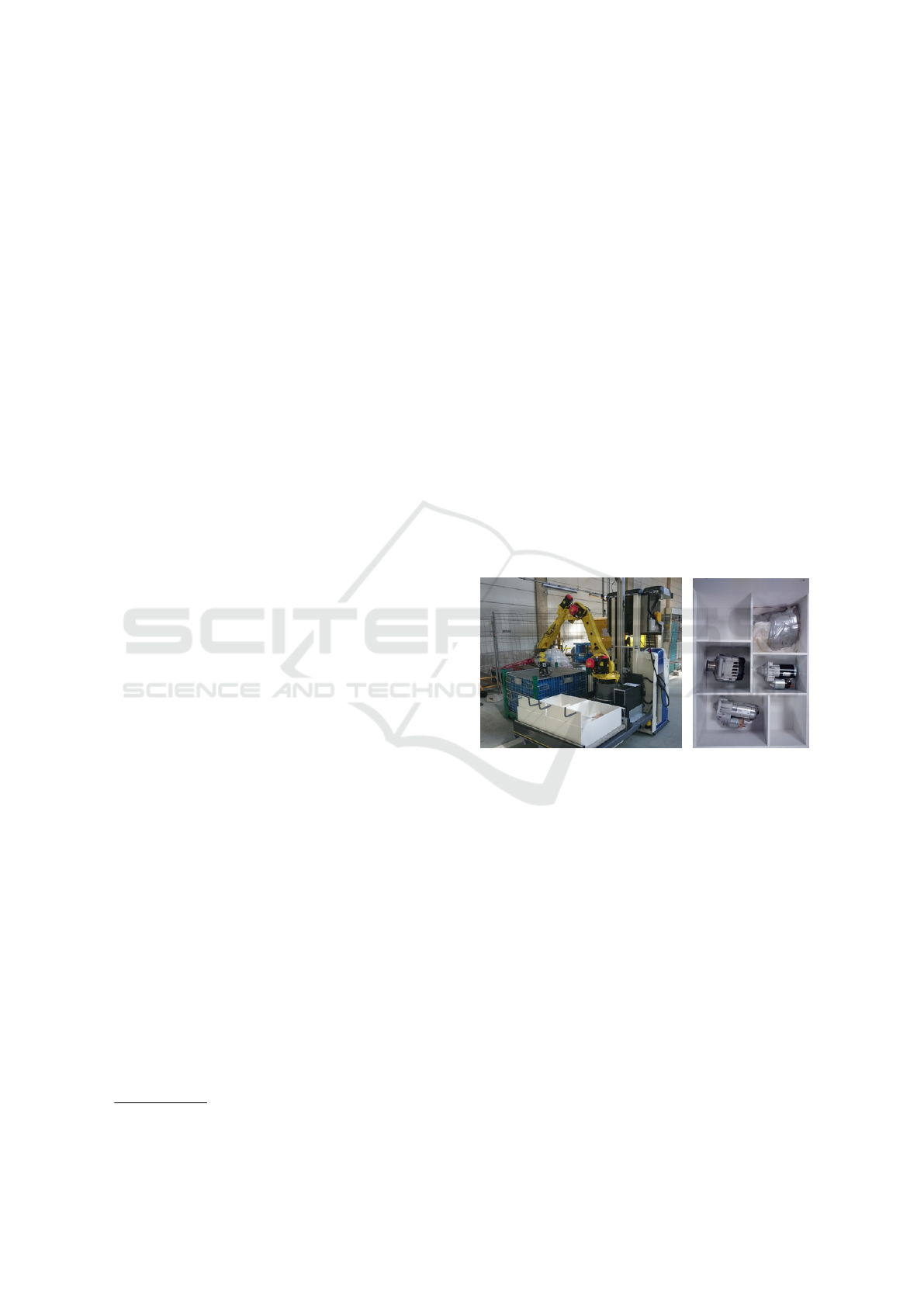
Figure 1: The STAMINA mobile robot (left) manipulating
objects and filling two kitting boxes placed in the front of
the robotic platform. A closeup of a kitting box structure
(right).
will be used for that specific car. Thus, each box con-
tains different parts. This is where the STAMINA
robotic system—shown in Fig. 1(left)—comes into
the picture. The robot receives information form the
Manufacturing Execution System (MES) about the
parts required for each kitting box, it identifies the re-
quested objects and it places them into specific com-
partments of the kitting box, as shown in Fig. 1(right).
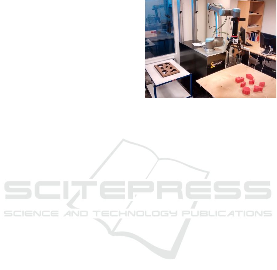
We have replicated the STAMINA scenario, in the
lab using a smaller UR10 robotic arm, 3D printed
parts with complex geometries and also a custom-
made kitting box. The system has no prior knowledge
about the objects or the kitting box, apart from their
coarse initial locations. Each object fits in a specific
compartment of the kitting box. However these corre-
spondences are unknown to the system. Correct cor-
Rofalis, N., Nalpantidis, L., Andersen, N. and Krüger, V.
Vision-based Robotic System for Object Agnostic Placing Operations.
DOI: 10.5220/0005712404650473
In Proceedings of the 11th Joint Conference on Computer Vision, Imaging and Computer Graphics Theory and Applications (VISIGRAPP 2016) - Volume 3: VISAPP, pages 467-475
ISBN: 978-989-758-175-5
Copyright
c
2016 by SCITEPRESS – Science and Technology Publications, Lda. All rights reserved
467

respondences between the objects and the compart-
ments are required before starting manipulating the
former. Afterwards, the robot picks the object—with
no knowledge about suitable grasping poses—moves
to the matching hole, and finally places it in there.
2 RELATED WORK
This work presents a working system that needs to
perform a number of different functions, such as
object detection from visual data, object matching,
grasping and placing of objects. Previous work on
object detection has been conducted using a variety of
methods. (Divvala et al., 2009) conducted an empiri-
cal study on object detection. Using a standard dataset
and top-performing local appearance, they evaluate
numerous sources of context. Context is also used
by (Xiong and Huber, 2010) in order to create seman-
tic 3D models. These 3D models contain information
about the geometry and the identity of a part of a fa-
cility (floors, walls). Using data from a 3D laser scan-
ner (point clouds) they classify planes discovered in
the environment. Also, (Koppula et al., 2011) label
semantically objects in indoor scenes using 3D point
clouds. Their graphical model, contains information,
such as, visual appearance, shape, geometric relation-
ships. Differently, we are focusing on industrial ob-
jects.
Another object segmentation method by (Nalpan-
tidis et al., 2012) takes advantage of camera move-
ment; performs edge extraction, polar domain repre-
sentation and integrates them over time. Furthermore,
(Fisher and Hanrahan, 2010) developed an algorithm
that can search a scene and distinguish the asked ob-
ject among the others using geometric cues and spa-
tial relationships. Robust real-time object detection
performed by (Viola and Jones, 2001). They intro-
duced a new image representation that allows rapid
feature detection. Also, their learning algorithm is ca-
pable of detecting a number of crucial features on the
images. Their developed algorithm utilises classifiers
that allow quick and robust background extraction, in
order to focus only on image’s part that contains use-
ful for detection features. Another comparative study
about object detection performed by (Sapna Varshney
et al., 2009). They tested different techniques for im-
age segmentation, such as, edge-based, KMeans clus-
tering, thresholding and region-based. Moreover, us-
ing still images, 3D geometric properties can be de-
rived that will allow easier object detection. (Saxena
et al., 2008) estimate depth from a single still image.
They collect monocular images of outdoor environ-
ment alongside with their corresponding depth maps
(ground truth). Applying supervised machine learn-
ing make an estimation of the depth using still im-
ages. On the contrary, in our work there is no prior
knowledge about the objects.
Object matching in two-dimensional images has
been an important issue in computer vision. Work on
object matching similar to the task the current work
attempts to deal with, is the one presented by (Flusser,
1995). This article present the work on matching two
sets of objects, which may differ in translation, rota-
tion and scale. Aiming in accurate matching, local
information (set of invariant features) and object-to-
object distances on the plane are used. Also, match-
ing likelihood coefficients are introduced to indicate
the correspondence between objects. Work on shape
matching and later object recognition was conducted
by (Berg et al., 2005). Using geometric blur point
descriptors and geometric distortion between the cor-
responding feature points, they calculate the aligning
transformation that results in solid shape matching.
Object matching using locally affine-invariant con-
strain conducted by (Li et al., 2010). The idea behind
their work is that each point can be represented by an
affine combination of its neighbour points. (Jiang and
Yu, 2009) proposed a linear formulation that finds fea-
ture points correspondences and the geometric trans-
formations.
Regarding grasping objects, an extended body of
work has been performed. (Rietzler et al., 2013) pre-
sented a grasping method that takes into considera-
tion constrains established by both local shape and
acted by the object. A combination of human in-
put and automatic grasping technique is introduced
by (Ciocarlie and Allen, 2008). They created a sys-
tem that is equipped with an automated grasp planner
capable of shaping the artificial hand accordingly to
the shape of the object that is aiming to grasp, let-
ting the user to complete successfully the task. An
other approach is introduced by (Miller et al., 2003).
They simplified grasping task by simplifying the ob-
jects and modelling them into sets of primitive shapes,
such as cylinders, boxes, spheres. As a result, sim-
pler objects and sets of rules allow the calculation of
grasping poses. Grasping objects in conjunction with
supervised machine learning introduced by (Saxena
et al., 2006). Their learning algorithm does not re-
quire 3D model of the object. The training is per-
formed on synthetic images set. In addition, (Detry
et al., 2012) proposed a grasping method that utilizes
a set of grasping examples and tries to match the cur-
rent view with them or with a part of them. In our
work no prior knowledge is available for any of the
objects, so training or comparing with a set of prede-
fined grasping poses is not possible.
VISAPP 2016 - International Conference on Computer Vision Theory and Applications
468
The work of (Hsiao et al., 2009) introduced a
method for grasping objects using optical proxim-
ity sensors, located inside the fingertips of the grip-
per. This system could be supplementary to exist-
ing grasping algorithms. A combination of different
object representations is conducted by (Brook et al.,
2011). Instead of using one representation of the ob-
ject in order to plan the grasping, all the available
representations are combined and the extracted infor-
mation is used to plan grasping accordingly. More-
over, efficient grasping was presented by (Jiang et al.,
2011). Their technique derives information from
RGB-D images (normal RGB images that also con-
tain depth information). Firstly, space not suitable
for grasping is excluded and the remaining is tested
with advanced features until the best one is detected.
Inspired by human actions is the work conducted by
(Dogar and Srinivasa, 2011). They used a library of
actions inspired of actions that humans perform while
grasping objects in cluttered environment (i.e. rear-
ranging clutters).
Regarding object placing, (Schuster et al., 2010)
developed an algorithm to detect clutter-free planes
were objects can safely be placed. Orientation is also
essential, thus (Fu et al., 2008) based on geometrical
features of the objects they reduced the dimensional-
ity of the orientation to a set of possible orientations
that are suitable for an object. Their algorithm fo-
cused on deriving the upright orientation for proper
placing on flat areas. Also, (Saxena et al., 2009),
focused on deriving object orientation. Their algo-
rithm could extract object’s orientation from a sin-
gle image. (Glover et al., 2012) calculate the pose of
an object using sets of local features on partial point
clouds. Additionally, (Kouskouridas and Gasteratos,
2012) proposed a method that takes into account both
geometrical and appearance based characteristics in
order to extract reliable 3D pose of an object. Inter-
action between human and robot that places objects
was introduced by (Edsinger and Kemp, 2006). The
human passes an object to the robot that afterwards
places it on a shelf. Placing task utilizes force control
that leads to a gentle execution release on the shelf.
(Toussaint et al., 2010) integrated planning, control,
reasoning for placing objects located on flat surfaces
into stacks.
3 DEVELOPED SYSTEM
The complete system developed in a lab environment
comprises of a Universal Robots UR10 robotic arm, a
Robotiq 3-finger adaptive robot gripper, and a Prime-
sense Carmine short range sensor. The Carmine sen-
Figure 2: Complete lab setup. The 7 considered objects
can be seen at the lower-right part of the picture, while the
kitting box on the left.
sor is located on the arm and before the gripper in an
eye-in-hand configuration. The lab setup of the inte-
grated system can be seen in Fig. 2.
In order to place any object into its matching com-
partment, we need to initially perform object detec-
tion both for the objects and for the compartments of
the kitting box. Then, we need to perform matching
between the two of them. However, the two images,
of the kitting box and of the objects, do not depict the
same physical entities and as a result matching is not
straightforward. Actually, the only common charac-
teristic between the holes and the objects is their outer
shape. Hence, the contours of all objects and holes are
extracted and compared. Next, matching is performed
on the contours. These correspondences between ob-
jects and holes are used as an input for the final step,
planning and performing grasping and placing. An
overview of the structure and flow of the developed
algorithm is shown in Fig. 3.
3.1 Visual Detection and Matching
The used RGB-D sensor generates depth images,
which are not sensitive to shading and changes of the
lighting conditions as RGB images are. Hence, as
a start, we use the depth images to perform robust
edge detection. Even without any preprocessing of
the depth images the edges of the objects were quite
clear, containing however some noise, as can bee seen
in Fig. 4(left). We then applied a dilatation-erosion
technique to remove most of the noise. Nevertheless,
some limited noise still existed after this “cleaning”
step, as shown in Fig. 4(right). There was just a slight
improvement.
The next step is to distinguish the objects and the
holes in the edge images. Examining the input images
Vision-based Robotic System for Object Agnostic Placing Operations
469
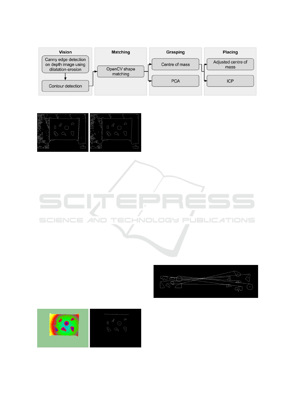
Figure 3: Algorithm flow chart.
Figure 4: Edges in a typical image detected by Canny (left)
and the same edges after applying dilation-erosion (right).
of Fig. 4(right) one can notice that most of the noise
belongs to the supporting plane where the objects or
the placing box are placed. However, this area is of
no interest from our purpose and can be ignored.
Due to the placing of the camera on the gripper,
the latter is always visible in the captured images and
point clouds. In order to get rid of the part of the point
cloud belonging to the gripper itself, any point closer
than 55 cm from the sensor is removed. Furthermore,
all points more than 15 cm farther than the first de-
tected object are removed. as well. As a result, we are
left with a truncated point cloud both for very close
and for very distant objects. Of course, the aforemen-
tioned values were chosen based on the specific geo-
metric characteristics of our lab setup and should be
adapted accordingly in different environments.
Then, the depth image is filtered, so as to keep
only edges belonging to objects present in the filtered
point cloud. Areas where no information about the
point cloud exist (e.g. the homogeneous outer area
of Fig. 5(left)) are also filtered from the depth im-
age. The result as shown in Fig. 5(right) does not
contain much irrelevant information and the objects
Figure 5: The filtered point cloud (left) and the filtered de-
tected edges on the depth image (right).
are clearly depicted.
The next step, after removing noise is to isolate
and group the detected edges in contours. The algo-
rithm by (Suzuki et al., 1985) is used for that pur-
pose as it is implemented in the OpenCV library. All
objects are detected, but as can be seen in the up-
per part of Fig. 5(right), some edges—owed to the
depth discontinuities in the boundaries of the sup-
porting surface—occur some times. The spots in the
middle of each contour are their respective centers of
mass (Fig. 5(right)). One can notice that the spurious
edge in the upper part of the images also gets a center
of mass assigned.
We are using image moments to perform the
matching between the contours belonging to objects
and holes. Moments, in general, are widely used to
describe images or shapes. Direct shape matching
uses Hu invariants to compare shapes. We use this
technique as implemented in OpenCV. The Hu mo-
ments are scale invariant. However, this is not help-
ful when trying to distinguish between similar objects
that are different in size. Therefore, an additional fil-
ter regarding the size of the detected contour area was
added to the matching process. As a result, matching
between object and corresponding holes in the kitting
boxes is established, as can be shown in Fig. 6.
Figure 6: Matched objects and box-holes.
3.2 Grasping & Placing
After matching the objects to the appropriate holes,
the arm grasps and places them accordingly. When
the RGB-D sensor is looking at an object vertically
the precision is better. The positions of the objects are
inferred from their calculated centers of mass. The
arm moves above a randomly selected object to get
VISAPP 2016 - International Conference on Computer Vision Theory and Applications
470
a close vertical view and, as a result, a more precise
estimation of its pose.
As we assume no prior knowledge about the ob-
jects, no predefined grasping poses are known to the
system. Our approach is to grasp the object perpen-
dicular to its principal direction, thus maximizing the
grasping surface. When the RGB-D sensor gets a
more precise view of the object it also calculates its
two-dimensional orientation on the supporting plane.
In order to acquire that information, principal com-
ponent analysis (PCA) is performed on the detected
contour of the observed object and the principal di-
rection is extracted.
After acquiring more precise information about
the center of mass and the orientation of the object,
the arm grasps it and releases it again. In most of the
cases during this initial grasping, the object moves
and rotates a bit. The reason for this is that the ex-
tracted center of mass and orientation are rarely per-
fect, but even if they are, the fingers of the gripper can
slide into an object’s cavity or on a non vertical side.
The result of this is a change of the object’s pose.
Afterwards, a second observation above the object
is performed (using the exact same pose that was uti-
lized to acquire the first measurement) and extracts
the new center of mass. The gripper grasps the object
with the same pose as before. This strategy decreases
the possibility of moving the object once again and
measures the misplacement that occurred after the
first grasping attempt. The measured change of the
position (center of mass misplacement) between the
two grasping attempts will be used later during the
placing of the object.
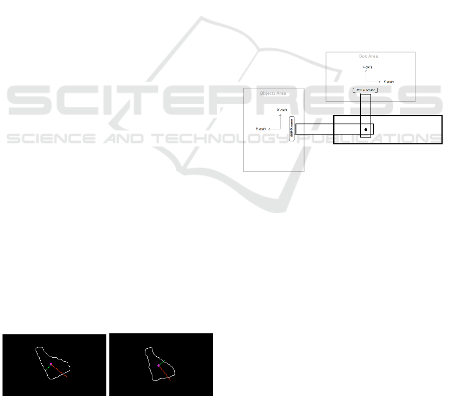
In the following figures (Fig. 7) the output of the
PCA algorithm applied on the detected contours of
an object before and after the first grasping attempt is
displayed. It is visible that one axis (the secondary
one) has opposite direction even though it is the same
object slightly rotated. At that point, this has no ef-
fect due to the fact that PCA is used just once before
grasping the object for the first time, in order to get
the orientation that the gripper will use so to grasp the
object. Thus, the change on the orientation before and
after grasping for the first time does not matter at that
stage.
Figure 7: Principle Components Analysis (PCA) performed
before (left) and after (right) the first grasping attempt.
When the picking task is completed and the mis-
placement after the first grasping is known, the arm
moves to the corresponding box-hole to place the ob-
ject. What is important to know for that step is the
precise placement position and orientation of the cor-
responding hole.
The arm moves directly above the matched box-
hole (using the center of mass of the detected con-
tour). This step is necessary in order to get a new
more precise observation of the hole. The newly de-
tected contour of the box-hole is used so to extract a
precise center of mass at this point. Moreover, the cal-
culated misplacement after the first grasping is taken
into consideration when the placing process is per-
formed. An important note, is the fact that the axes
while grasping and placing are not the same (Fig. 8).
There is a rotation of -90
◦
(clockwise), hence the esti-
mated misplacement on the X-axis should be consid-
ered in order to make a correction on the Y-axis during
placing. Accordingly, the estimated misplacement on
the Y-axis should be considered when placing on the
X-axis.
Figure 8: Comparison between camera axis during grasping
and placing task.
As it is already stated, precision is highly impor-
tant during placing. The gap between an object and
the corresponding box-hole, for our tested objects and
kitting box, is small (less than 5 mm). Apart from
the precise position, the exact orientation of the box-
hole needs to be also calculated. We refine the ini-
tial coarse orientation using the Iterative Closest Point
(ICP) method.
The ICP algorithm aligns the captured point
clouds of the object and of the hole. The object point
cloud is the source and box-hole point cloud the ref-
erence. Both of them were filtered on all three axis to
reduce the processed data.
However, the two point clouds do not have parts in
common (Fig. 9) and even though they look similar to
each other, they are in practice complementary. Thus,
ICP can not be applied directly on them.
As solution to the this problem, artificial point
Vision-based Robotic System for Object Agnostic Placing Operations
471
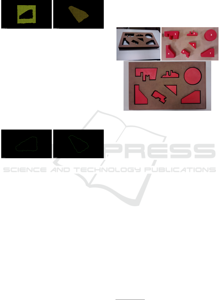
Figure 9: The box-hole (left) and the object (right) point
clouds input for the ICP algorithm.
clouds are generated in order to provide input to ICP.
The contour of both the object and the box-hole are
similar, thus the new point clouds are generated using
the points of the detected contours in both cases. This
results in clean point clouds with no noise, where the
detected contours are clearly visible (Fig. 10). Ap-
plying ICP on these new point clouds provides good
results concerning rotation. The output translation is
not taken into consideration, only the rotation trans-
formation is necessary. It is important to note that
before applying ICP no transformation is applied to
the source point cloud (object). Thus, there might be
cases in which ICP “locks” in local minima, provid-
ing wrong angle.
Figure 10: The box-hole (left) and the object (right) artifi-
cial point clouds input for the ICP algorithm.
4 SYSTEM EVALUATION
The developed system has been tested in order to
study its performance and explore its limitations. All
following tests were performed on a single placing
kitting box (Fig. 11(top left)) and a specific set of
seven objects (Fig. 11(top right)). The placing box
contains holes that are shaped exactly as the objects,
the only difference being that the holes are slightly
larger allowing a 4-5 mm gap around placed objects
(Fig. 11(bottom)). The set of objects was chosen and
designed in order to ensure diversity and increasing
shape complexity. Two of the objects have simple
shapes (objects 3 and 6 in Fig. 11(top right)), two are
slightly more complex but similar to each other (ob-
jects 4 and 7 in Fig. 11(top right)), and three have fine
details and complicated geometry (objects 1, 2 and 5
in Fig. 11(top right)). Even if we consider the cho-
sen set of objects challenging—especially since the
kitting box compartments are tight— it is dangerous,
if not completely mistaken, to consider it as indica-
tive of the vast majority of industrial parts handled
by robots. However, this work aspires to show that
within some limits a robotic system can be flexible
enough to handle diverse sets of previously unknown
objects.
Figure 11: The objects (top right) placed (bottom) into the
placing box (top left).
The placing box and the objects are located in dif-
ferent positions in the working space and with ran-
dom orientations. We performed 50 iterations of fill-
ing the kitting box with the whole set, resulting in a
total of 350 individual matching, picking and plac-
ing sequences. Notes were taken during each attempt
in order to extract useful information concerning the
system and its performance. In the rest of this work
we will refer to the objects with their assigned num-
bers, as shown in Fig. 11(top right).
The operation of the developed system can be
seen in a captured video showing the placing of the
whole set of objects once
2
. During the tests, both
the holes of the placing box and the objects were
always detected correctly. This fact ensures a good
starting point for the performance of the matching
algorithm. Out of the 350 matching attempts that
were performed, only 16 resulted in mismatches, i.e.
we achieved 95.43% success rate. Out of these 16
mismatches, 9 were on object No.2, 5 were on ob-
ject No.5, one on No.1, and another one on No.7.
This means that more than half (56.25%) of the mis-
matches were on object No.2 and almost one third
(31.25%) on No.5. Objects No.2 and No.5 were
among the smallest ones, and also are very detailed
around their perimeter. Due to that level of detail
and their small size, the detected contours were not
always sharp, thus making matching difficult and in
some cases erroneous. These results are summarized
in Table 1.
2
https://youtu.be/UlqnO0-YZQw
VISAPP 2016 - International Conference on Computer Vision Theory and Applications
472
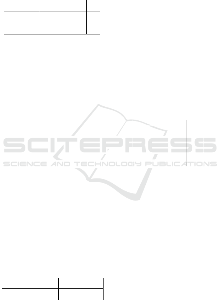
Table 1: Matching algorithm performance.
Correct matches
Wrong matches
Total
Object Occurences
334
No.2 9
350
No.5 5
No.1 1
No.7 1
To perform the picking and placing tasks, an exter-
nal path planner was employed (we used the MoveIt!
library) for planning the path of the robot arm avoid-
ing collisions. However, in certain cases the path
planner was failing to converge or to provide a valid
path. More precisely, out of a total of 350 attempts
the planner failed to provide a satisfactory path 72
times. This means that only 79.43% of all attempts
were accomplished without any planner relevant er-
ror. While we have marked those attempts as failures,
they are not directly concerned with our developed
pipeline. Such problems could be avoided by trying
alternative path planners or by properly parametrizing
them. However, this work falls outside our scope and
we consider it as a possible future extension.
When assessing the overall performance of the
system, we do not consider the failures caused by
the planner. Only errors directly related to our de-
veloped systems are taken into account. Furthermore,
only objects that are fully into the appropriate box-
hole are measured as successful placings. Objects
that are partially into the hole (e.g. having one cor-
ner outside the hole) are considered as unsuccess-
ful attempts. Under these assumptions, the overall
performance measured is 76.26%, or 212 successful
placing attempts out of 278. When excluding the at-
tempts where matching was erroneous—thus evalu-
ating the pick and place modules alone— we get a
better success rate of 80.92%, or 212 successful plac-
ing attempts out of 262. Erroneously calculated plac-
ing angle was the reason for not precise object place-
ment in 9 attempts. The wrong angle is due to the fact
that ICP “locked” in a local minimum and calculated
wrong rotation for the object. In more than half of
these misplacements (5 out of 9, or 55.56%) the in-
volved object was No.7, twice No.6, and also twice
No.4. These results are summarized in Table 2.
Furthermore, apart from angle miscalculation,
other misplacements occurred due to not precise po-
Table 2: Overall system performance.
Assessed Successful Total Success
Modules attempts attempts rate (%)
Match, Grasp, Place 212 278 76.26
Grasp, Place 212 262 80.92
sitioning. There were 41 attempts that did not end up
with a nice placement and in all cases the error was
less than 3 mm. Out of 41 misplacements 13 were
about object No.7 (31.71%). This object can be char-
acterized as tricky regarding grasping. Moreover, 8
out of 41 attempts were about object No.2 (19.52%).
As it was mentioned regarding mismatching, object
No.2 has a high level of detail and small size. This
makes it difficult to extract rigid and detailed con-
tours, and as a consequence the center of mass could
not be precise enough for a good placing. It can be
observed that more than half of the misplacements
(51.23%) due to not precise position happened on ob-
jects No.7 and No.2.It is worth mentioning that object
No.3 (the cylinder) was never misplaced. Of course,
the placement angle in this case is not an issue but also
the lack of details and the relatively big size of it (it
was among the biggest objects) led to clear contours
and as a result higher precision for the calculated cen-
ter of mass. These results are summarized in Table 3.
Table 3: Object misplacement analysis.
Object Misplacements %
No.7 13 31.71
No.2 8 19.52
No.6 6 14.63
No.1 5 12.2
No.4 5 12.2
No.5 4 9.76
Total 41 100
5 DISCUSSION AND
CONCLUSIONS
Our aim was to test the ability of an industrial robotic
system to manipulate unknown objects within an un-
known environment. The developed system indeed
fulfilled its purpose, by placing objects using a robotic
arm and exploiting computer vision, with an accept-
able success rate. Even though there was no prior
knowledge about the objects, it detected and matched
them to the corresponding box-holes with a good suc-
cess rate.
Regarding edge detection, Canny edge detection
algorithm was used due to its robustness throughout
the development of the robotic system. Applying it
on the depth image instead of the RGB one, was a
decision made by keeping in mind that the system
is aiming industry, thus robustness here also, is ex-
cessively important. Shape matching using OpenCV
performed well, resulting in good success rate during
testing. Apart from difficulties related to the match-
Vision-based Robotic System for Object Agnostic Placing Operations
473

ing task, the low ability of the used RGB-D sensor
to distinguish all the details around objects’ contour
led occasionally to not precise enough estimation of
the center of mass, hence increased misplacements.
Also misplacements occurred due to erroneous plac-
ing orientation that derive from the drawback of the
ICP algorithm to “lock” occasionally in local minima.
Nonetheless, ICP performed better than the tested
sole PCA algorithm. On the other hand, PCA per-
formed well in the grasping module. It provided in-
formation that allowed picking objects even though
no prior knowledge about them was available. How-
ever, the designed objects proved to be relative small
for the bulky gripper that was used, hence grasping in
some occasions was problematic. Finally, it is notable
the fact that the planner is responsible for several fail-
ures and cancellations during the testing process. It
does not affect the results because it did not consid-
ered as failure of the developed algorithm but it is an
important issue that lowers the robustness of the sys-
tem.
In order to improve the developed system there are
changes that could be applied to all its different mod-
ules. In order to deal with the issues owed to the plan-
ner, one could perform checks on the estimated tra-
jectories before executing them. These checks could
either consider the time that is needed for the trajec-
tory to be executed (too short or too long times should
be rejected), or on the total distance that the trajectory
indicates. Also, carefully applying constrains to each
joint separately can improve the situation.
Larger objects while using the current gripper will
make grasping easier and more solid. In case the sys-
tem has to manipulate small objects, a replacement
of the gripper with one designed for smaller objects
would definitely help. Of course a more generic so-
lution would be the use of a tool changer. Informa-
tion extracted by the RGB-D sensor provide enough
evidence for each object’s size in order to decide re-
garding the proper gripper that is more suitable. Thus
switching end effector during the process will con-
clude in a more robust system. One gripper can not
be perfect for all objects.
Regarding grasping, an additional algorithm that
automatically generates grasping poses that lead to
solid grasping can make much of a difference. This
additional algorithm is necessary, in order to have a
system which does not require prior knowledge. Also,
an extension of our double-grasping strategy could be
an iterative process of grasping the object and releas-
ing it multiple times until the misplacement is within
a threshold. This will increase the possibilities for not
moving the object during the last grasping attempt be-
fore it moves above the box-hole.
Placing can become more robust using force
sensing—the so called guarded motions. Even if the
placing pose is not perfectly calculated, the arm could
slide the object around the estimated position and us-
ing different orientation that are close to the estimated
one while having access to the forces that the robot
senses. When these forces are minimized the object
has the proper pose for placing. However, this would
require a solid placing box that is rigidly attached on
the working plane. Furthermore, placing could be im-
proved by using visual servoing (vision based robot
control). Such solutions would transform the devel-
oped system from an open control loop to a closed
loop one.
Lastly, a more precise sensor will definitely boost
the accuracy of the center of mass that is calculated
for both objects and holes. Taking into account the
fact that this system is aiming industry, testing also
other sensors is a necessity. Parts that are used in in-
dustry are mostly metallic, hence reflective. This will
decrease significantly the applicability of the current
sensor.
ACKNOWLEDGEMENTS
This work has been supported by the European Com-
mission through the research project “Sustainable
and Reliable Robotics for Part Handling in Manu-
facturing Automation (STAMINA)” (FP7-ICT-2013-
10-610917) and by the Innovation Fund Denmark
through the research project “Mini-Picker”.
REFERENCES
Berg, A. C., Berg, T. L., and Malik, J. (2005). Shape match-
ing and object recognition using low distortion corre-
spondences. In Computer Vision and Pattern Recogni-
tion, 2005. CVPR 2005. IEEE Computer Society Con-
ference on, volume 1, pages 26–33. IEEE.
Brook, P., Ciocarlie, M., and Hsiao, K. (2011). Collabo-
rative grasp planning with multiple object represen-
tations. In Robotics and Automation (ICRA), 2011
IEEE International Conference on, pages 2851–2858.
IEEE.
Ciocarlie, M. T. and Allen, P. K. (2008). On-line interactive
dexterous grasping. In Haptics: Perception, Devices
and Scenarios, pages 104–113. Springer.
Detry, R., Ek, C. H., Madry, M., Piater, J., and Kragic, D.
(2012). Generalizing grasps across partly similar ob-
jects. In IEEE International Conference on Robotics
and Automation.
Divvala, S. K., Hoiem, D., Hays, J. H., Efros, A., Hebert,
M., et al. (2009). An empirical study of context in ob-
ject detection. In Computer Vision and Pattern Recog-
VISAPP 2016 - International Conference on Computer Vision Theory and Applications
474

nition, 2009. CVPR 2009. IEEE Conference on, pages
1271–1278. IEEE.
Dogar, M. and Srinivasa, S. (2011). A framework for push-
grasping in clutter. Robotics: Science and Systems
VII.
Edsinger, A. and Kemp, C. C. (2006). Manipulation in hu-
man environments. In Humanoid Robots, 2006 6th
IEEE-RAS International Conference on, pages 102–
109. IEEE.
Fisher, M. and Hanrahan, P. (2010). Context-based search
for 3d models. In ACM Transactions on Graphics
(TOG), volume 29, page 182. ACM.
Flusser, J. (1995). Object matching by means of matching
likelihood coefficients. Pattern Recognition Letters,
16(9):893–900.
Fu, H., Cohen-Or, D., Dror, G., and Sheffer, A. (2008).
Upright orientation of man-made objects. In ACM
transactions on graphics (TOG), volume 27, page 42.
ACM.
Glover, J., Bradski, G., and Rusu, R. B. (2012). Monte carlo
pose estimation with quaternion kernels and the bing-
ham distribution. In Robotics: science and systems,
volume 7, page 97.
Hsiao, K., Nangeroni, P., Huber, M., Saxena, A., and Ng,
A. Y. (2009). Reactive grasping using optical prox-
imity sensors. In Robotics and Automation, 2009.
ICRA’09. IEEE International Conference on, pages
2098–2105. IEEE.
Jiang, H. and Yu, S. X. (2009). Linear solution to scale
and rotation invariant object matching. In Computer
Vision and Pattern Recognition, 2009. CVPR 2009.
IEEE Conference on, pages 2474–2481. IEEE.
Jiang, Y., Moseson, S., and Saxena, A. (2011). Efficient
grasping from rgbd images: Learning using a new
rectangle representation. In Robotics and Automa-
tion (ICRA), 2011 IEEE International Conference on,
pages 3304–3311. IEEE.
Koppula, H. S., Anand, A., Joachims, T., and Saxena, A.
(2011). Semantic labeling of 3d point clouds for in-
door scenes. In Advances in Neural Information Pro-
cessing Systems, pages 244–252.
Kouskouridas, R. and Gasteratos, A. (2012). Establishing
low dimensional manifolds for 3d object pose estima-
tion. In Imaging Systems and Techniques (IST), 2012
IEEE International Conference on, pages 425–430.
IEEE.
Li, H., Kim, E., Huang, X., and He, L. (2010). Object
matching with a locally affine-invariant constraint. In
Computer Vision and Pattern Recognition (CVPR),
2010 IEEE Conference on, pages 1641–1648. IEEE.
Miller, A. T., Knoop, S., Christensen, H., Allen, P. K.,
et al. (2003). Automatic grasp planning using shape
primitives. In Robotics and Automation, 2003. Pro-
ceedings. ICRA’03. IEEE International Conference
on, volume 2, pages 1824–1829. IEEE.
Nalpantidis, L., Bj
¨
orkman, M., and Kragic, D. (2012). Yes-
yet another object segmentation: Exploiting camera
movement. In Intelligent Robots and Systems (IROS),
2012 IEEE/RSJ International Conference on, pages
2116–2121. IEEE.
Rietzler, A., Detry, R., Kopicki, M., Wyatt, J. L., and Piater,
J. (2013). Inertially-safe grasping of novel objects. In
Cognitive Robotics Systems: Replicating Human Ac-
tions and Activities (Workshop at IROS 2013).
Sapna Varshney, S., Rajpa, N., and Purwar, R. (2009). Com-
parative study of image segmentation techniques and
object matching using segmentation. In Methods and
Models in Computer Science, 2009. ICM2CS 2009.
Proceeding of International Conference on, pages 1–
6. IEEE.
Saxena, A., Chung, S. H., and Ng, A. Y. (2008). 3-d depth
reconstruction from a single still image. International
journal of computer vision, 76(1):53–69.
Saxena, A., Driemeyer, J., Kearns, J., and Ng, A. Y. (2006).
Robotic grasping of novel objects. In Advances in
neural information processing systems, pages 1209–
1216.
Saxena, A., Driemeyer, J., and Ng, A. Y. (2009). Learn-
ing 3-d object orientation from images. In Robotics
and Automation, 2009. ICRA’09. IEEE International
Conference on, pages 794–800. IEEE.
Schuster, M. J., Okerman, J., Nguyen, H., Rehg, J. M., and
Kemp, C. C. (2010). Perceiving clutter and surfaces
for object placement in indoor environments. In Hu-
manoid Robots (Humanoids), 2010 10th IEEE-RAS
International Conference on, pages 152–159. IEEE.
Suzuki, S. et al. (1985). Topological structural analy-
sis of digitized binary images by border following.
Computer Vision, Graphics, and Image Processing,
30(1):32–46.
Toussaint, M., Plath, N., Lang, T., and Jetchev, N. (2010).
Integrated motor control, planning, grasping and high-
level reasoning in a blocks world using probabilistic
inference. In Robotics and Automation (ICRA), 2010
IEEE International Conference on, pages 385–391.
IEEE.
Viola, P. and Jones, M. (2001). Robust real-time object
detection. International Journal of Computer Vision,
4:51–52.
Xiong, X. and Huber, D. (2010). Using context to create se-
mantic 3d models of indoor environments. In BMVC,
pages 1–11.
Vision-based Robotic System for Object Agnostic Placing Operations
475
