
Branch-and-Bound Optimization of a Multiagent System for Flow
Production using Model Checking
Stefan Edelkamp and Christoph Greulich
University of Bremen, Institute for Artificial Intelligence, Am Fallturm 1, 28359 Bremen, Germany
Keywords:
Multiagent Systems, Model Checking, Optimization, Branch-and-Bound, Autonomous Production.
Abstract:
In this paper we propose the application of a model checker to evaluate a multiagent system that controls
the industrial production of autonomous products. As the flow of material is asynchronous at each station,
queuing effects arise as long as buffers provide waiting room. Besides validating the design of the system,
the core objective of this work is to find plans that optimize the throughput of the system. Instead of mapping
the multiagent system directly to the model checker, we model the production line as a set of communicating
processes, with the movement of items modeled as communication channels. Experiments shows that the
model checker is able to analyze the movements of autonomous products for the model, subject to the partial
ordering of the product parts. It derives valid and optimized plans with several thousands of steps using
constraint branch-and-bound.
1 INTRODUCTION
The ongoing transformation of production indus-
tries causes a paradigm shift in manufacturing pro-
cesses towards new technologies and innovative con-
cepts, called cyber, smart, digital or connected fac-
tory (Bracht et al., 2011). The sector is entering its
fourth revolution, characterized by a merging of com-
puter networks and factory machines. At each link
in the production and supply chains, tools and work-
stations communicate constantly via the Internet and
local networks. Machines, systems, and products ex-
change information both among themselves and with
the outside world.
Flow Production Systems are installed for prod-
ucts that are produced in high quantities. By opti-
mizing the flow of production, manufacturers hope to
speed up production at a lower cost, and in a more en-
vironmentally sound way. In manufacturing practice
there are not only series flow lines (with stations ar-
ranged one behind the other), but also more complex
networks of stations at which assembly operations are
performed (assembly lines). The considerable dif-
ference from flow lines, which can be analyzed by
known methods, is that a number of required compo-
nents are brought together to form a single unit for
further processing at the assembly stations. An as-
sembly operation can begin only if all required parts
are available.
Performance Analysis of flow production systems
is generally needed during the planning phase regard-
ing the system design, when the decision for a con-
crete configuration of such a system has to be made.
The planning problem arises, e.g., with the introduc-
tion of a new model or the installation of a new manu-
facturing plant. Because of the investments involved,
an optimization problem arises. The expenditure for
new machines, for buffer or handling equipment, and
the holding costs for the expected work-in-process
face revenues from sold products. The performance
of a concrete configuration is characterized by the
throughput, i.e., the number of items that are pro-
duced per time unit. Other performance measures are
the expected work in process or the idle times of ma-
chines or workers.
In this paper we consider assembly-line networks
with stations, which are represented as a directed
graph. Between any two successive nodes in the net-
work, we assume a buffer of finite capacity. In the
buffers between stations and other network elements,
work pieces are stored, waiting for service. At assem-
bly stations, service is given to work pieces. Travel
time is measured and overall time is to be optimized.
Our running case study is the so called Z2, a phys-
ical monorail system for the assembling of tail-lights.
Unlike most production systems, Z2 employs agent
technology to represent autonomous products and as-
sembly stations. The techniques developed, however,
will be applicable to most flow production systems.
We formalize the production floor as a system of com-
Edelkamp, S. and Greulich, C.
Branch-and-Bound Optimization of a Multiagent System for Flow Production using Model Checking.
DOI: 10.5220/0005705100270037
In Proceedings of the 8th International Conference on Agents and Artificial Intelligence (ICAART 2016) - Volume 1, pages 27-37
ISBN: 978-989-758-172-4
Copyright
c
2016 by SCITEPRESS – Science and Technology Publications, Lda. All rights reserved
27

municating processes and apply the state-of-the-art
model checker Spin (Holzmann, 2004) for analyzing
its behavior. Using optimization mechanisms imple-
mented on top of Spin, additional to the verification
of the correctness of the model, we exploit its explo-
ration process for optimization of production flow.
For the optimization Via Model Checking we use
many new language features from the latest version
of the Spin model checker including loops and na-
tive c-code verification. The main contribution of
this text, however, is general cost-optimization via
branch-and-bound. The optimization approach orig-
inally invented for Spin was designed for state space
trees (Ruys and Brinksma, 1998; Ruys, 2003), while
the proposed new approach also supports state space
graphs, crucially reducing the running time and mem-
ory consumption of the algorithm, rendering other-
wise intractable models to become analyzable.
The paper is structured as follows. First, we con-
sider related work on agent-based industrial (flow)
production, on model checking multiagent systems
(MASs), and on planning via model checking. Next,
we introduce the industrial case study, and its mod-
eling as well as its simulation as an MAS. The sim-
ulator is used to measure the increments of the cost
function to be optimized. Then, we turn to the intri-
cacies of the Promela model specification and the pa-
rameterization of Spin, as well as to the novel branch-
and-bound optimization scheme. In the experiments
we validate the conciseness and effectiveness of the
model and the taken approach.
2 RELATED WORK
Especially in open, unpredictable, dynamic, and com-
plex environments, MASs are applied to determine
adequate solutions for transport problems. For ex-
ample, agent-based commercial systems are used
within the planning and control of industrial pro-
cesses (Dorer and Calisti, 2005; Himoff et al., 2006),
as well as within other areas of logistics (Fischer et al.,
1996; B
¨
urckert et al., 2000). A comprehensive survey
is provided by (Parragh et al., 2008).
Flow line analysis is often done with queuing the-
ory (Manitz, 2008; Burman, 1995). Pioneering work
in analyzing assembly queuing systems with synchro-
nization constraints analyzes assembly-like queues
with unlimited buffer capacities (Harrison, 1973). It
shows that the time an item has to wait for synchro-
nization may grow without bound, while limitation of
the number of items in the system works as a control
mechanism and ensures stability. Work on assembly-
like queues with finite buffers all assume exponen-
tial service times (Bhat, 1986; Lipper and Sengupta,
1986; Hopp and Simon, 1989).
2.1 Model Checking Multiagent
Systems
Model checking production flow is rare. Timed au-
tomata were used for simulating material flow in agri-
cultural production (Helias et al., 2008). There are,
however, numerous attempts to apply model checking
to validate the work of MASs.
The LORA framework (Wooldridge, 2000;
Wooldridge, 2002) uses labeled transition and Kripke
systems for characterizing the behavior of the agents
(their belief, their desire and their intention), and tem-
poral logics for expressing their interplay, as well as
for the progression of knowledge. Alternatives con-
sider an MAS as a game, in which agents –either in
separation or cooperatively– optimize their individual
outcome (Saffidine, 2014). Communication between
the agents is available via writing to and reading from
channels, or via common access to shared variables.
Other formalization approaches include work in the
context of the MCMAS tool by Lomuscio
1
. Recently,
there has been some approaches to formalize MASs
as planning problems (Nissim and Brafman, 2013).
2.2 Planning and Model Checking
Since the origin of the term artificial intelligence, the
automated generation of plans for a given task has
been seen as an integral part of problem solving in
a computer. In action planning (Nau et al., 2004),
we are confronted with the descriptions of the initial
state, the goal (states) and the available actions. Based
on these we want to find a plan containing as few ac-
tions as possible (in case of unit-cost actions, or if no
costs are specified at all) or with the lowest possible
total cost (in case of general action costs).
The process of fully-automated property valida-
tion and correctness verification is referred to as
model checking (Clarke et al., 2000). Given a formal
model of a system M and a property specification φ
in some form of temporal logic like LTL (Gerth et al.,
1995), the task is to validate, whether or not the spec-
ification is satisfied in the model, M |= φ. If not, a
model checker usually returns a counterexample trace
as a witness for the falsification of the property.
Planning and model checking have much in com-
mon (Giunchiglia and Traverso, 1999; Cimatti et al.,
1997). Both rely on the exploration of a potentially
large state space of system states. Usually, model
1
http://vas.doc.ic.ac.uk/software/mcmas/
ICAART 2016 - 8th International Conference on Agents and Artificial Intelligence
28
checkers only search for the existence of specifica-
tion errors in the model, while planners search for
a short path from the initial state to one of the goal
states. Nonetheless, there is rising interest in planners
that prove insolvability (Hoffmann et al., 2014), and
in model checkers to produce minimal counterexam-
ples (Edelkamp and Sulewski, 2008).
In terms of leveraging state space search, over the
last decades there has been much cross-fertilization
between the fields. For example, based on Sat-
plan (Kautz and Selman, 1996) bounded model check-
ers exploit SAT and SMT representations (Biere et al.,
1999; Armando et al., 2006) of the system to be
verified, while directed model checkers (Edelkamp
et al., 2001; Kupferschmid et al., 2006) exploit pan-
ning heuristics to improve the exploration for falsifi-
cation; partial-order reduction (Valmari, 1991; Gode-
froid, 1991) and symmetry detection (Fox and Long,
1999; Lluch-Lafuente, 2003) limit the number of suc-
cessor states, while symbolic planners (Cimatti et al.,
1998; Jensen et al., 2001; Edelkamp and Reffel, 1998)
apply functional data structures like BDDs to repre-
sent sets of states succinctly.
3 CASE STUDY: Z2
One of the few successful real-world implementations
of a multiagent flow production is the so called Z2
production floor unit (Ganji et al., 2010; Morales
Kluge et al., 2010). The Z2 unit consists of six work-
stations where human workers assemble parts of au-
tomotive tail-lights. The system allows production of
certain product variations and reacts dynamically to
any change in the current order situation, e.g., a de-
crease or an increase in the number of orders of a cer-
tain variant. As individual production steps are per-
formed at the different stations, all stations are in-
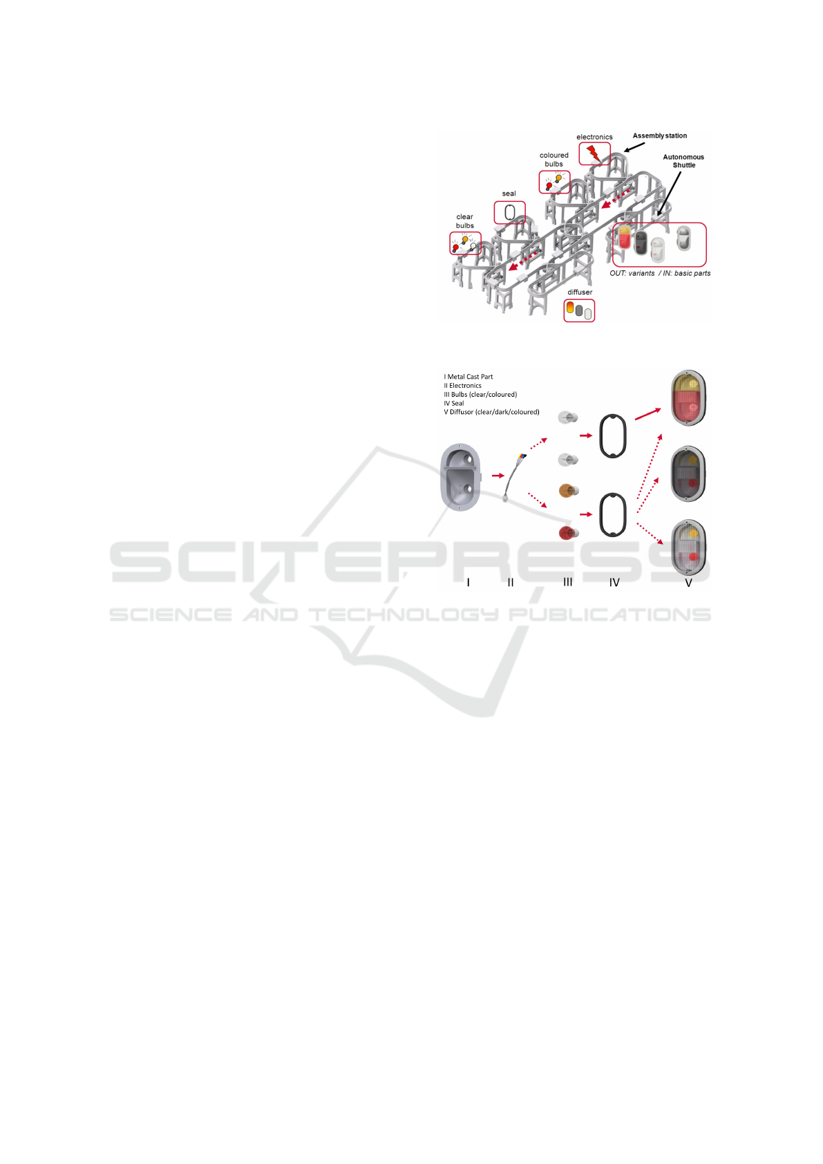
terconnected by a monorail transport system. The
structure of the transport system is shown in Fig-
ure 1. On the rails, autonomously moving shuttles
carry the products from one station to another, de-
pending on the products’ requirements. The monorail
system has multiple switches which allow the shut-
tles to enter, leave or pass workstations and the cen-
tral hubs. The goods transported by the shuttles are
also autonomous, which means that each product de-
cides on its own which variant to become and which
station to visit. This way, a decentralized control of
the production system is possible.
The modular system consists of six different
workstations, each is operated manually by a human
worker and dedicated to one specific production step.
At production steps III and V, different parts can be
Figure 1: Assembly scenario for tail-lights (Morales Kluge
et al., 2010).
Figure 2: Assembly states of tail lights.(Ganji et al., 2010).
used to assemble different variants of the tail-lights
as illustrated in Fig. 2. At the first station, the ba-
sic metal-cast parts enter the monorail on a dedicated
shuttle. The monorail connects all stations, each sta-
tion is assigned to one specific task, such as adding
bulbs or electronics. Each tail-light is transported
from station to station until it is assembled com-
pletely.
From the given case study, we derive a more gen-
eral notation of flow production for an assembly-line
network. System progress is non-deterministic and
asynchronous, while the progress of time is moni-
tored.
Definition 1 (Flow Production). A flow production
floor is a 6-tuple F = (A, E, G,≺, S, Q) where
• A is a set of all possible assembling actions
• P is a set of n products; each P
i
∈ P, i ∈ {1, . . . , n},
is a set of assembling actions, i.e., P
i
⊆ A
• G = (V, E, w, s,t) is a graph with start node s, goal
node t, and weight function w : E → IR
≥0
• ≺ = (≺
1
, . . . , ≺
n
) is a vector of assembling plans
with each ≺
i
⊆ A × A, i ∈ {1, . . . , n}, being a par-
Branch-and-Bound Optimization of a Multiagent System for Flow Production using Model Checking
29

tial order
• S ⊆ E is the set of assembling stations induced by
a labeling ρ : E → A ∪
/
0, i.e., S = {e ∈ E | ρ(e) 6=
/
0}
• Q is a set of (FIFO) queues of finite size |Q| < ∞
together with a labeling ψ : E → Q
Products P
i
, i ∈ {1, . . . , n}, travel through the net-
work G, meeting their assembling plans/order ≺
i
⊆
A × A of the assembling actions A. For defining the
cost function we use the set of predecessor edges
Pred(e) = {e
0
= (u, v) ∈ E | e = (v, w)}.
Definition 2 (Run, Plan, and Path). Let F =
(A, E, G, ≺, S, Q) be a flow production floor. A run π
is a schedule of triples (e
j
, , t
j
, l
j
) of edges e
j
, queue
insertion positions l
j
, and execution time-stamp t
j
,
j ∈ {1, . . . , n}. The set of all runs is denoted as
Π. The run partitions into a set of n plans π
i
=
(e
1
,t
1
, l
1
), . . . , (e
m
,t
i
, l
m
), one for each product P
i
, i ∈
{1, . . . , n}. Each plan π
i
corresponds to a path, start-
ing at the initial node s and terminating at goal node
t in G.
3.1 Multiagent System Simulation
In the real-world implementation of the Z2 system,
every assembly station, every monorail shuttle and ev-
ery product is represented by a software agent. Even
the RFID readers which keep track of product posi-
tions are represented by software agents which decide
when a shuttle may pass or stop. The agent represen-
tation is based on the well-known Java Agent Devel-
opment Kit (JADE) and relies heavily on its FIPA-
compliant messaging components.
Most agents in this MAS resemble simple reflex
agents as defined by Russell and Norvig (2010) .
These agents just react to requests or events which
were caused by other agents or the human workers in-
volved in the manufacturing process. In contrast, the
agents which represent products are actively working
towards their individual goal of becoming a complete
tail-light and reaching the storage station. In order
to complete its task, each product has to reach sub-
goals which may change during production as the or-
der situation may change. The number of possible ac-
tions is limited by sub-goals which already have been
reached, since every possible production step has pre-
conditions as illustrated in figure 3.
The product agents constantly request updates re-
garding queue lengths at the various stations and the
overall order situation. The information is used to
compute the utility of the expected outcome of every
action which is currently available to the agent. High
utility is given when an action leads to fulfillment of
Figure 3: Preconditions of the various manufacturing
stages.
an outstanding order and takes as little time as possi-
ble. Time, in this case, is spent either on actions, such
as moving along the railway or being processed, or on
waiting in line at a station or a switch. By inferring
a MATLAB server, each agent individually makes its
decisions by applying a Fuzzy Logic model (Rekers-
brink et al., 2007).
More generally, the objective of products in such
a flow production system can be formally described
as follows.
Definition 3 (Product Objective, Travel and Waiting
Time). The objective for product i is to minimize
max
1≤i≤n
wait(π
i
) + time(π
i
),
over all possible paths with initial node s and goal
node t, where
• time(π
i
) is the travel time of product P
i
, defined as
the sum of edge costs time(π
i
) =
∑
e∈π
i
w(e), and
• wait(π
i
) the waiting time, defined as wait(π
i
) =
∑
(e,t,l),(e
0
,t
0
,l
0
)∈π
i
,e
0
∈Pred(e)
t − (t
0
+ w(e
0
)).
The Z2 MAS was developed strictly for the pur-
pose of controlling the Z2 monorail hardware setup.
Nonetheless, due to its hardware abstraction layer
(Morales Kluge et al., 2010), the Z2 MAS can be
adapted into other hardware or software environ-
ments. By replacing the hardware with other agents
and adapting the monorail infrastructure into a di-
rected graph, the Z2 MAS can be transferred to a vir-
tual simulation environment (Greulich et al., 2015).
Such an environment, which treats the original Z2
agents like black boxes, can easily be hosted by the
JADE-based event-driven MAS simulation platform
PlaSMA
2
. Experiments show how close the execu-
tions of the simulated and the real-world scenarios
match.
For this study, we provided the PlaSMA model
with timers to measure the time taken between two
graph nodes. Since the hardware includes many RFID
readers along the monorail, which all are represented
by an agent and a node within the simulation, we sim-
plified the graph and kept only three types of nodes:
2
http://plasma.informatik.uni-bremen.de/
ICAART 2016 - 8th International Conference on Agents and Artificial Intelligence
30

Figure 4: Weighted graph model of the assembly scenario.
switches, production station entrances and production
station exits. The resulting abstract model of the sys-
tem is a weighted graph (see Fig.4), where the weight
of an edge denotes the traveling/processing time of
the shuttle between two respective nodes.
4 FORMAL SPECIFICATION
Promela is the input language of the model checker
Spin
3
, the ACM-awarded popular open-source soft-
ware verification tool, designed for the formal veri-
fication of multi-threaded software applications, and
used by thousands of people worldwide. Promela
defines asynchronously running communicating pro-
cesses, which are compiled to finite state machines.
It has a c-like syntax, and supports bounded channels
for sending and receiving messages.
Channels in Promela follow the FIFO principle.
Therefore, they implicitly maintain order of incoming
messages and can be limited to a certain buffer size.
Consequently, we are able to map edges to commu-
nication channels. Unlike the original Z2 MAS, the
products are not considered to be decision making en-
tities within our Promela model. Instead, the products
are represented by messages which are passed along
the node processes, which resemble switches, station
entrances and exits.
Unlike the original MAS and the resembling
PlaSMA simulation, the Promela model is designed
to apply a branch-and-bound optimization to eval-
uate the optimal throughput of the original system.
Instead of local decision making, the various node
agents have certain nondeterministic options of han-
dling incoming messages, each leading to a different
system state. The model checker systematically com-
putes these states and memorizes paths to desirable
outcomes when it ends up in a final state. As men-
tioned before, decreasing production time for a given
3
http://spinroot.com/spin/whatispin.html
number of products increases the utility of the final
state.
We derive a formal model of the Z2 multiagent
systems as follows. First, we define global setting on
the number of stations and number of switches. We
also define the data type storing the index of the shut-
tle/product to be byte.
In the Promela model, production nodes are real-
ized as processes and edges between the nodes by the
following channels.
chan entrance_to_exit[STATIONS]= [1] of {shuttle};
chan exit_to_switch[STATIONS]= [BUFFERSIZE] of {shuttle};
chan switch_to_switch[SWITCHES]= [BUFFERSIZE] of {shuttle};
chan switch_to_entrance[STATIONS]=[BUFFERSIZE]of{shuttle};
As global variables, we also have bit-vectors for
the different assemblies being processed.
bit metalcast[SHUTTLES];
bit electronics[SHUTTLES];
bit bulb[SHUTTLES];
bit seal[SHUTTLES];
bit cover[SHUTTLES];
Additionally, we have a bit-vector that denotes
when a shuttle with a fully assembled item has finally
arrived at its goal location. A second bit-vector is used
to set for each shuttle whether it has to acquire a col-
ored or a clear bulb.
bit goals[SHUTTLES];
bit color[SHUTTLES];
A switch is a process that controls the flow of the
shuttles. In the model, a non-deterministic choice is
added to either enter the station or to continue trav-
eling onwards on the cycle. Three of four switching
options are made available, as immediate re-entering
a station from its exit is prohibited.
proctype Switch(byte in; byte out; byte station)
{
shuttle s;
do
:: exit_to_switch[station]?s; switch_to_switch[out]!s;
:: switch_to_switch[in]?s; switch_to_switch[out]!s;
:: switch_to_switch[in]?s; switch_to_entrance[station]!s;
od
}
The entrance of a manufacturing station takes the
item from the according switch and moves it to the
exit. It also controls that the manufacturing complies
with the capability of the station.
First, the assembling of product parts is different
at each station, in the stations 1 and 3 we have the
insertion of bulbs (station 1 provides colored bulbs,
station 3 provides clear bulbs), station 2 assembles
the seal, station 4 the electronics and station 0 the
cover. Station 5 is the storage station where empty
metal casts are placed on the monorail shuttles and
Branch-and-Bound Optimization of a Multiagent System for Flow Production using Model Checking
31

finished products are removed to be taken into stor-
age.
Secondly, there is a partial order of the respective
product parts to allow flexible processing and a better
optimization based on the current load of the ongoing
production.
proctype Entrance(byte station)
{
shuttle s;
do
:: switch_to_entrance[station]?s;
entrance_to_exit[station]!s
if
:: (station == 4) -> electronics[s] = 1;
:: (station == 3 && !color[s]) -> bulb[s] = 1;
:: (station == 2)-> seal[s] = 1;
:: (station == 1 && color[s]) -> bulb[s] = 1;
:: (station == 0 && seal[s]
&& bulb[s] && electronics[s])-> cover[s] = 1;
:: (station == 5 && cover[s]) -> goals[s] = 1;
:: else
fi
od
}
An exit is a node that is located at the end of a sta-
tion, at which assembling took place. It is connected
to the entrance of the station and the switch linked to
it.
proctype Exit(byte station)
{
shuttle s;
do
:: entrance_to_exit[station]?s;
exit_to_switch[station]!s;
od
}
A hub is a switch that is not connected to a sta-
tion but provides a shortcut in the monorail network.
Again, three of four possible shuttle movement op-
tions are provided
proctype Hub(byte in1; byte out1; byte in2; byte out2)
{
shuttle s;
do
:: switch_to_switch[in1]?s; switch_to_switch[out1]!s;
:: switch_to_switch[in1]?s; switch_to_switch[out2]!s;
:: switch_to_switch[in2]?s; switch_to_switch[out1]!s;
od
}
In the initial state, we start the individual pro-
cesses, which represent nodes and hereby define the
network of the monorail system. Moreover, initially
we have that the metal cast of each product is already
present on its carrier, the shuttle. The coloring of the
tail-lights can be defined at the beginning or in the
progress of the production. Last, but not least, we ini-
tialize the process by inserting shuttles on the starting
rail (at station 5).
init {
atomic {
byte i;
c_code { cost = 0; }
c_code { best_cost = 100000; }
for (i : 0 .. (SHUTTLES)/2)){ color[i] = 1; }
for (i : 0 .. (SHUTTLES-1)) { metalcast[i] = 1; }
for (i : 0 .. (STATIONS-1)) { run Entrance(i);
run Exit(i); }
run Switch(7,0,5); run Switch(0,1,4);
run Switch(1,2,3); run Switch(3,4,2);
run Switch(4,5,1); run Switch(5,6,0);
run Hub(2,3,8,9); run Hub(6,7,9,8);
for (i : 0 .. (SHUTTLES-1)) { exit_to_switch[5]!i; }
}
}
We also heavily made use of the term atomic,
which enhances the exploration for the model
checker, allowing it to merge states within the search.
In difference to the more aggressive d step keyword,
in an atomic block all communication queue action
are still blocking, so that we chose to use an atomic
block around each loop.
5 CONSTRAINED
BRANCH-AND-BOUND
OPTIMIZATION
There are different options for finding optimized
schedules with the help of a model checker that have
been proposed in the literature. First, as in the Soldier
model of (Ruys and Brinksma, 1998), rendezvous
communication to an additional synchronized process
has been used to increase cost, dependent on the tran-
sition chosen, together with a specialized LTL prop-
erty to limit the total cost for the model checking
solver. This approach, however, turned out to be lim-
ited in its ability. An alternative proposal for branch-
and-bound search is based on the support of native c-
code in Spin (introduced in version 4.0) (Ruys, 2003).
One running example is the traveling salesman prob-
lem (TSP), but the approach is generally applicable
to many other optimization problems. However, as
implemented, there are certain limitations to the scal-
ability of state space problem graphs. Recall that the
problem graph induced by the TSP is in fact a tree,
generating all possible permutations for the cities.
Inspired by (Edelkamp et al., 2001; Brinksma and
Mader, 2000) and (Ruys, 2003) we applied and im-
proved branch-and-bound optimization within Spin.
Essentially, the model checker can find traces of sev-
eral hundreds of steps and provides trace optimiza-
tion by finding the shortest path towards a counterex-
ample if run with the parameter ./pan -i. How-
ever, these traces are step-optimized, and not cost-
ICAART 2016 - 8th International Conference on Agents and Artificial Intelligence
32

optimized. Therefore, Ruys (2003) proposed the in-
troduction of a variable cost.
c_state "int best_cost" "Hidden"
c_code { int cost; }
c_track "cost" "sizeof(int)" "Matched"
While the cost variable increases the amount of
memory required for each state, it also limits the
power of Spins built-in duplicate detection, as two
otherwise identical states are considered different if
reached by different accumulated cost. If the search
space is small, so that it can be explored even for
the enlarged state vector, then this option is sound
and complete, and finally returns the optimal solution
to the optimization problem. However, as with our
model, it might be that there are simply too many rep-
etitions in the model so that introducing cost to the
state vector leads to a drastic increase in state space
size, so that otherwise checkable instances now be-
come intractable. We noticed that even by concentrat-
ing on safety properties (such as the failed assertion
mentioned), the insertion of costs causes troubles.
5.1 Constrained Branching
For our model, cost has to be tracked for every shuttle
individually. The variable cost of the most expensive
shuttle indicates the duration of the whole production
process. Furthermore, the cost total provides insight
regarding unnecessary detours or long waiting times.
Hence, minimizing both criteria are the optimization
goals of this model. Again, a more general formaliza-
tion can be derived from our case study as follows.
Definition 4 (Overall Objective). With cost(π
i
) =
wait(π
i
) + time(π
i
), as overall objective function we
have min
π∈Π
max
1≤i≤n
cost(π
i
)
= min
π∈Π
max
1≤i≤n
∑
e∈π
i
w(e)
+
∑
(e,t,l),(e
0
,t
0
,l
0
)∈π
i
,e
0
∈Pred(e)
t − (t
0
+ w(e
0
))
= min
π∈Π
max
1≤i≤n,(e,t,l)∈π
i
t + w(e)
subject to the side constraints that
• time stamps on all runs π
i
=
(e
1
,t
1
, l
1
). . . (e
m
,t
m
, l
m
), i ∈ {1, . . . , n} are
monotonically increasing, i.e., t
l
≤ t
k
for all
1 ≤ l < k ≤ m.
• after assembling all products are complete,
i.e., all assembling actions have been executed,
so that for all i ∈ {1, . . . , n} we have P
i
=
∪
(e
j
,t
j
,l
j
)∈π
i
{ρ(e
j
)}
• the order of assembling product P
i
on path π
i
=
(e
1
,t
1
, l
1
). . . (e
m
,t
m
, l
m
), i ∈ {1, . . . , n}, is pre-
served, i.e., for all (a, a
0
) ∈≺
i
and a = ρ(e
j
), a
0
=
ρ(e
k
) we have j < k,
• all insertions to queues respect their sizes, i.e., for
all π
i
= (e
1
,t
1
, l
1
). . . (e
m
,t
m
, l
m
), i ∈ {1, . . . , n}, we
have that 0 ≤ l
j
< |ψ(e
j
)|.
In Promela, every do-loop is allowed to contain
an unlimited number of possible options for the model
checker to choose from. The model checker randomly
chooses between the options, however, it is possible
to add an i f -like condition to an option: If the first
statement of a do option holds, Spin will start to exe-
cute the following statements, otherwise, it will pick
a different option.
Since the model checker explores any possible
state of the system, many of these states are techni-
cally reachable but completely useless from an opti-
mization point of view. In order to reduce state space
size to a manageable level, we add constraints to the
relevant receiving options in the do-loops of every
node process.
Peeking into the incoming queue to find out,
which shuttle is waiting to be received is already con-
sidered a complete statement in Promela. Therefore,
we exploit C-expressions (c expr) to combine sev-
eral operations into one atomic statement. For every
station t and every incoming channel q, a function
prerequisites(t, q) determines, if the first shuttle in q
meets the prerequisites for t, as given by Figure 3.
shuttle s;
do
:: c_expr{prerequisites(Px->q,Px->t)} ->
channel[q]?s;
channel[out]!;
For branch-and-bound optimization, we now fol-
low the guidelines of (Ruys, 2003). This enables the
model checker to print values to the output, only if
the values of the current max cost and sum cost have
improved.
c_code {
if (max < best_cost ||
(max == best_cost && sum < best_sum_cost) {
best_cost = max;
best_sum_cost = sum;
putrail();
Nr_Trails--;
};
}
5.2 Process Synchronization
Due to the nature of the state space search of the
model checker, node agents in the Promela model do
not make decisions. Nonetheless, the given Promela
model is a distributed simulation consisting of a vary-
ing number of processes, which potentially influence
each other if executed in parallel.
Branch-and-Bound Optimization of a Multiagent System for Flow Production using Model Checking
33

In parallel simulation, different notions of time
have to be considered. Physical time is the time
of occurrence of real world events, simulation time
(or virtual time) is the adaptation of physical time
into the simulation model. Furthermore, wall clock
time refers to the real-world time which passes dur-
ing computation of the simulation.
Consequently, we introduce an integer array
waittime[SHUTTLES] to the Promela model. It en-
ables each shuttle to keep track of its local virtual
time (LVT), as the wait time will be increased by the
cost of each action as soon as the action is executed.
However, parallel execution allows faster processes to
overtake slower processes, even though the LVT of
the slower process is lower. While Spin maintains the
order of products and their respective costs implicitly
by the FIFO queues as long as the products are passed
along in a row, the so called causality problem (Fuji-
moto, 2000) emerges, as soon as products part ways
at any switch node.
We addressed this problem by introducing an
event-based time progress to the Promela model.
Whenever a shuttle s travels along one of the edges,
the corresponding message is put into a channel and
the waiting time waittime(s) of the respective shuttle
is increased by the cost of the given edge. The receiv-
ing process is not allowed to take the message out of
the channel, until the waiting time of the shuttle has
passed.
Again, we introduce an atomic C function
canreceive(q), which returns true only if the first ele-
ment s of q has waittime(s) ≤ 0, changing the receiv-
ing constraint to the following.
shuttle s;
do
:: c_expr{canreceive(Px->q) &&
prerequisites(Px->q, Px->t)} ->
channel[q]?s;
waittime[s]+=next_step_cost;
channel[out]!s;
Within Spin, a global Boolean variable timeout
is defined, which is automatically set to true when all
current processes are unable to proceed, e.g. because
they cannot receive a message. Consequently, when
waittime(p) > 0 for every shuttle p, all processes will
be blocked and timeout will be set to true. As sug-
gested by Bo
ˇ
sna
ˇ
cki and Dams (1998) , we add a pro-
cess that computes time progress whenever timeout
occurs. Unlike Bo
ˇ
sna
ˇ
cki and Dams, however, we ap-
ply an event-driven discrete time model as described
in Algorithm 1. To further constrain branching, the
time-managing process also asserts that the time does
not exceed the best cost, since worse results do not
need to be explored completely.
active proctype timemanager() {
do
:: timeout -> c_code{ increasetime(); };
assert(currenttime < best_cost);
od
}
Algorithm 1: Increase simulation time.
1: procedure INCREASETIME
2: minimum ← ∞
3: delta ← 1
4: for all p ∈ products do
5: if 0 < waittime(p) < minimum then
6: minimum ← waittime(p)
7: if minimum < ∞ then
8: delta ← minimum
9: for all p ∈ products do
10: if waittime(p) − delta ≥ 0 then
11: waittime(p) ← waittime(p) − delta
12: else
13: waittime(p) ← 0
6 EVALUATION
In this section, we present results of a series of experi-
ments executing the Promela model. We compare the
results with the outcomes of the JADE-based simula-
tion of the original hardware implementation. Unlike
the original MAS, the Promela model does not rely on
local decision making but searches for an optimal so-
lution systematically. Therefore, the Promela model
resembles a centralized planning approach. Conse-
quently, we compare the centralized solution with the
original distributed MAS solution. The comparison
should be dealt with care: while a simulation exe-
cutes one run in a complex system, model checking
explores all possible runs in a simplified system.
For executing the model checking, we chose ver-
sion 6.4.3 of Spin. For the standard setting of trace
optimization for safety checking (option -DSAFETY),
we compiled the model as follows.
./spin -a z2.pr;
gcc -O2 -DREACH -DSAFETY -o pan pan.c;
./pan -i -m30000
Parameter -i stands for the incremental optimiza-
tion of the counterexample length. We regularly in-
creased the maximal tail length with option -m, as in
some cases of our running example, the traces turned
out to be longer than the standard setting of at most
10000 steps. Option -DREACH is needed to warrant
minimal counterexamples at the end.
We used two different machines for the experi-
ments: First, a common notebook with an Intel(R)
ICAART 2016 - 8th International Conference on Agents and Artificial Intelligence
34
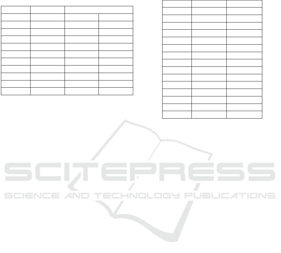
Table 1: Simulated production times for n products in
PlaSMA and Spin simulation, including the amount of
RAM required to compute the given result. (* indicates that
the whole state space was searched.)
PlaSMA Spin (Inflexible)
Products Sim. Time Sim. Time RAM
2 4:01 3:24 987 MB*
3 4:06 3:34 2154 MB*
4 4:46 3:56 557 MB
5 4:16 4:31 587 MB
6 5:29 4:31 611 MB
7 5:18 5:08 636 MB
8 5:57 5:43 670 MB
9 6:00 5:43 692 MB
10 6:08 5:43 715 MB
20 9:03 8:56 977 MB
Core(TM) i7-4710HQ CPU at 2.50 GHz, 16 GB of
RAM and Windows 10 (64 Bit). Second, a server
with an Intel(R) Xeon(R) CPU E5-4627 v2 at 3.30
GHz 128 GB of RAM and Windows Server 2012 R2
(64 Bit).
6.1 Inflexible Product Variants
For the first series of experiments, we predefined pro-
duction goals for each product: Products with even
IDs acquire clear bulbs, products with odd IDs ac-
quire colored ones.
Table 1 shows that in most cases the Spin model
checker proposes an optimal solution that is up to one
minute faster than the original MAS. While a certain
deviation between both simulations is unavoidable,
since the non-deterministic communication processes
between shuttles, products and stations are not con-
sidered in the Promela model, results clearly indicate
that the agents’ decision making leaves a lot of room
for improvement, especially, under consideration of
the agents’ flexibility: The autonomous products in
the original MAS are able to decide, which product
variant they want to become to counter waiting times
at stations.
However, the Spin model checker also reveals
considerable limitations. While the state space of ex-
periments with n ∈ {2, 3} products can be searched
completely even on a standard notebook, experiments
with n > 3 shuttles easily exhaust 128 GB of RAM
on our server without ever completing the search of
the whole state space. Luckily, potentially good re-
sults can be found early on: Table 1 shows that even
in experiments that exhausted 128 GB of RAM, the
best results were found before the search space filled
2 GB of RAM. However, a valid solution for n > 30
shuttles could not be computed by the model checker
Table 2: Sequences of events for n = 2 products.
(Product ⇒ Station, where ⇒ indicates a finished produc-
tion step.)
PlaSMA Spin (Infl.) Spin (flex.)
0 ⇒ 4 0 ⇒ 4 0 ⇒ 4
1 ⇒ 2 1 ⇒ 4 1 ⇒ 4
0 ⇒ 3 2 ⇒ 4 2 ⇒ 4
2 ⇒ 1 0 ⇒ 3 0 ⇒ 3
0 ⇒ 2 2 ⇒ 3 1 ⇒ 3
1 ⇒ 4 1 ⇒ 2 0 ⇒ 2
0 ⇒ 0 1 ⇒ 1 2 ⇒ 2
2 ⇒ 4 2 ⇒ 2 1 ⇒ 2
0 ⇒ 5 1 ⇒ 0 0 ⇒ 0
1 ⇒ 1 0 ⇒ 2 2 ⇒ 1
2 ⇒ 2 2 ⇒ 0 1 ⇒ 0
1 ⇒ 0 0 ⇒ 0 2 ⇒ 0
2 ⇒ 0 1 ⇒ 5 1 ⇒ 5
1 ⇒ 5 2 ⇒ 5 0 ⇒ 5
2 ⇒ 5 0 ⇒ 5 2 ⇒ 5
before the RAM on our server was exhausted.
Regarding computation time, experiments in both
Spin and the PlaSMA system provided results within
few minutes. It is mentionable though, that Spin pro-
vides the above results in shorter computation time
than the corresponding PlaSMA simulation. How-
ever, exhausting the servers RAM takes about 20 min-
utes and slightly exceeds PlaSMAs computation time.
6.2 Flexible Product Variants
In a second series of experiments, we allowed the
model checker to decide, which products to provide
with a colored or clear bulb. In these experiments, a
desirable final state is reached when all products have
returned to the storage station (station 5) and the dif-
ference d between the amount of both product vari-
ants is 0 ≤ d ≤ 1.
In these experiments, the model checker has even
more possibilities to branch its search space. There-
fore, it is hardly surprising that problems with n > 3
shuttles could not be computed on either of our test
machines. For n = 2 shuttles, the model checker pro-
poses a solution that takes 3:21 seconds and therefore
is 3 seconds faster than the inflexible solution. For
n = 3 shuttles, the difference is 10 seconds, as the
production takes 3:24 seconds of simulation time.
A closer look at the sequence of events reveals,
that a flexible choice of product variants allows prod-
ucts to overtake stations more efficiently, as illustrated
in Table 2.
Branch-and-Bound Optimization of a Multiagent System for Flow Production using Model Checking
35

7 CONCLUSIONS
In this paper, we presented a novel approach for
model checking an industrial production line. The re-
search was motivated by our interest in finding and
comparing centralized and distributed solutions to the
optimization problems in autonomous production sys-
tems.
The formal model reflects the routing and schedul-
ing of shuttles in the multiagent system. Nodes of the
rail network were modeled as processes, the edges
between the nodes were modeled as communication
channels. Additional constraints to the order of pro-
duction steps enable to carry out a complex planning
task.
Our results clearly indicate a lot of room for im-
provement in the decentralized solution, since the
model checker found more efficient ways to route and
schedule the shuttles on several occasions. Further-
more, the model checker could derive optimized plans
of several thousand steps.
In future work, we will consider a larger param-
eter space for the model checker. We are also think-
ing of applying an action planner or a general game
player for comparison. We do not expect a drastic im-
provement in state space size, as the model languages
(PDDL (Hoffmann and Edelkamp, 2005) and GDL
(Love et al., 2006)) are considerably different and do
not have native support for communication queues.
However as in directed model checking (Edelkamp
et al., 2001), the integration of informative heuristics
might help to guide the search process towards find-
ing the goal.
ACKNOWLEDGEMENTS
This research was partly funded by the International
Graduate School for Dynamics in Logistics (IGS) of
the University of Bremen.
REFERENCES
Armando, A., Mantovani, J., and Platania, L. (2006).
Bounded model checking of software using SMT
solvers instead of SAT solvers. In SPIN, pages 146–
162. Springer.
Bhat, U. (1986). Finite capacity assembly-like queues.
Queueing Systems, 1:85–101.
Biere, A., Cimatti, A., Clarke, E., and Zhu, Y. (1999). Sym-
bolic model checking without BDDs. In Tools and
Algorithms for the Construction and Analysis of Sys-
tems.
Bo
ˇ
sna
ˇ
cki, D. and Dams, D. (1998). Integrating Real
Time Into Spin: A Prototype Implementation. In
Budkowski, S., Cavalli, A., and Najm, E., editors,
FORTE/PSTV, volume 6 of IFIP The International
Federation for Information Processing, pages 423–
438. Springer.
Bracht, U., Geckler, D., and Wenzel, S. (2011). Digi-
tale Fabrik: Methoden und Praxisbeispiele. Springer,
Berlin/Heidelberg.
Brinksma, E. and Mader, A. (2000). Verification and opti-
mization of a PLC control schedule. In SPIN, volume
1885, pages 73–92.
B
¨
urckert, H.-J., Fischer, K., and Vierke, G. (2000). Holonic
transport scheduling with teletruck. Applied Artificial
Intelligence, 14(7):697–725.
Burman, M. (1995). New results in flow line analysis. PhD
thesis, Massachusetts Institute of Technology.
Cimatti, A., Giunchiglia, E., Giunchiglia, F., and Traverso,
P. (1997). Planning via model checking: A decision
procedure for AR. In ECP, pages 130–142. Springer.
Cimatti, A., Roveri, M., and Traverso, P. (1998). Auto-
matic OBDD-based generation of universal plans in
non-deterministic domains. In AAAI, pages 875–881.
Clarke, E., Grumberg, O., and Peled, D. (2000). Model
Checking. MIT Press.
Dorer, K. and Calisti, M. (2005). An adaptive solution to
dynamic transport optimization. In AAMAS, pages
45–51. ACM.
Edelkamp, S., Lluch-Lafuente, A., and Leue, S. (2001). Di-
rected model-checking in HSF-SPIN. In SPIN, pages
57–79.
Edelkamp, S. and Reffel, F. (1998). OBDDs in heuristic
search. In KI, pages 81–92.
Edelkamp, S. and Sulewski, D. (2008). Flash-efficient LTL
model checking with minimal counterexamples. In
SEFM, pages 73–82.
Fischer, K., M
¨
uller, J. R. P., and Pischel, M. (1996). Coop-
erative transportation scheduling: an application do-
main for dai. Applied Artificial Intelligence, 10(1):1–
34.
Fox, M. and Long, D. (1999). The detection and exploration
of symmetry in planning problems. In IJCAI, pages
956–961.
Fujimoto, R. (2000). Parallel and Distributed Simulation
Systems. Wiley & Sons.
Ganji, F., Morales Kluge, E., and Scholz-Reiter, B. (2010).
Bringing Agents into Application: Intelligent Prod-
ucts in Autonomous Logistics. In Schill, K., Scholz-
Reiter, B., and Frommberger, L., editors, Artificial in-
telligence and Logistics (AiLog) - Workshop at ECAI
2010, pages 37–42.
Gerth, R., Peled, D., Vardi, M., and Wolper, P. (1995). Sim-
ple on-the-fly automatic verification of linear temporal
logic. In PSTV, pages 3–18. Chapman & Hall.
Giunchiglia, F. and Traverso, P. (1999). Planning as model
checking. In ECP, pages 1–19.
Godefroid, P. (1991). Using partial orders to improve auto-
matic verification methods. In CAV, pages 176–185.
Greulich, C., Edelkamp, S., and Eicke, N. (2015). Cyber-
Physical Multiagent-Simulation in Production Logis-
tics. In MATES, pages 119–136. Springer.
ICAART 2016 - 8th International Conference on Agents and Artificial Intelligence
36

Harrison, J. (1973). Assembly-like queues. Journal of Ap-
plied Probability, 10:354–367.
Helias, A., Guerrin, F., and Steyer, J.-P. (2008). Using
timed automata and model-checking to simulate ma-
terial flow in agricultural production systems – appli-
cation to animal waste management. Computers and
Electronics in Agriculture, 63(2):183–192.
Himoff, J., Rzevski, G., and Skobelev, P. (2006). Magenta
technology multi-agent logistics i-scheduler for road
transportation. In AAMAS, pages 1514–1521. ACM.
Hoffmann, J. and Edelkamp, S. (2005). The deterministic
part of IPC-4: An overview. Journal of Artificial In-
telligence Research, 24:519–579.
Hoffmann, J., Kissmann, P., and Torralba,
´
A. (2014). ”dis-
tance”? Who cares? Tailoring merge-and-shrink
heuristics to detect unsolvability. In ECAI, pages 441–
446.
Holzmann, G. J. (2004). The SPIN Model Checker - primer
and reference manual. Addison-Wesley.
Hopp, W. and Simon, J. (1989). Bounds and heuristics for
assembly-like queues. Queueing Systems, 4:137–156.
Jensen, R. M., Veloso, M. M., and Bowling, M. H. (2001).
Obdd-based optimistic and strong cyclic adversarial
planning. In ECP.
Kautz, H. and Selman, B. (1996). Pushing the envelope:
Planning propositional logic, and stochastic search. In
ECAI, pages 1194–1201.
Kupferschmid, S., Hoffmann, J., Dierks, H., and Behrmann,
G. (2006). Adapting an AI planning heuristic for di-
rected model checking. In SPIN, pages 35–52.
Lipper, E. and Sengupta, E. (1986). Assembly-like queues
with finite capacity: bounds, asymptotics and approx-
imations. Queueing Systems, pages 67–83.
Lluch-Lafuente, A. (2003). Symmetry reduction and
heuristic search for error detection in model checking.
In MOCHART, pages 77–86.
Love, N. C., Hinrichs, T. L., and Genesereth, M. R. (2006).
General Game Playing: Game Description Language
Specification. Technical Report LG-2006-01, Stan-
ford Logic Group.
Manitz, M. (2008). Queueing-model based analysis of as-
sembly lines with finite buffers and general service
times. Computers & Operations Research, 35(8):2520
– 2536.
Morales Kluge, E., Ganji, F., and Scholz-Reiter, B. (2010).
Intelligent products - towards autonomous logistic
processes - a work in progress paper. In PLM, pages
348 – 357, Bremen.
Nau, D., Ghallab, M., and Traverso, P. (2004). Automated
Planning: Theory & Practice. Morgan Kaufmann
Publishers Inc., San Francisco, CA, USA.
Nissim, R. and Brafman, R. I. (2013). Cost-optimal plan-
ning by self-interested agents. In AAAI.
Parragh, S. N., Doerner, K. F., and Hartl, R. F. (2008).
A Survey on Pickup and Delivery Problems Part II:
Transportation between Pickup and Delivery Loca-
tions. Journal f
¨
ur Betriebswirtschaft, 58(2):81–117.
Rekersbrink, H., Ludwig, B., and Scholz-Reiter, B. (2007).
Entscheidungen selbststeuernder logistischer Objekte.
Industrie Management, 23(4):25–30.
Russell, S. J. and Norvig, P. (2010). Artificial Intelligence -
A Modern Approach. Pearson Education, 3rd edition.
Ruys, T. C. (2003). Optimal scheduling using branch and
bound with SPIN 4.0. In SPIN, pages 1–17.
Ruys, T. C. and Brinksma, E. (1998). Experience with lit-
erate programming in the modelling and validation of
systems. In TACAS, pages 393–408.
Saffidine, A. (2014). Solving Games and All That. PhD
thesis, University Paris-Dauphine.
Valmari, A. (1991). A stubborn attack on state explosion.
Lecture Notes in Computer Science, 531:156–165.
Wooldridge, M. (2000). Reasoning about Rational Agents.
The MIT Press.
Wooldridge, M. (2002). An Introduction to Multi-Agent
Systems. Wiley and Sons, Chichester, UK.
Branch-and-Bound Optimization of a Multiagent System for Flow Production using Model Checking
37
