SCDML: A Language for Conceptual Data Modeling in Model-based
Systems Engineering
Christian Hennig
1
, Tobias Hoppe
2
, Harald Eisenmann
1
, Alexander Viehl
2
and Oliver Bringmann
3
1
Space Systems, Airbus Defence and Space, Friedrichshafen, Germany
2
Intelligent Systems and Production Engineering, FZI Research Center for Information Technology, Karlsruhe, Germany
3
Wilhelm-Schickard-Institute for Computer Science, Eberhard-Karls, University of Tübingen, Tübingen, Germany
Keywords: Systems Engineering, Model-based Systems Engineering, Conceptual Data Modeling, Data Modeling Lan-
guage, OWL, Fact based Modeling.
Abstract: This paper presents the design and usage of a language for Conceptual Data Modeling in Model-based
Systems Engineering. Based on an existing analysis of presently employed data modeling languages, a new
conceptual data modeling language is defined that brings together characteristic features from software en-
gineering languages, features from languages classically employed for knowledge engineering, as well as
entirely newly developed functional aspects. This language has been applied to model a spacecraft as an ex-
ample, demonstrating its utility for developing complex, multidisciplinary systems in the scope of Model-
based Space Systems Engineering.
INTRODUCTION
The industrial setting for producing systems to be
deployed in space, such as satellites, launch systems,
or science spacecraft, involves a multitude of engi-
neering disciplines. Each involved discipline has
their own view on the system to be built, along with
their own models, based on their own model seman-
tics. For forming a consistent picture of the system,
information from all relevant discipline-specific
models is integrated towards a holistic, interdiscipli-
nary system model, forming the practice of Model-
Based Systems Engineering (MBSE).
A variety of approaches exist for building such
models. On the one hand there are approaches
strongly driven by the implementation technologies
that are used for producing engineering applications,
relying on data models specified in UML or Ecore.
On the other hand there are techniques almost ex-
clusively focused on representing knowledge that
can also be used to specify data, such as the Web
Ontology Language OWL or Object Role Modeling
ORM. Each of these approaches has its own charac-
teristics with both shortcomings and unique benefits.
Following from an analysis of available lan-
guages conducted in an earlier paper (Hennig, et al.,
2015), this paper addresses the lack of an adequate
conceptual data modeling language in MBSE by
making the following contributions:
Design of a language called SCDML that in-
tegrates software-production aspects and
knowledge-oriented modelling aspects
Design of a conceptual data model in SCDML
Demonstration of SCDML’s utility by provid-
ing a system model with the example of the
GravitySat satellite.
BACKGROUND
The Systems Engineering Practice
In many industrial engineering projects today, a
multitude of disciplines is involved in building a
system. For space projects such as satellites, launch
vehicles, and resupply spacecraft these disciplines
involve, only to name a few, mechanical engineer-
ing, electrical engineering, thermal engineering,
requirements engineering, software engineering,
verification engineering, and their respective sub-
disciplines. Each of these disciplines specifies their
designs and verifies specific aspects of the system.
In order to provide an all-encompassing understand-
ing of the system, the unique, yet complementary,
views from every involved discipline are combined.
The science and art of integrating different views on
184
Hennig, C., Hoppe, T., Eisenmann, H., Viehl, A. and Bringmann, O.
SCDML: A Language for Conceptual Data Modeling in Model-based Systems Engineering.
DOI: 10.5220/0005676501840192
In Proceedings of the 4th International Conference on Model-Driven Engineering and Software Development (MODELSWARD 2016), pages 184-192
ISBN: 978-989-758-168-7
Copyright
c
2016 by SCITEPRESS – Science and Technology Publications, Lda. All rights reserved
one system towards system thinking is called Sys-
tems Engineering. As NASA (2007) elegantly puts
it: “Systems engineering is a holistic, integrative
discipline, wherein the contributions of structural
engineers, electrical engineers, mechanism design-
ers, power engineers, human factors engineers, and
many more disciplines are evaluated and balanced,
one against an-other, to produce a coherent whole
that is not dominated by the perspective of a single
discipline.”
Systems Engineering and Models
Many of the engineering activities performed inside
these domains are already well supported by com-
puter-based models. Mechanical design models built
with tools such as CATIA V5, mechanical analysis
models built with tools such as PATRAN, and ther-
mal analysis models built with tools such as
ESATAN-TMS are well established in the space
engineering community today. Furthermore, re-
quirements models based on DOORS, software
design models specified in the Ecore language using
the Eclipse Modeling Framework, as well as mission
design models specified in SysML (OMG, 2015)
play important roles. Furthermore, “traditional” tools
such as Excel or Visio are used on a regular basis for
specifying models. These tools and the models they
produce differ significantly from each other (Kogal-
ovsky & Kalinichenko, 2009). They are provided by
different vendors, rely on different implementation
technologies and are based on different formats.
Each model and the associated design methodology
follow their own principles and paradigms and de-
fine their very own semantics. As a result of this
heterogeneity, these models and tools are not well
integrated and interconnected with each other and
with the multi-domain systems engineering process
(INCOSE, 2014). For a truly multidisciplinary rep-
resentation of a system, relevant aspects from all
involved domains and their models need to be com-
bined on the model level (Eisenmann, 2012).
Describing System-Wide Models
A computer-based model consists of two basic parts.
The layer directly visible to the user is the instance
model or user model, where the user enters his data
and works with it. In order to specify what bits of
information can be described in the user model, a
data model or meta-model is required that specifies
the concepts of the user model (Hong & Maryanski,
1990). It is worthy to note that meta-model is a rela-
tive term. It describes concepts one abstraction level
above the model that is currently the focus of inter-
est.
The System Model
For such models in engineering the “working level”
is represented by the so-called system model or user
model. In this model the system of interest is de-
scribed. This includes domain-specific aspects of the
system and the data relevant to systems engineering
activities. The system model may contain data such
as all the requirements that are specified for the
system and their means of verification, the system’s
product structure, its mechanical, electrical, or in-
formational interfaces, the functions it performs, the
system’s behavior, or its key design parameters
(ESA, 2011).
The Conceptual Data Model
In order to be able to specify the system model, the
concepts that define it have to be described some-
how. This is achieved by using the conceptual data
model (CDM), forming the meta-model of the user
model. The CDM describes the entities, conceptual
structures, and characteristic relationships of the
Universe of Discourse (UoD) (Kogalovsky & Kali-
nichenko, 2009), (Halpin & Morgan, 2008), forming
the backbone of MBSE (Eisenmann, 2012).
It is worthy to note that the currently predomi-
nant approach in most engineering domains is to
exchange knowledge between all discipline-specific
models in a document-based fashion. This means
that the knowledge stored in a computer model of a
specific domain is written in a document which is
then handed to another domain. Engineers from the
other domain then extract their required bits of in-
formation from the document and employ it accord-
ingly. It is evident that this document-based ex-
change of information is a tedious process prone to
errors and inconsistencies, resulting in a significant
amount of unnecessary overhead. Consequently, a
strong tendency to support such engineering pro-
cesses with models, making the information accessi-
ble in an automated way, can be observed. It is ex-
pected that model-based information exchange sig-
nificantly reduces the effort and consequently the
costs involved in inter-disciplinary and inter-domain
information exchange. Moreover, engineering pro-
cesses relying on MBSE are expected to benefit
from improved quality, increased productivity, and
reduced risk (Friedenthal, et al., 2009).
SCDML: A Language for Conceptual Data Modeling in Model-based Systems Engineering
185
The Data Modeling Language
Being the center of MBSE-based activities, the
CDM can be specified in a number of languages. For
developing relational databases, the conceptual
model is often specified in Entity–Relationship
models (Halpin & Morgan, 2008) or MS Access
database schemata. For promoting tool integration,
the EXPRESS language (ISO, 2004) was developed.
Other approaches directly rely on languages that are
usually employed for specifying software, such as
UML or Ecore (Kogalovsky & Kalinichenko, 2009),
(Olivé, 2007) while knowledge-focused modeling
languages such as Gellish (Van Renssen, 2005),
Object Role Modeling ORM (Halpin & Morgan,
2008) and the Web Ontology Language OWL
(W3C, 2012) have also been employed for specify-
ing a wide variety of UoDs. Some of those lan-
guages did not deliver the hoped for results (EX-
PRESS), others meanwhile reached their limits (ER,
Access, Gellish, UML) while yet others are rather
gaining momentum than losing ground (Ecore,
ORM, OWL) in the context of MBSE.
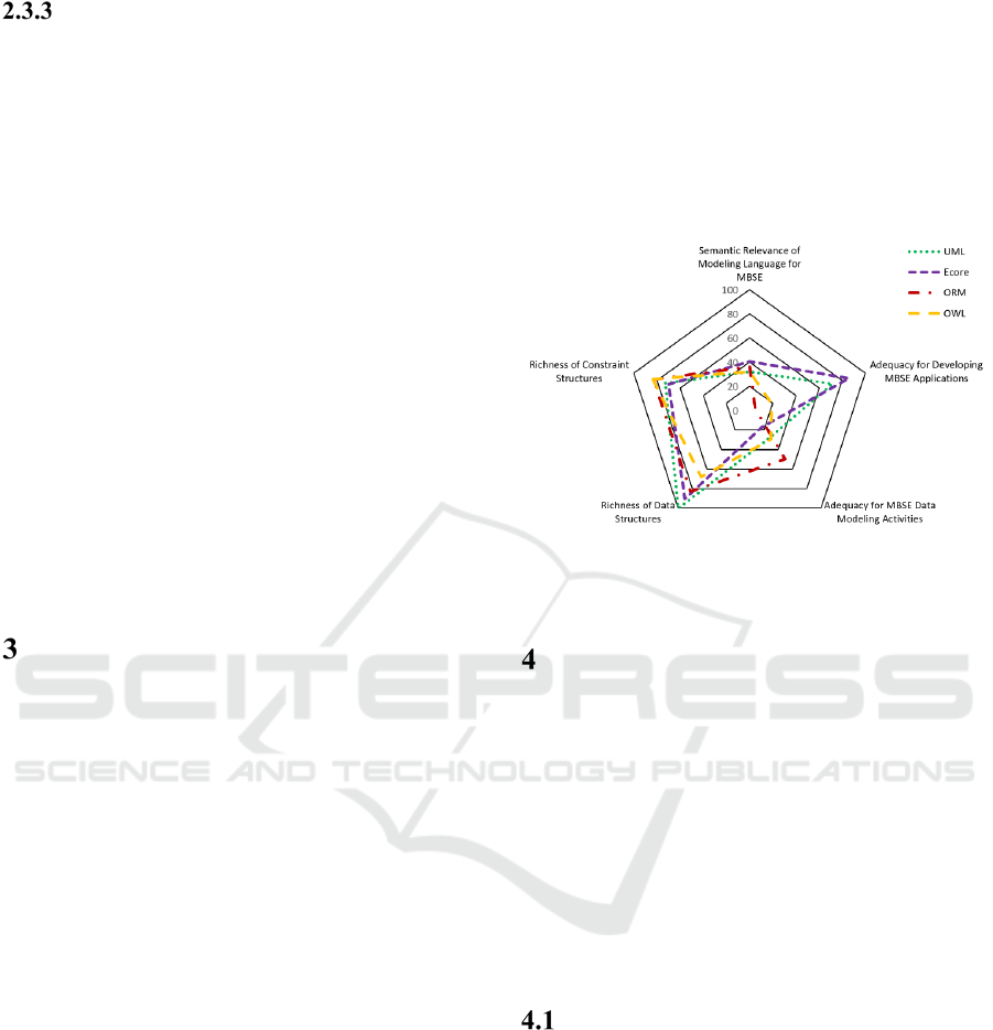
EVALUATION OF LANGUAGES
A thorough evaluation of the languages relevant for
conceptual data modeling in MBSE, UML, Ecore,
OWL and ORM, has been performed by Hennig, et
al. (2015). This analysis is based upon extensive
experience employing CDMs within projects (ESA,
2012) (ESA, 2013) (Fischer, et al., 2014) and exam-
ines the utility of these languages for MBSE by
evaluating a variety of characteristics in five differ-
ent categories. These include the semantic relevance
of the language for MBSE, its adequacy for develop-
ing software applications, the adequacy to support
data model engineering activities, the richness of
data structures and the richness of built-in constraint
structures. The results of the analysis are summa-
rized in Figure 1.
UML is well suited for software development,
but is not suited directly for conceptual data model-
ing in MBSE. It provides a sufficient amount of
different data structures and supports a variety of
semantic constraints. Ecore is similarly suited for
application development, but also falls short in the
semantic relevance and modeling activities catego-
ries. Its support for modeling data structures is ade-
quate, but the number of built-in constraints is not
sufficient. OWL is not directly suited for software
development and misses out on established data
structures, but provides a good number of built-in
constraints. ORM is also not directly suited for ap-
plication development, but is quite suited for the
activities performed in conceptual data modeling. It
provides a decent amount of data structures and
comes with a variety of useful built-in constraints.
The analysis also made evident that some features
that are desired in the context of applying MBSE in
the industry are not covered by any of these lan-
guages.
Figure 1: Comparison of selected data modeling languages
(Hennig et al., 2015).
LANGUAGE DESIGN
The analysis of modeling languages painted the
picture that there is currently no silver bullet for
conceptual data modeling. Each of the four exam-
ined languages has its characteristic merits, but the
ideal language does not exist. As a solution an ap-
proach that combines some of these languages is
proposed, incorporating and unifying the strong suits
of Ecore, ORM, and OWL. This integrated, domain-
specific conceptual data modeling language called
SCDML is elaborated further in the remainder of
this paper.
Language Design Alternatives
For developing a new language that encompasses the
advantageous functionality of the analyzed candi-
dates while doing away with their rather cumber-
some aspects a number of potential solutions can be
considered.
For instance, using existing ORM implementa-
tions in e.g. C++ as a central element is one ap-
proach. This structure could then be augmented by
OWL concepts and other needed enhancements.
However this approach does not cater to software
engineering activities such as generating application
code for implementations of the CDM. Another
MODELSWARD 2016 - 4th International Conference on Model-Driven Engineering and Software Development
186
possibility would be using OWL as basis, augment-
ing it with ORM concepts and using mappings to
UML for application development. However aug-
menting the OWL metamodel and transforming it
into UML would result in a considerable loss of
CDM semantics. Furthermore, the Open World
Assumption would pose a problem to CDM usage. A
third possibility would be to use UML as a data
modeling and software engineering structure, en-
hanced by stereotypes for facilitating some of
OWL’s functions. However, UML’s stereotyping
mechanism is somehow unsuited for this purpose.
The solution that was finally selected for this pa-
per will be outlined in the following paragraphs. It is
based on Ecore as a technological foundation, with
its suitability for code generation, enhanced with
ORM and OWL concepts, augmented with entirely
newly developed aspects.
SCDML Design
Technological Foundation
As technological foundation the Eclipse Modeling
Framework with its integrated specification lan-
guage Ecore has been selected. EMF already fulfils
several of the requested requirements, such as:
An effective software engineering process with
the ability to generate code for the basic applica-
tion structure from the specified Ecore model
The Closed World Assumption
A powerful language extension mechanism
through meta-modeling
Through instantiating the Ecore model a custom
language model can be described. This instantiation
defines the building blocks of the SCDML language.
This language consists of buildings blocks for de-
scribing model elements in ORM abstract syntax,
concepts for specifying life-cycle aspects of the data
model, concepts for defining engineering properties,
and some more. A detailed description of these lan-
guage building blocks will follow shortly.
Language Abstraction Levels
While the main concepts of SCDML are all defined
on the level that is instantiated by the Ecore model-
ing language, the whole modeling chain until a user
model can be specified involves modeling on a
number of abstraction levels.
The uppermost abstraction level is given by the
Ecore language. On this level the main Ecore
building blocks such as EClasses, EReferences,
EAttributes, are defined.
The next level is made up of instances of the
Ecore language concepts. The SCDML language
is specified on this level. This means that all en-
tities (called EntityTypes) that make up the
SCDML language are instances of EClass, the
references between them are instances of ERef-
erence, and so on. These concepts are then used
to instantiate the CDM.
On the CDM level the CDM is described by
instantiating the SCDML language. For instance
a model element with name Spacecraft would be
an instance of EntityType on the SCDML level.
The system model is described on user model
level, meaning that a thing with name GravitySat
would be an instance of the CDM concept Space-
craft.
Ecore
SCDML : Ecore
MyCDM : SCDML
MyUM : MyCDM
instanceOf
instanceOf
instanceOf
Traditional Ecore
Modeling Levels
SCDML
Modeling Levels
Modeling
Language
Conceptual Model
User Model
Not considered
Not instantiable
Modeling
Language
Conceptual
Modeling
Language
Conceptual Model
User Model
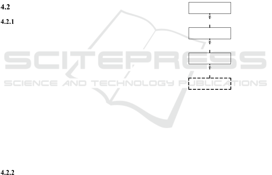
Figure 2: Modeling levels of SCDML.
However, while working from a conceptual point
of view, this four level architecture results in a pro-
found problem when being realized. The usual way
of modeling involves three levels, with the modeling
language on top, a conceptual model in the middle
level and a user model on the bottom level. The
language instantiates the conceptual model which in
turn instantiates the user model. This is also true in
the case of Ecore, where Ecore allows instantiation
of its concepts and code generation from the concep-
tual model, involving a total of three abstraction
levels. However, since the Ecore language is to be
extended with custom concepts, a fourth level, com-
prising of the conceptual modeling language, has to
be considered as well. This issue is illustrated in
Figure 2
.
SCDML: A Language for Conceptual Data Modeling in Model-based Systems Engineering
187
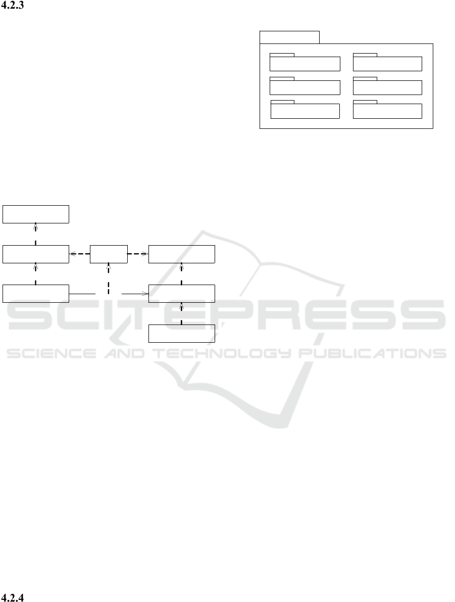
Model Transformation from
Conceptual Modeling Language to
Technical Modeling Language
For overcoming this limitation and gaining a fourth
abstraction level a model-to-model-transformation is
introduced. In the case of SCDML this transfor-
mation is based on OMG’s QVT standard (OMG,
January 2011). This transformation maps the con-
cepts defined in SCDML to native Ecore concepts.
Figure 3 shows the transformation from the con-
cepts directly defined in SCDML to plain Ecore
concepts. The left side can be seen as the conceptual
model, residing on the conceptual level defined in
the ANSI/X3/SPARC Report. The right side that is
not directly visible to the end-user can be seen as a
physical model residing on the internal level.
Ecore
SCDML : Ecore
MyCDM : SCDML
instanceOf
instanceOf
Ecore
MyCDM : Ecore
MyUM : MyCDM
Trans-
formation
instanceOf
instanceOf
transform
instanceOf
Figure 3: Model transformation from SCDML to Ecore.
There are specific mappings for different kinds
of concepts:
SCDML language concepts that have a more or
less direct analogy in Ecore are mapped directly.
Examples for these are EntityTypes/EClasses,
Packages/EPackages and Val-
ueFactTypes/EAttributes.
SCDML language concepts that do not have an
Ecore representation are mapped to OCL. This
applies to many constraints, such as subset con-
straints, object cardinality constraints, ring con-
straints, etc.
Some SCDML model elements are not mapped
per se, but rather copied to Ecore. This includes,
for instance, the means for side-loading concepts
that are to be present similarly on CDM and User
Model level, such as Categories and Engineer-
ingProperties.
SCDML Language Components
The SCDML language consists of several compo
nents, or packages, each implementing specific func-
tionality Figure 4.
SCDML
ORM Model Engineering
Rules
Model Maturity
Value Properties
Secondary Concepts
Figure 4: SCDML main packages.
The ORM package forms the core of CDMs. It
defines the abstract syntax of models and is based on
a pragmatic adoption of the ORM meta-model.
ORM concepts are complemented by custom con-
cepts that have been identified as being helpful for
conceptual modeling in MBSE, such as packages,
containment hierarchies, and a few custom con-
straints. The main model concepts are represented
by EntityTypes playing Roles. These Roles can be
played with other EntityTypes or with ValueTypes.
Roles and EntityTypes may have to adhere to a wide
variety of different Constraints that can be specified
in the CDM.
The Model Maturity package defines the func-
tionality for the conceptual modeler to define life-
cycle aspects of the CDM, as proposed by (Hennig
& Eisenmann, 2014). A number of model milestones
can be defined. Each constraint can be valid for all
or only at some milestones, enabling a controlled
model evolution.
The Rules package enables the modeling of pre-
defined kinds of business rules.
The Model Engineering package contains means
to model engineering processes and their related
artefacts and to connect these artefacts to elements
defined in the CDM, such as Packages, EntityTypes,
or Roles. This ensures a traceability of detailed en-
gineering processes to abstracted PDM processes, as
proposed by (Hennig & Eisenmann, 2014).
The Value Properties package implements
SysML’s QUDV model (OMG, 2015) with some
extensions for modelling physical properties, such as
a component’s mass in Kilogram, a power consump-
tion in Ampere or the thrust of an engine in Newton.
The Secondary Concepts package defines data
that can be specified on CDM level and side-loaded
on user model level while the CDM is already in-
stantiated (“at CDM runtime”). An important part of
these secondary concepts are formed by Engineer-
ingDataCategories which are used for side-loading
MODELSWARD 2016 - 4th International Conference on Model-Driven Engineering and Software Development
188
knowledge specific to an engineering discipline. The
logical compatibility of these concepts can be as-
sured with a reasoning algorithm similar to OWL
ontologies.
USING SCDML IN
SPACECRAFT SYSTEMS
ENGINEERING
For demonstrating the capabilities of SCDML a
sample CDM is modeled. The transformation and
the integrated code generating capabilities are em-
ployed for deriving an application that implements
the CDM and enables the definition of a user model.
The employed CDM is based on an evolution of the
ECSS-E-TM-10-23A conceptual data model (ESA,
2011). This evolution can be seen as a re-hosting of
the existing CDM defined in UML on SCDML
technologies, employing the now available con-
straints, rules, etc. and adjusting some of the speci-
fied data structures to suit current engineering needs.
The user model is based on a derivation from an
actual spacecraft project. A satellite called Grav-
itySat is modeled.
Engineering a CDM
In space system engineering an accurate representa-
tion of the product structure of the system is of high
importance. Satellite projects are often not built by
one company, but divided up into several parts that
are again divided up and distributed over several
levels of customer and supplier chains. The system’s
product structure serves as the central edifice at
which all kinds of information from different disci-
plines, different suppliers, and other sources comes
together. It is thus a central part of the CDM.
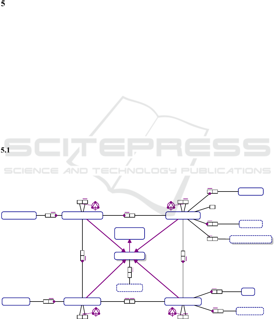
The ProductStructure consists of a number of
model elements, as illustrated by Figure 5
in ORM
syntax (Halpin & Morgan, 2008). The ProductTree
consists of several ElementDefinitions. An Ele-
mentDefinition is a rather abstract definition of a
part of the system that forms a loose hierarchy via
the contains role. An ElementDefinition must not
contain itself, must not form any cycles and must
always be intransitive. These properties are assured
through the acyclic constraint. An ElementDefinition
must be included in a ProductTree (Mandatory
Constraint) and can be included in at most one
ProductTree (Uniqueness Constraint). There can
only be one ProductTree for any system (Object
Cardinality Constraint). An ElementDefinition may
be abstract, may be identified by an ElementConfig-
Number and must have exactly one Multiplicity. The
ProductTree is a kind of SystemElement which must
have exactly one Name and may be abbreviated by
at most one Abbreviation.
The ProductStructure package consists of three
other SystemTrees, the ConfigurationTree, Assem-
blyTree and the Shelf. However, for early design
phases those model elements are not to be used and
are “locked” via the Forbidden Object Constraint.
Figure 5: ORM diagram of the Product Structure package of the CDM.
ElementDefinition
Abbreviation
Multiplicity
ElementConfigNumber
SystemElement
ElementConfiguration
ElementOccurrence ElementRealization
SerialNumber
NamedElement
(Name)
ProductTree
ConfigurationTree
AssemblyTree
Shelf
is abbreviated by
is abstract
has
isIdentifiedBy
isIdentifiedBy
isTypeFor / isTypedBy
isTypedBy / isTypeFor
configures
integrates / is integrated by
contains / isContainedBy
contains / isContainedBy contains / isContainedBy
contains / isContainedBy
consistsOf / isIncludedIn
isIncludedIn / consistsOf
isIncludedIn / consistsOf
consistsOf / isIncludedIn
#≤1
#≤1
#≤1
#≤1
SCDML: A Language for Conceptual Data Modeling in Model-based Systems Engineering
189
For instance, the ConfigurationTree is locked for
Phase 0 and Phase A until the Preliminary Require-
ments Review (PRR), but can be used in Phases B
and afterwards.
While the ProductTree specifies the Sys-
temElements as designed, for instance defining their
specified total mass, the ConfigurationTree defines
the configuration of the system. For instance the
spatial alignment of an ElementConfiguration in
terms of X/Y/Z coordinates within the spacecraft
reference frame is an important information that is
stored within the ConfigurationTree. The third tree
is made up by the AssemblyTree, defining a number
of different assemblies of one configuration. Into
this the AssemblyTree, a number ElementRealiza-
tions from the Shelf can be integrated. These ele-
ments represent the final as-built status and contain
as-built values, such as a serial number, an actual
weighed mass, or a measured power consumption.
What can also be modeled inside the CDM is a
library of reusable data structures such as Engineer-
ingDataCategories. These categories contain place-
holders for discipline-specific data that can be pre-
defined on CDM level (e.g. for reusability) and then
side-loaded into the user model during runtime.
Furthermore information about which categories are
not logically compatible with each other is included,
e.g. that a component cannot be hardware and soft-
ware at the same time, or a software component may
not have any physical characteristics such as mass.
Instantiating the CDM
Instantiating the CDM basically involves two steps.
The first step is to perform the model transformation
to plain Ecore, producing a model that can again be
instantiated. The second step is running the code
generation mechanism for producing application
code that allows instantiation of these defined con-
cepts, finally allowing the specification of a user
model.
Engineering a System
The satellite is modeled according to data relevant to
Phase B. This means that a ProductTree and a Con-
figurationTree are required, but an AssemblyTree is
specifically excluded via the previously defined
Forbidden Object Constraint in order to avoid over-
engineering the system in such an early phase. By
unlocking the concepts in the CDM step by step the
systems engineer is guided in having the right data at
the right time.
In order to refine the specification of system
components the principle of EngieeringDataCatego-
ries is used. These categories contain characteristic
knowledge about a component coming from differ-
ent disciplines. Due to these chunks of information
sometimes becoming very large and heterogeneous,
a reasoning mechanism is used to ensure a basic
amount of logical consistency.
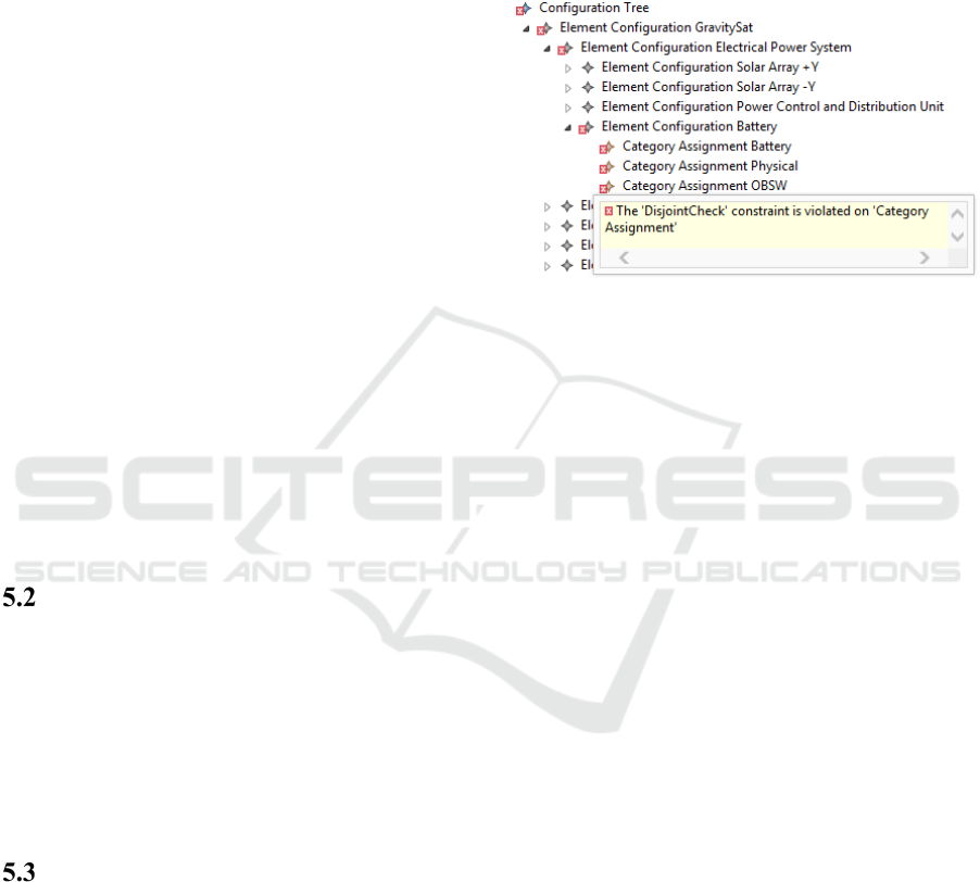
Figure 6: Automated ensuring of logical system model
consistency via disjoint checking.
As seen in
Figure 6
the Battery has three catego-
ries assigned. The first category contains characteris-
tics typical for batteries, such as nominal voltage,
number of cells, battery type, etc. These will proba-
bly be provided by the battery supplier. The second
category contains physical characteristics such as
mass and moments of inertia, e.g. provided through
an analysis by the mechanical engineering domain.
As a third category characteristics specific to pieces
of On-Board Software (OBSW) have been asserted
to the battery. However, since the Battery is neither
a piece of software, nor does it contain any software
in the traditional sense an error gets flagged in the
model. This is due to the fact that in the category
definition the knowledge has been asserted that
something that is as Battery (which is an electrical
power system component which is a hardware com-
ponent) cannot be a software component at the same
time (the categories have been made “disjoint” with
each other).
One critical design parameter for space systems
is the overall mass budget, consisting of the sum of
the mass of all elements. Often, the values for the
mass of a component start with an assumption e.g.
based on heritage, past experience, or extrapolation,
and become a backed value once sufficient infor-
mation is available. These values have margins in
order to account for the necessary amount of uncer-
tainty of the assumption or even the backed value.
These central design parameters are modeled using
EngineeringProperties. These properties form a
hierarchy for calculating budgets (sub and super
MODELSWARD 2016 - 4th International Conference on Model-Driven Engineering and Software Development
190
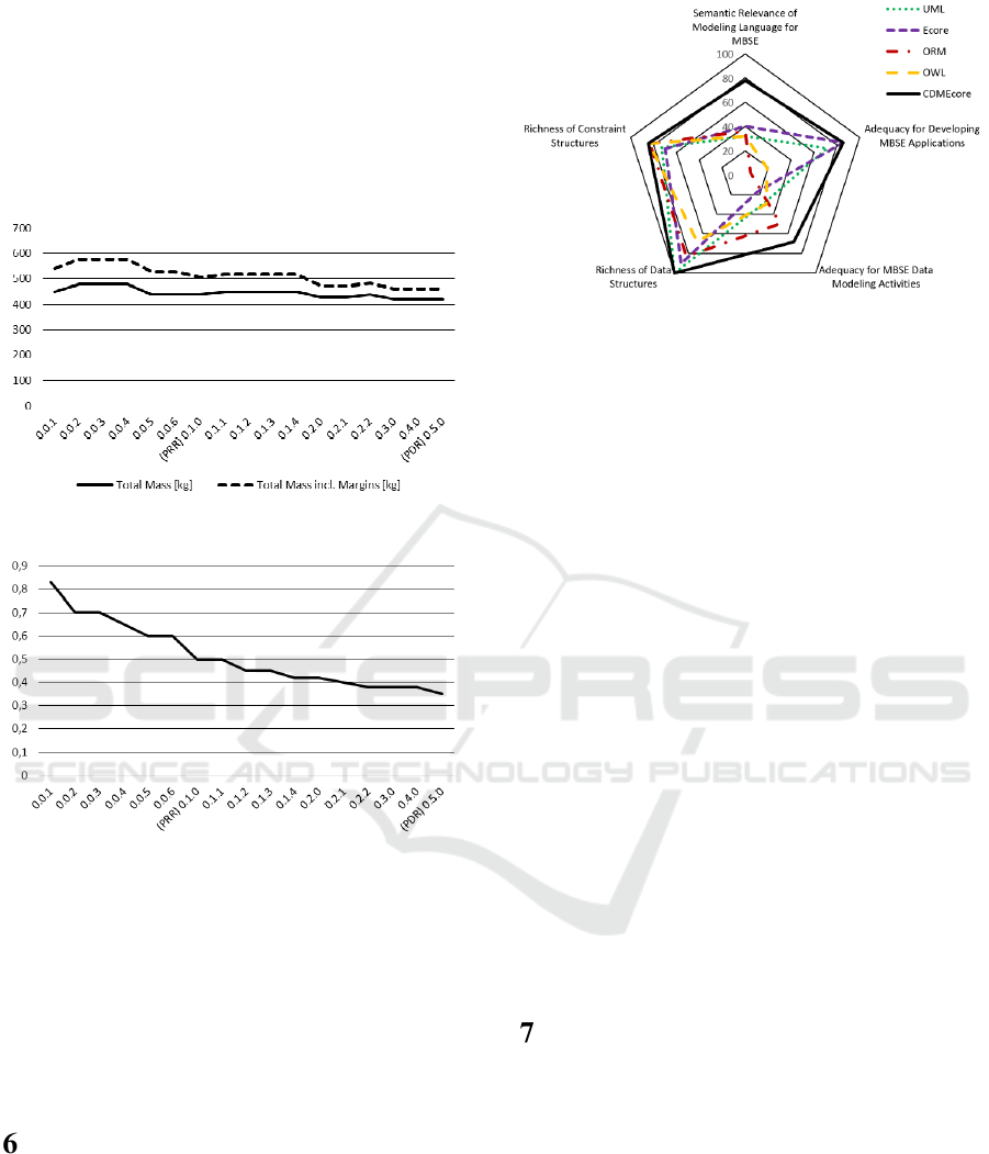
property values) that can be used for a variety of
system analyses.
Also considering the time dimension, the mass
properties of all system elements can be used to
calculate the total system mass. Once margins are
also accounted for a best case vs. worst case mass
property analysis can be provided, directly generated
from the current model and past versions (
Figure 7
).
Figure 7: Mass budget best case vs. worst case analysis.
Figure 8: Assumed parameters / total parameters.
Taking the amount of assumed parameters and
calculating their proportion to the amount of total
system parameters yields a value of 0 to 1. Ideally,
the final system design should evaluate to a value of
0 in the end. This factor can be used to measure
overall system design maturity and system design
quality (
Figure 8
).
FUNCTIONAL EVALUATION
OF SCDML
A category for SCDML can be added to the evalua-
tion presented previously in order to determine how
well it performs against the analyzed existing data
modeling languages (Figure 9).
In the category of semantic relevance for MBSE
SCDML performs significantly better than the other
Figure 9: Comparison of SCDML with selected modeling
languages.
languages due to being specifically developed for
this purpose. SCDML is based on the Closed World
Assumption, provides an abstract syntax under-
standable to non-modeling experts, supports model
life cycle aspects, and provides a language extension
interface. Some concepts such as business rules and
key engineering activities are supported, but not yet
elaborated as much as intended, which is why there
is still room for improvement. SCDML performs
similarly to Ecore for application development due
to the usage of Ecore as a technological basis. A key
design goal was to not offer less functionality for
developing applications compared to plain Ecore.
The category of adequacy for MBSE data modeling
activities is also supported better by SCDML than
by the other analyzed languages due to the possibil-
ity for linking the CDM to the model of an engineer-
ing process and its artefacts. Regarding richness of
data structures SCDML is able to support all of the
intended functionality, including n-ary relations,
objectification, packages and containment hierar-
chies. SCDML implements the constraints of ORM
and scores similarly in the constraint category.
CONCLUSIONS
Based on an analysis of existing solutions for con-
ceptual data modeling and an identification of their
shortcomings, a new language has been proposed,
encompassing the following key aspects:
Semantically strong modeling of CDMs in a
user-oriented language, allowing for a strong de-
scription of system concepts
Linking of CDM to engineering processes and
their artefacts
Fully automated code generation for basic sys-
tem model editors
Life-cycle-based management of the system
SCDML: A Language for Conceptual Data Modeling in Model-based Systems Engineering
191

model, guiding its maturity through all phases
Support for side-loading of reusable engineering
data and basic assurance of logical consistency
Support of key engineering activities on the
system model, such as assumption management,
parameter tracking and best case vs. worst case
analyses.
The development of engineering applications un-
til now either involved efficiently developing an
application with loosely defined semantics, or speci-
fying domain knowledge with strong semantics and
putting a large effort into implementation. The ap-
proach of SCDML bridges the gap between model-
ing languages focused on implementation, such as
UML and Ecore, and modeling languages highly
oriented on knowledge management, such as OWL
and ORM, with an introduction of functionality
tailored to MBSE usage. This significantly reduces
the time for prototyping an application for model-
based engineering with strong semantics, as well as
time for implementing the final application. Fur-
thermore functions that were not covered at all be-
fore, such as the time-dimension of CDMs, is now
able to significantly enhance the semantics of de-
signed models. This results in improved correctness
and completeness of the system to be designed at its
respective design stage.
REFERENCES
Eisenmann, H., 2012. VSD Final Presentation. [Online]
Available at: http://www.vsd-project.org/download/
presentations/VSD_P2_FP_2012-05-15_v3.pdf/
ESA, 2011. Space engineering - Space system data reposi-
tory. ESA Technical Memorandum ECSS-E-TM-10-
23A. s.l.:s.n.
ESA, 2012. The Virtual Spacecraft Design Project.
[Online] Available at: http://vsd.esa.int/
ESA, 2013. EGS-CC - European Ground Systems - Com-
mon Core. [Online] Available at: http://www. eg-
scc.esa.int/
Fischer, P. M., Eisenmann, H. & Fuchs, J., 2014. Func-
tional Verification by Simulation based on Preliminary
System Design Data. 6th International Workshop on
Systems and Concurrent Engineering for Space Appli-
cations (SECESA), 8-10 October.
Friedenthal, S., Griego, R. & Sampson, M., 2009. IN-
COSE Model-Based Systems Engineering Workshop.
[Online] Available at: http://www.incose.org/
Chicagoland/docs/SanDiego/3-18-
09%20INCOSE%20Model%20Based%20Systems
%20Engineering%20(MBSE)%20Workshop.pdf.
Halpin, T. & Morgan, T., 2008. Information Modeling and
Relational Databases. 2nd Hrsg. Burlington: Morgan
Kaufmann.
Hennig, C. & Eisenmann, H., 2014. Applying Selected
Knowledge Management Technologies and Principles
for Enabling Model-based Management of Engineer-
ing Data in MBSE. 6th International Workshop on
Systems and Concurrent Engineering for Space Appli-
cations (SECESA), 8-10 October.
Hennig, C., Eisenmann, H., Viehl, A. & Bringmann, O.,
2015. On Languages for Conceptual Data Modeling in
Multi-Disciplinary Space Systems Engineering. An-
gers, France, s.n.
Hong, S. & Maryanski, F. J., 1990. Using a Meta Model to
Represent Object-Oriented Data Models. 6th Interna-
tional Conference on Data Engineering, 5-9 Febuary,
pp. 11-19.
INCOSE, 2014. Systems Engineering Vision 2025.
[Online] Available at: http://www.incose.org/ Product-
sPubs/products/sevision2025.aspx.
ISO, 2004. ISO 10303-11: Industrial automation systems
and integration – product data representation and ex-
change – Part 11: Description methods: The EX-
PRESS language reference manual.. s.l.:s.n.
Kogalovsky, M. R. & Kalinichenko, L. A., 2009. Concep-
tual and Ontological Modeling in Information Sys-
tems. Programming and Computer Software, 35(5),
pp. 241-256.
NASA, 2007. NASA Systems Engineering Handbook
(NASA-SP-2007-6105) Rev1, s.l.: s.n.
Olivé, A., 2007. Conceptual Modeling of Information
Systems. Berlin: Springer.
OMG, 2015. OMG Systems Modeling Language (OMG
SysML). s.l.:s.n.
OMG, January 2011. Meta Object Facility (MOF) 2.0
Query/View/ Trans-formation, v1.1. s.l.:s.n.
Van Renssen, A. S. H. P., 2005. Gellish - A Generic Ex-
tensible Ontological Language, Delft: Technische
Universiteit Delft.
W3C, 2012. OWL 2 Web Ontology Language Primer
(Second Edition). [Online] Available at: http://www.
w3.org/TR/owl2-primer/
MODELSWARD 2016 - 4th International Conference on Model-Driven Engineering and Software Development
192
