
Geometric Eye Gaze Tracking
Adam Strupczewski
1
, Bła
˙
zej Czupry
´
nski
1
, Jacek Naruniec
2
and Kamil Mucha
1
1
Samsung Electronics Poland, Warsaw, Poland
2
Warsaw University of Technology, Warsaw, Poland
Keywords:
Eye Gaze Tracking, Head Pose Tracking, Iris Localization, Feature Matching, Pose Estimation.
Abstract:
This paper presents a novel eye gaze estimation method based on calculating the gaze vector in a geometric
approach. There have been many publications in the topic of eye gaze estimation, but most are related to
using dedicated infra red equipment and corneal glints. The presented approach, on the other hand, assumes
that only an RGB input image of the user’s face is available. Furthermore, it requires no calibration but only
simple one-frame initialization. In comparison to other systems presented in literature, our method has better
accuracy. The presented method relies on determining the 3D location of the face and eyes in the initialization
frame, tracking these locations in each consecutive frame and using this knowledge to estimating the gaze
vector and point where the user is looking. The algorithm runs in real time on mobile devices.
1 INTRODUCTION AND
RELATED WORK
Eye gaze tracking is an important aspect of computer
vision as it can be applied to many purposes: enhanc-
ing human-computer interfaces (HCI), support for the
disabled or user profiling are just a few. The exact
spot observed by the user is the combined result of
how their head is placed and how their eyes are ori-
ented. As is mentioned in one of the most recent sur-
veys on the topic (Hansen and Ji, 2010), the number
of publications and possible approaches to tackle the
problem is very large. We wanted to provide a system
that would be accurate and useful to the largest possi-
ble audience - so requiring only a simple webcam to
perform the gaze estimation task.
No head mounted devices meet this criterion for
obvious reasons. Also, purely statistical approaches
based on Markov Chains or neural networks have
been rejected because of the tiresome calibration that
is required and relatively low accuracy. In gen-
eral, appearance-based methods report lower accu-
racy than model-based methods. One of the most
accurate appearance-based methods (Lu et al., 2014)
does report an impressive accuracy, but requires tire-
some calibration for each user, and also doesn’t work
in real-time.
Surprisingly, the current state-of-the-art approach
rather deals with the eyes only, neglecting the head
motion. The two leading companies that produce
commercial eye trackers, Tobii and SensoMetric In-
struments, use remote trackers with a system of in-
frared illuminators that produce corneal reflections on
the eyeball surface and thus allow inferring the 3D
cornea orientation relative to the camera. These al-
gorithms are described for example in (Ohno et al.,
2002; Hennessey et al., 2006). Besides requiring so-
phisticated infra red cameras, they require personal
calibration to overcome the individual discrepancy
between the optical axis and line of sight.
There have been many studies on using a simple
webcam for eye gaze tracking. One approach is to in-
fer the gaze direction from the elliptical shape of the
observed limbus. A recent study of this performed
on a tablet has been published (Wood and Bulling,
2014). Unfortunately, the reported accuracy is quite
low and requires a very high resolution image of the
eye, something difficult to obtain in an uncontrolled
environment. Other proposed methods are mostly
based on relative iris and eye corner location analysis.
Ishikawa et al. (Ishikawa et al., 2004) use a geomet-
ric eye model where the gaze direction is inferred as
the head pose direction and modified by the eye ori-
entation. The eye orientation relative to the initial one
is found by detecting the iris center and eye corners.
While impressive results have been reported (3.2 de-
gree accuracy under significant head movements), we
have implemented a similar approach and found nu-
merous problems. Most importantly, the AAM is in
general incapable of providing accurate head pose es-
446
Strupczewski, A., Czupry
´
nski, B., Naruniec, J. and Mucha, K.
Geometric Eye Gaze Tracking.
DOI: 10.5220/0005676304440455
In Proceedings of the 11th Joint Conference on Computer Vision, Imaging and Computer Graphics Theory and Applications (VISIGRAPP 2016) - Volume 3: VISAPP, pages 446-457
ISBN: 978-989-758-175-5
Copyright
c
2016 by SCITEPRESS – Science and Technology Publications, Lda. All rights reserved
timates for different people. Additionally, the eye cor-
ners cannot be reliably detected with high accuracy
in uncontrolled conditions. Moreover, when uncon-
trolled simultaneous head and eye movements are per-
formed, the system produces high errors. In (Kim and
Kim, 2007) a similar system is described, but the re-
ported eye gaze tracking accuracy is only around 10
degrees.
Others (Valenti et al., 2009) propose to perform
eye gaze tracking by analyzing the relative position
of the pupil and the eye corners. The method is based
on 9-point calibration and on interpolation of the lo-
cations from calibration during tracking. This method
does not account for considerable head movements
and completely ignores head rotations. Furthermore,
the method strongly relies on the initial calibration
and if this is inaccurate, it needs to be performed
again. A significant improvement on this concept was
presented in (Valenti et al., 2012). This method as-
sumes that the head pose determines a specific field
of view, whereas the eye orientations can influence
which part of this field of view is observed. This way,
an initial 9-point calibration with a frontal face pose
can be used for any other pose as well. A cylindrical
head model and optical flow are used for head pose
estimation following the algorithm in (Xiao et al.,
2002). Furthermore, a hybrid framework is presented
where the eye center detection can be used to refine
the head pose estimation by so called eye location
cues, while the eye locations can in turn be refined
by so called head pose cues.
The work presented in (Valenti et al., 2012) seems
to be the best purely webcam based eye gaze tracking
system so far, which works also under limited head
movements. It has a number of drawbacks, however.
Firstly, it depends on initial multiple point calibration,
which is an inconvenience. Secondly, the calibration
data is used for means of interpolation within the de-
duced field of view. This in itself limits the maximum
achievable accuracy, as the point of regard does not
stem from a true geometric model. Furthermore, the
isophote based iris localisation and head pose estima-
tion both leave space for improvement.
We propose a new direct geometrical method of
eye gaze direction estimation. Similarly as the ap-
proach of (Valenti et al., 2012), it relies on head pose
estimation and iris localization. The main concept of
our method is different, however. It is based on an
explicit 3D geometric model where the eye gaze is
defined as a vector passing through specific points of
the eye. These points are calculated to directly de-
termine the gaze vector, without any interpolation or
statistical inference. In the course of development
we have also designed a highly robust and accurate
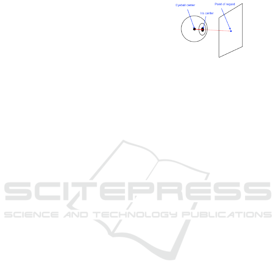
Figure 1: Eye gaze tracking method concept.
head pose estimation method, which we believe lies
in the state-of-the-art category. It is an expansion of
renown model-based head pose estimation methods
(Xiao et al., 2002; Jang and Kanade, 2004; Morency
et al., 2008; Liao et al., 2010). Finally, we have
improved previously published iris localization algo-
rithms (Zhang et al., 2007; Zhou et al., 2011) to use
head pose information for adaptive tuning.
The contributions of this paper are the following:
1. A complete geometric method for eye gaze track-
ing which can be used without user-specific cali-
bration; the method can use RGB only input
2. A novel hybrid method for accurate head pose es-
timation
3. A novel adaptive method for iris localisation
4. A framework to evaluate the accuracy of eye gaze
tracking
2 PROPOSED METHOD
We propose a straightforward geometric method that
calculates the gaze vector as a line in 3D space cross-
ing the eye center, the pupil center and the observed
screen. The intersection of this line with the screen
is the point of regard (POR) on the screen. The pupil
center is approximately the same point as the iris cen-
ter. Therefore, we always localize the iris and use its
center as the pupil center. The concept of the pro-
posed method is shown in Figure 1.
The big benefit of this approach compared to other
approaches is that its accuracy is not inherently lim-
ited by the method. If accurate pupil center and eye-
ball center data is measured, an accurate POR can
be calculated. In contrast, most statistical approaches
that interpolate between calibration measurements are
unable to achieve such high accuracy.
While having many advantages, the proposed con-
cept requires the knowledge of the pupil center and
eye center locations in 3D. The only thing that can be
directly measured in an image is the 2D location of
the iris center. This is generally the same point as the
Geometric Eye Gaze Tracking
447
pupil center, and can be treated as such. This is fur-
ther described in Section 2.2. The actual distance of
the iris and eye center from the camera is unknown.
Clearly, some other source of information is neces-
sary to obtain the required 3D coordinates.
We have decided that requiring tedious multiple-
point calibration from the user every time they want
to use the system is very inconvenient. We have there-
fore opted to use a simple, one-point initialization
scheme. It assumes that the user looks at a specified
point when starting to use the system. The point is
clearly displayed at the center of the screen, so it re-
quires little effort from the user. If the POR and iris
location are both known, the gaze vector can be es-
timated. This gaze vector unambiguously determines
the eyeball center, given a known eye radius. Luckily,
the eye radius is relatively invariable for most peo-
ple and is very close to 12mm (Riordan-Eva et al.,
2004). Furthermore, the eye reaches its full size for
children at the age of 13. This means that a system
based on the assumption that the eye radius is 12mm
will work well for a great majority of the population.
Those people who have an unusual eye size will ex-
perience slightly less accurate functioning of the eye
gaze tracking algorithm, but the deterioration will be
gradual and the system will never fail completely. A
method to eliminate the eye size inaccuracies com-
pletely is described in Section 2.4.
The second important unknown variable is the
head distance from the camera along the z axis. In or-
der to calculate this accurately, it is sufficient to know
the camera parameters and real distance between the
eyes. In a pinhole camera model the perspective pro-
jection formula for a 3D point P and its location p in
the camera image is:
p
x
p
y
=
f
P
z
P
x
P
y
(1)
assuming that f is the focal length of the cam-
era which is the same in the horizontal and vertical
planes. From (1) we derive the z distance of the face
from the camera:
P
z
= f
P
x1
− P
x2
p
x1
− p
x2
(2)
The distance between the eyes in pixels, p
x1
− p
x2
, can
be measured from the input image. The real distance
between the user’s eyes, P
x1
− P
x2
, can be approxi-
mated as 6cm (Dodgson, 2004) or measured manu-
ally and configured individually. Throughout our ex-
periments we have used the true distance between the
eyes measured for each person with a ruler. Except for
measuring the distance between the eyes with a ruler,
it can also be calibrated automatically as described in
Section 2.4. It should be noted that the head distance
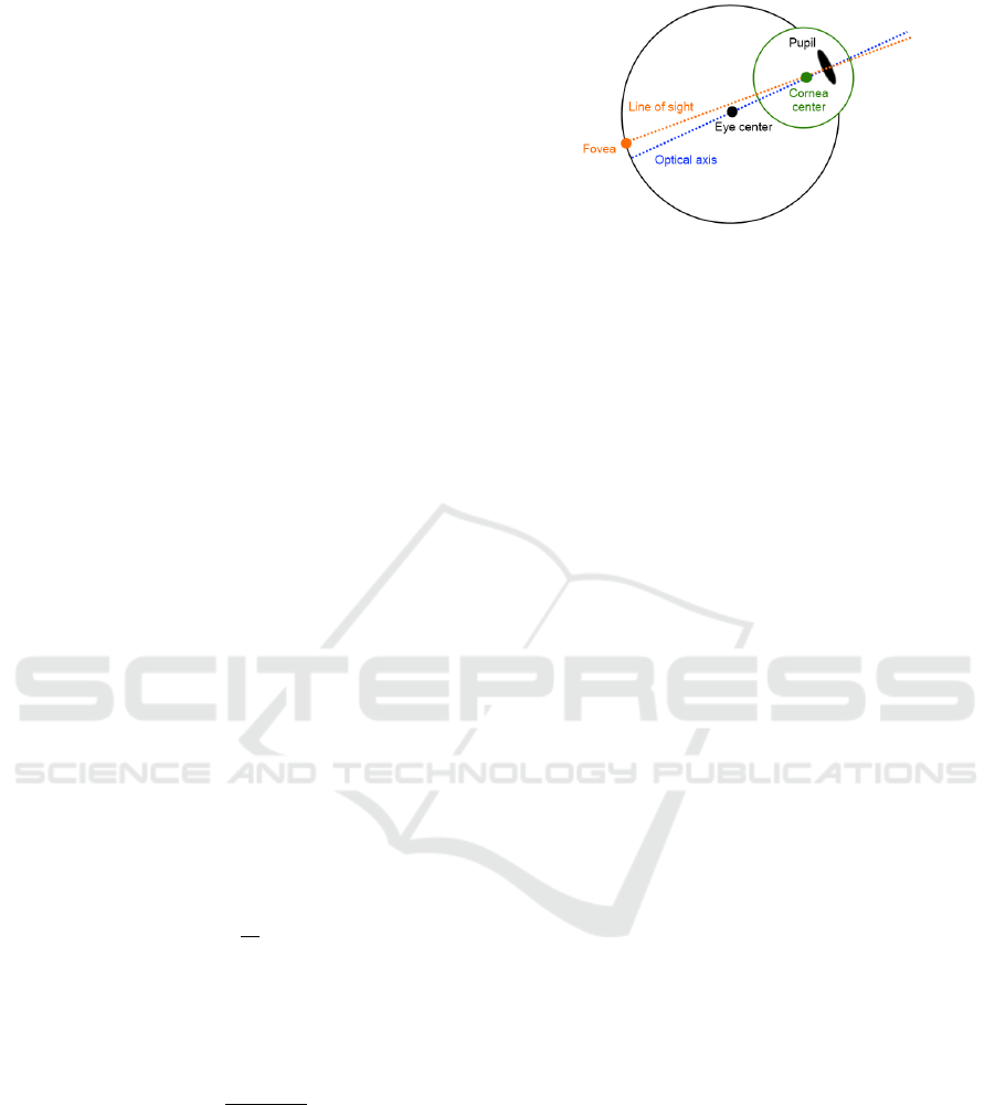
Figure 2: Optical axis vs line of sight.
measured by this method actually refers to the iris dis-
tance from the camera - as the iris centers are used
for calculations. This is as good a measurement as
any, because the face has different depths at different
places and any of them can be used for determining
head distance. A benefit of using irises is that the ex-
act 3D locations of the irises can then be calculated.
Combining this information with the gaze vector and
eye radius allows to accurately determine the eyeball
centers.
Here it should be noted that the visual axis and line
of sight are in principle two different things, as shown
in Figure 2. Eye gaze tracking systems can only mea-
sure the optical axis, whereas the actual eye gaze of a
person is determined by their line of sight. It has been
reported, that the discrepancy can be as much as 5 de-
grees (Goss and West, 2002). IR based approaches
require user specific calibration to overcome this. In
our method the initialization phase accounts for this
difference. The calculated eye center is not the true
geometrical eye center, but a central point lying on
the visual axis. Therefore, each eye gaze measure-
ment based on this initial model will inherently ac-
count for the angle between the optical axis and line
of sight. Head movements will cause certain inaccu-
racies as a different point than the true optical center
will be tracked, but these will be significant only for
very large head movements.
As has been shown, using two simple assump-
tions, the iris centers and eyeball centers can be deter-
mined in the initialization frame. In order for eye gaze
tracking to work, not only the iris needs to be found
in each consecutive frame, but the eye center loca-
tions also need to be calculated. This can be achieved
through head pose tracking, as the relative eye and
face position does not change over time. Accurate
head pose estimation is crucial for performing geo-
metric eye gaze tracking in this fashion.
2.1 Head Pose Estimation
As mentioned in (Czuprynski and Strupczewski,
2014), the most accurate head pose tracking methods
VISAPP 2016 - International Conference on Computer Vision Theory and Applications
448
are based on tracking. Despite the high accuracy of
these methods, they are vulnerable to drift and get-
ting completely lost if tracking gets lost. This in turn
would cause the entire eye gaze tracking system to
fail. Therefore, a hybrid combination of tracking and
detection is the optimal solution. When tracking fails,
redetection is performed and the head pose tracking
system recovers also removing the accumulated drift
error in the process.
To begin with head pose tracking, and also iris lo-
calisation, an approximate face position is required.
Purely detection based methods such as (Viola and
Jones, 2004) have been found to provide insufficient
accuracy. Eventually, an Active Apearance Model
(AAM) based approach was chosen. AAMs be-
gin with a coarse face position and iteratively opti-
mize the alignment of a model to fit the query im-
age (Cootes et al., 2001). More recently, more ro-
bust and efficient implementations have been pro-
posed (Matthews and Baker, 2004; Xiao et al., 2004).
We have used a proprietary implementation of these
algorithms in our eye gaze tracking system. Due to its
high efficiency, it can be run as a backgound support-
ing process to the whole eye gaze tracking system.
The AAM allows to determine the relevant face
contour, the main facial features (eyes, nose, lips) and
an estimate of the face scale and rotations. This is
crucial information for initializing the tracking algo-
rithm. We perform initialization by fitting a generic
mesh to the user’s face and later track it using opti-
cal flow or feature matching. Initially, a cylindrical
head model similar to that in (Xiao et al., 2002) was
used. Later experiments have however shown that a
more precise face model allows more accurate track-
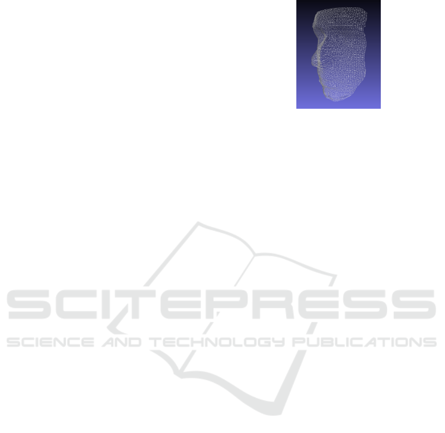
ing. Eventually, a generic facial shape was created
by recording 10 users with Kinect and averaging their
faces. It is shown in Figure 3. This person-like mesh
has demonstrated far superior performance compared
to using a cylindrical model. In general, as stated in
(Morency et al., 2008), a more accurate model that
better fits the user’s real face allows for more accurate
tracking, but also fails more quickly when drift accu-
mulates. Following this reasoning, we have modified
the algorithm further to use the AAM points for warp-
ing the generic model to the specific user’s face. This
has allowed to achieve even bigger improvement in
head pose tracking accuracy.
While a very well fitted model to the face is de-
sired, it is highly prone to drift errors. For instance,
the cylindrical model still works with roughly the
same accuracy if it drifts by three degrees of horizon-
tal rotation (the model still has the same fit quality to
the face), whereas the finely personalized model tends
to fail completely for similar discrepancies (the nose,
Figure 3: Generic face mesh.
eyes etc. all get dislocated). This high sensitivity to
drift error was the main driving factor to consider a
hybrid head pose tracking approach. In our method
we use a combination of the methods presented in
(Xiao et al., 2002; Jang and Kanade, 2004; Morency
et al., 2008; Liao et al., 2010), as described in the fol-
lowing sections.
2.1.1 Optical Flow Tracking
Our implementation of the optical flow model-based
head pose tracking algorithm closely follows the de-
scription in (Xiao et al., 2002). We use a mesh of
evenly distributed points, but having a personalized
shape instead of the shape of a cylinder. This method
works directly on image luminance. Each point of
the mesh is tracked in 2D using optical flow and all
computed point translations contribute to a rigid 6D
model transformation (3 translations and 3 rotations).
For this and further derivations it will be useful to in-
troduce some of the used notation.
Throughout this paper we use a simple pinhole
camera model where the projection is in accordance
with formula (1). Let us represent the head pose
change between frames relative to the camera as a mo-
tion vector in the twist representation:
µ = [t
x
, t
y
, t
z
, ω
x
, ω
y
, ω
z
] (3)
Where t
x
, t
y
, t
z
denote translations relative to the cam-
era and ω
x
, ω
y
, ω
z
denote rotations relative to the cam-
era. From rigid body motion theory we get that the 3D
point position at time t is given by:
P
t
= M · P
t−1
(4)
Where M is a transformation matrix based on µ:
M =
1 −ω
z
ω
y
t
x
ω
z
1 −ω
x
t
y
−ω
y
ω
z
1 t
z
0 0 0 1
(5)
Given the transformation matrix M, the projection of
P
t
can be expressed using the previous position P
t−1
and motion parametrized by vector µ:
Geometric Eye Gaze Tracking
449

p
t
=
X
t
Y
t
· f
Z
t
=
X
t−1
−Y
t−1
ω
z
+ Z
t−1
ω
y
+t
x
X
t−1
ω
y
+Y
t−1
ω
x
− Z
t−1
ω
x
+t
y
· f
−X
t−1
ω
y
+Y
t−1
ω
x
+ Z
t−1
+t
z
(6)
Let the intensity of the image at point p and time
t be denoted as I(p, t). Let F(p, µ) be a function that
maps point p into a new location p
0
using vector µ,
according to the motion model given by (6). Let the
region containing all considered face pixels be de-
noted as Ω. Computing the motion vector between
two frames based on luminance can be expressed as
the minimization of the sum of luminance differences
between the face image from previous frames and the
current face image transformed by the mapping func-
tion F:
min
∑
p∈Ω
(I (F (p, µ), t) − I (p, t − 1))
2
!
(7)
Following the original derivation in (Xiao et al.,
2002), we compute the motion vector µ using the
Lucas-Kanade method:
µ =
∑
Ω
w(I
p
F
µ
)
T
(I
p
F
µ
)
!
−1
∑
Ω
w
I
t
(I
p
F
µ
)
T
(8)
Where I
t
and I
p
are temporal and spatial image gradi-
ents, while w is a weight assigned to each point. F
µ
denotes the partial differential of F with respect to µ
at µ = 0:
F
µ
=
−XY X
2
+ Z
2
−Y Z Z 0 −X
−
Y
2
+ Z
2
XY XZ 0 Z −Z
f
Z
2
(9)
We compute motion iteratively. After each iter-
ation, the model is transformed using the computed
motion vector and the weights for all points are up-
dated. Furthermore, to handle large movements with-
out loss of accuracy, tracking is performed on a gaus-
sian image pyramid. In the original article each mesh
point was weighted by a combination of three weights
depending on the strength of the image gradient, the
density of the projected model points and the lumi-
nance difference before and after the model transfor-
mation. In our experiments we have found that the
first two do not improve tracking accuracy in a consis-
tent manner. Therefore, we only use the third weight-
ing method, which decreases the impact of points
which are not consistent with the estimated model
motion in an exponential fashion. This reduces the
impact of inaccurate alignment of the model, non-
rigid motion, illumination changes or occlusions.
We think that the presented tracking method
works better than the original mostly because of bet-
ter initialization and mesh alignment. These factors
are absolutely crucial for model-based tracking accu-
racy. Another important difference is the reinitializa-
tion method. Originally, it was proposed to save a
luminance template of the first frame and for every
frame attempt to track to this template frame - if this
is successful reinitialization is performed. In practice
this reinitialization method is not stable and often in-
troduces large random errors. We have decided to
abandon this completely in favour of a much more ac-
curate and efficient reninitialization procedure. This
is described in Section 2.1.3.
2.1.2 Feature Tracking to Template
Optical flow is one way to determine correspondences
between frames. Another, conceptually different way
is by matching feature points. Since the publica-
tion of SIFTs (Lowe, 2004), feature points have been
used extensively in many areas of computer vision.
In fact, several interesting experiments using feature
points for head pose estimation have been published,
improving the work of (Vacchetti et al., 2004). For
instance, (Jang and Kanade, 2004) propose to use
features for cylinder model based head pose estima-
tion in a framework where motion is estimated based
on matched SIFT points. The motion was estimated
between consecutive frames and to a set of stored
keyframes, integrated with the Kalman filter. More
recently, (Liao et al., 2010) propose to use intensity
based tracking (optical flow) and feature based track-
ing simultaneously and weight them according to the
tracking error. We have implemented continuous fea-
ture based pose estimation and found that it is very
prone to drift - in fact much more than optical flow
methods. On the other hand, features can be detected
independently in each frame, which means that there
is no drift error in the matched features themselves.
This is an important advantage when considering the
reinitialization concept. Eventually, it turned out that
feature based head pose estimation is the ideal method
for tracking to template frames (keyframes) for reini-
tialization purposes.
Let us introduce the concept of pose estimation
based on local features. Let us assume that two in-
dependent sets of feature points are detected in two
facial images. Let us assume further that a subset
of these points was matched to form pairs (p
t−1
, p
t
).
The points from the first frame are related to a known
head pose, so their 3D coordinates, P
t−1
, are known.
Therefore, two forms of point coordinates in the sec-
ond image are available. The first are the observed
locations of the detected points p
t
. The second form
are the projections p
0
t
of the points P
0
t
, obtained by
estimating the motion of the previous locations P
t−1
based on the 3D model and motion vector µ. Assum-
VISAPP 2016 - International Conference on Computer Vision Theory and Applications
450
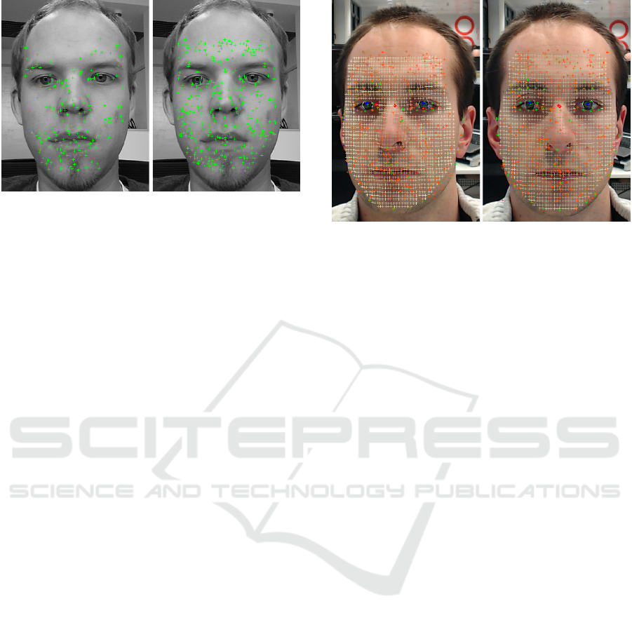
Figure 4: Left image shows SIFT features, right image
shows STAR features.
ing N such point pairs have been collected, the goal
is to compute motion vector µ, which minimizes the
sum of distances between the observed points p
i,t
and
the estimated points p
0
i,t
. It can be achieved by solv-
ing the following equation set using the linear least
squares method:
p
0,t
− p
0
0,t
= 0
.
.
.
p
N,t
− p
0
N,t
= 0
(10)
Where the estimated points are given by:
p
0
i,t
=
P
0
i,t
PROJ
= [M · P
i,t−1
]
PROJ
(11)
Although first results of the above algorithm were
promising, we have found that SIFT points are not
ideally suited for usage with faces. Faces contain few
corner points and are unlike the typical scenes that
SIFT points were designed for. After testing various
point detectors we have found that the best results are
achieved when using the STAR feature detector with
a low detection threshold. A comparison of SIFT and
STAR detectors is shown in Figure 4.
As the feature descriptor we have decided to use
BRISK (Leutenegger et al., 2011). This is because it
is lightweight, robust and free to use. The accuracy
of the final feature based head pose tracking algo-
rithm was above expectations. All head poses within
the range of at least 10 degrees from a frontal pose
could be correctly estimated using a single template.
For small rotations it was impossible to visually ob-
serve any inaccuracy when analysing the mesh. This
is shown in Figure 5.
2.1.3 Hybrid Algorithm
The work of (Morency et al., 2008) proposes to
combine differential tracking, keyframe tracking and
static pose estimation using the Kalman filter. The
Figure 5: Feature tracking to single frontal template.
Kalman filter is also used in (Jang and Kanade,
2004). Each of these algorithms relies on multiple
keyframes, which are collected while the algorithm
is running. This contributes to a nice visual effect,
but unfortunately deteriorates tracking accuracy. Any
form of collecting templates with drift is bound to
increase the overall tracking error, despite improv-
ing the robustness of the system. This can be seen
if one looks closely at the videos available at Takeo
Kanade’s website (Jang and Kanade, 2010).
In the use case of eye gaze tracking we have eval-
uated two approaches:
• Online collecting of multiple separate templates
with features for various head poses
• Online growing of a single template with features
from many frames, with feature points aligned to
form a single 3D model
In the first case each template that was collected while
the system was running contained a certain drift. Un-
fortunately for the eye gaze tracking scenario, using a
template with drift has negative consequences. All in
all, this approach has worsened the eye gaze tracking
algorithm accuracy, especially in case of large head
movements. The improvement in robustness does not
compensate sufficiently for the deterioration.
In the second case the idea was to combine the
3D mesh warped during initialization with new fea-
tures detected in later frames. This can be important
as when the user rotates their head, different feature
points become visible than in the frontal pose. Thus, a
single composite model can be formed with all points
aligned according to how the 3D model was tracked
over time. In principle this approach suffers from the
same drift error as the previous one, except the drift
error is only associated with the additional features
added to the composite model. If very accurate track-
ing is performed, the drift error can be very small and
Geometric Eye Gaze Tracking
451

the additional points collected over time improve the
robustness of the system (there are more points than
in the case of a single template). However, if the
points are added during less accurate tracking, they
have a negative impact. In practice, we have found
that when only points from a frontal pose are added to
the model, when very little or no head movement has
been made since initialization, it improves the track-
ing system. Because the camera sensor is noisy, even
frames with exactly the same pose can contain up to
25% different feature points.
The second described strategy can sometimes sig-
nificantly improve tracking robustness, although it is
highly dependant on the initialization and the shape
of the user’s face. Nonetheless, as the most accu-
rate method available, it has been chosen as the ba-
sic tracking mode. We have found a good strategy to
be growing an aggregate template using 5 to 10 initial
frames. After this, feature and optical flow model-
based tracking are performed simultaneously for each
new frame. The tracking method that gives smaller
error is chosen. Typically, for poses very close to the
initial pose feature tracking will outperform optical
flow tracking, whereas for other poses, when few fea-
tures can be matched to the initial template, optical
flow will provide much better accuracy. When one of
the methods gives a very large error compared to the
other one, it is simply discarded. The error is calcu-
lated as the luminance difference between the mesh
points before and after the transformation.
One more thing that should be mentioned here is
usage of the AAM. It is a third algorithm running vir-
tually all the time. Its main role is guidance in the
case of reinitialization - when all other tracking fails.
Reinitialization can be performed by using the face
location based on the AAM output and calculating
feature points. These feature points are then matched
to those of the stored face template. Once the relative
pose to the stored template is known, the 3D mesh can
be reinitialized and tracked using the hybrid tracking
algorithm described above.
2.2 Iris Localisation
We use eye regions extracted by the AAM algorithm
to search for the iris. We have found that the best
iris detection accuracy is achieved in a dual approach
consisting of two stages. The first stage aims to per-
form coarse localisation and is based on the Hough
transform. The second stage provides a refinement
based on Circular Integro Differential Operator. Our
approach is partly similar to (Zhou et al., 2011). Each
stage will be described in the following sections.
2.2.1 Coarse Iris Localization
Coarse iris estimation is based on a voting technique.
The approach is very similar to the Circle Hough
Transform (CHT). It is based on the assumption, that
the iris bound is a transition between a bright outside
region and a dark inside region of the iris. The exact
radius of the eye is unknown, but its potential range
can be estimated based on the face size in pixels. Only
right and left iris boundary pixels are considered, be-
cause the upper and lower bounds can be occluded by
the skin around the eye. As a result, assuming that
the face is upright, only edges that have a vertical di-
rection (first order derivative angle direction is larger
than 45 degrees) are considered.
The algorithm works as follows. First, the rele-
vant image region is prepared and first order deriva-
tives are computed for each pixel. Every pixel is anal-
ysed and if the gradient is strong enough and verti-
cal enough, it votes for the iris center according to
the gradient direction and currently analysed radiuses.
Several passes of the algorithm are completed for var-
ious radii. The voting bins are later blurred by a Gaus-
sian kernel and the maximum among pixel locations
and radii is chosen as the rough iris center position.
To provide additional robustness, we weight the voted
centers with the inverse of the region’s brightness.
This favours dark regions, such as the pupil should
be, and helps to prevent misdetections.
2.2.2 Fine Iris Localization
Fine localization of the eye center is based on Daug-
man’s integro-differential operator. Similarly as in
the original publication (Daugman, 2002), a set of
ellipses is matched with the iris contour in order to
maximize the sum of Daugman’s circular integro-
differential operator:
max
(r,x
c
,y
c
)
G
σ
(r) ?
∂
∂r
ˆ
r,x
c
,y
c
I(x , y)
2πr
ds
(12)
Where I(x, y) is the gray level of the image and
G
σ
(r) is the Gaussian smoothing filter. The operator
searches over the iris image domain (x, y) for the
maximum change in pixel values, with respect to
increasing radius r along a circular ds of radius r and
center coordinates (x
c
, y
c
). To achieve a speed up, the
algorithm is performed in a coarse to fine fashion -
the used 4r, 4x, 4y are larger in the first stage, and
smaller in later stages. Altogether three stages are
used, which provides optimum efficiency with the
desired accuracy.
VISAPP 2016 - International Conference on Computer Vision Theory and Applications
452
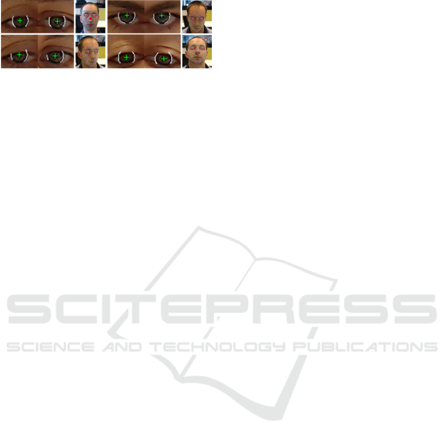
Figure 6: Adaptive iris localisation.
2.2.3 Adaptive Behaviour
In order to reduce the influence of eyelids, eyelashes
and other skin parts we only consider vertical parts
of the iris when calculating the radial sum in equation
(12). However, this is not accurate enough, as depend-
ing on the person and where they are looking, differ-
ent parts of the iris are visible. Therefore, we ignore
a certain percentage of the gradient lying on the circle
depending on gradient strength. Thus, only a subset
of the vertical gradients is used for calculations. What
is more, an analysis of the relation between the look-
ing direction and visible iris contours has shown that
the correlation is very strong. We have therefore de-
veloped an adaptive version which considers the eye
gaze and head pose of the person in order to optimally
select which parts of the iris should be used for cal-
culations. Figure 6 shows which parts of the iris are
chosen for refinement depending on the eye rotation
relative to the head.
We propose to use the following methodology.
Traditionally, only vertical iris boundaries are con-
sidered - this means half of all the points. To deter-
mine which points to use, a top and bottom boundary
threshold can be established. Furthermore, the left
and right side of the iris can require different treat-
ment, as is shown in Figure 6. Therefore, for each
side of the iris, left and right iris boundary thresholds
can be established. This gives altogether four angu-
lar thresholds: left top, left bottom, right top and right
bottom. We propose to adjust these thresholds accord-
ing to head rotations and gaze directions, as follows:
θ
lt
= θ
lt
(1 + α
l
· (gx − rx ) + β
t
· (gy − ry))
θ
lb
= θ
lb
(1 + α
l
· (gx − rx ) + β
b
· (gy − ry))
θ
rt
= θ
rt
(1 + α
r
· (gx − rx ) + β
t
· (gy − ry))
θ
rb
= θ
rb
(1 + α
r
· (gx − rx ) + β
b
· (gy − ry))
(13)
Where rx, ry are head rotations and gx, gy are gaze
angles in the horizontal and vertical planes. The pa-
rameter values of α
l
, α
r
, β
t
, β
b
have been chosen ex-
perimentally based on the available test sequences.
An evaluation of the described algorithm was per-
formed on a manually tagged set of webcam images
and is described in section 3.
2.3 Mutual Head Pose and Iris Relation
In our eye gaze tracking system the iris positions are
used to refine the head pose estimation. This is done
during initialization. As was mentioned in Section
2.1, the head distance from the camera along the z
axis has to be estimated in the first frame. For this,
the distance between the eyes is used, and this can
be most accurately measured as the distance between
the irises. What is more, the irises are used as refer-
ence points for aligning and warping the mesh during
initialization. No facial feature can be detected as ac-
curately as the irises, so this strategy is the best. A
better aligned mesh at the beginning of tracking leads
to better results.
At the same time, the head pose is used to refine
iris localisation. First of all, the head pose determines
the regions which are used for iris searches. The re-
gions can be determined by AAM points, or taken
from the mesh directly if the AAM is not used in every
frame. Secondly, once the eye gaze vector is known,
it is the head pose that determines which parts of the
iris contours are visible in the image. This informa-
tion is used directly in the adaptive refinement stage
as described in Section 2.2.3.
2.4 Calibrating Eye Depth and Head
Size
It has earlier been mentioned that the proposed system
makes the assumption of a typical eye radius (12mm)
and face size (6cm between irises) for each person
unless configured otherwise. While the distance be-
tween the eyes can be quite easily measured manually
by the user with a ruler, the eye radius, and so eye cen-
ter depth relative to the iris, is impossible to measure
explicitly. Both of these unknown values can be mea-
sured automatically. Let us assume that the user is
looking at a known point in several different frames
and moves their head. Let us assume further, that the
head pose can be tracked with at least basic accuracy,
based on the generic face size assumption and mesh
tracking as described in Section 2.1.1. In all those
frames, the irises are detected, and the gaze point is
known. Therefore, the gaze vector is known. What
remains unknown is the eye center location. But, for
each frame it has to lie somewhere along the gaze vec-
tor. If the head pose transformation is known from the
head pose tracking algorithm, a set of equations can
be formed to find this unknown eye depth:
M
0
· P
eye
= λ ·
−→
g
0
.
.
.
M
n
· P
eye
= λ ·
−→
g
n
(14)
Geometric Eye Gaze Tracking
453
Where M
i
is the current estimation of the head pose,
P
eye
is the 3D eye center position in head-relative co-
ordinates,
−→
g
i
is the gaze vector and λ is a scaling fac-
tor that stretches a unit gaze vector from the camera
to the eye center. The above applies to the situation
when the user is looking straight at the camera. For
other gaze points the formulas get more complicated,
but the concept remains the same.
As the eye location is the same in head-relative co-
ordinates, the gaze vectors and head pose transforma-
tions are the only variables that change. The scaling
factor λ only depends on the face distance from the
camera, and so its relative change is also assumed to
be known from head pose tracking. This means that a
set of at least two equations allows to find the true 3D
eye location along with the scaling factor λ. In prac-
tice, at least several measurements should be used to
reduce the measurement error. If many measurements
are available, one may assume that the z distance in M
is unknown, and calculate it together with the relative
eye depth. Thus, the face size can be established with-
out the need to measure it with a ruler.
In practice, the described calibration method
works well only when the calibration data is of high
quality. As the calibration depends on the user and
lighting conditions, we have opted to leave this as an
option and not use it as an integral part of our system.
3 EXPERIMENTS
We have performed multiple evaluations of the eye
gaze tracking components - head pose tracking and
iris tracking. We believe that both presented head
pose tracking and iris tracking algorithms are in the
state-of-the-art category. To remain concise, we
present only the measured accuracy of the whole eye
gaze tracking system.
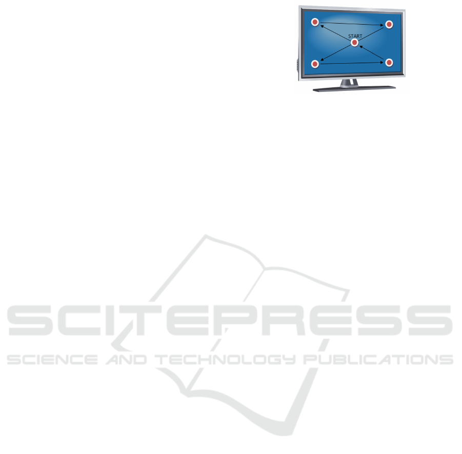
3.1 Test Framework
To evaluate the performance of the developed algo-
rithms we have created a dedicated, novel test frame-
work. It works on recorded test sequences and is
able to measure the difference between the real place
where the user is looking and the estimation given by
the system. The test sequences are recorded by dis-
playing a point on the screen and asking the user to
look at it. We propose to use two stages: one with a
motionless head and one with head movements. This
allows to identify the weaknesses of the algorithm
easier. During the phase without head movements,
the marker is shown in the center of the screen during
initialization and moves near the four screen corners,
Figure 7: Locations where the user has to look during a test
sequence.
but leaving a margin of 7.5% of the screen width and
height from the exact corners. During the phase with
head movements, the marker is placed in the screen
center, so the system measures simply how robust the
algorithm is in terms of head movement compensa-
tion. Figure 7 shows exactly how the test points were
shown on the screen and in which order.
When the test point was moving between the five
states on the screen, the gaze calculation error was not
measured. Thus, any inaccuracy resulting from delays
was not considered.
In order to evaluate the system, we have prepared
10 test sequences with different people using a simple
1080p webcam. Each sequence was recorded for 15
seconds at a 15 fps frame rate. This means that each
test sequence consists of around 225 frames. Figure 8
shows what kind of head movements were performed.
Additionally to measuring the point of regard of
the user, the head pose tracking accuracy and iris
tracking accuracy can be compared with manually
tagged ground truth. We have developed a tagging ap-
plication that allows to tag the iris centers, inner and
outer eye corners and lip corners. This can be tagged
for every frame. When tracking and iris localisation
is performed, the facial features tagged in the first
frame and consecutive frames can be compared and
any discrepancies measured. Of course, if ideal track-
ing was performed, the tracked features from the first
frame would coincide with tagged features in other
frames. We have been able to measure average errors
of tagged facial features less than one pixel, but such
measurements do not say much as the manual tagging
is of limited accuracy. It is slightly easier to tag the
iris, especially with our radial fitting tool, that allows
to place a circle of variable size over the magnified
iris image. We have measured an average iris detec-
tion error below 0.85 pixel for low-quality image se-
quences having 100 pixels between the eyes, and an
average error below 0.7 pixel for high quality image
sequences having 150 pixels between the eyes. Fig-
ure 9 shows these results obtained from tagged test
sequences.
VISAPP 2016 - International Conference on Computer Vision Theory and Applications
454
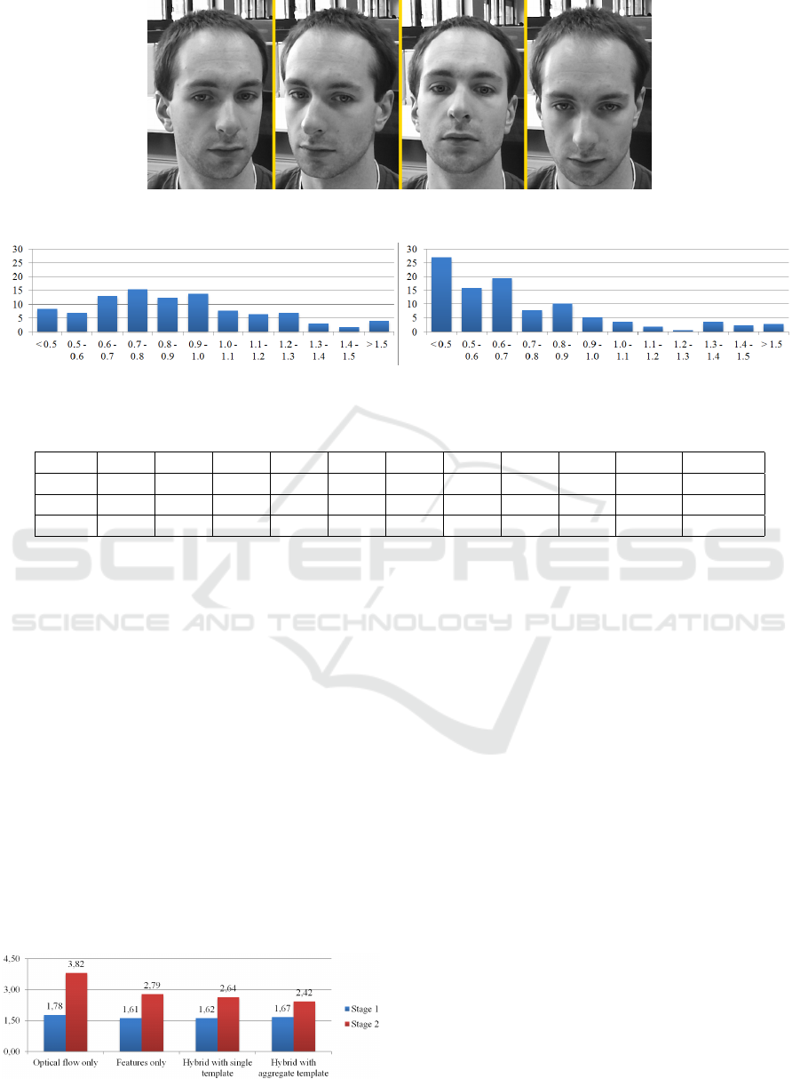
Figure 8: Illustration of head movements performed during test recording.
Figure 9: Percentage of iris images localized with an error within given pixel range. Left: Low quality data. Right: High
quality data.
Table 1: Webcam eye gaze tracking results for hybrid mode [degrees].
Stage Seq1 Seq2 Seq3 Seq4 Seq5 Seq6 Seq7 Seq8 Seq9 Seq10 Average
1 0.91 0.74 1.06 2.32 2.95 2.79 3.09 1.80 1.78 0.87 1.67
2 1.78 1.82 5.51 2.62 2.31 2.88 1.45 1.56 3.20 3.48 2.42
total 1.30 1.24 3.45 2.48 2.68 2.83 2.27 1.67 2.50 2.05 2.25
3.2 Test Results
The test results for the optimal hybrid head pose
tracking mode with aggregate template usage and
adaptive iris localisation as described in Section 2.2.3
are shown in Table 1. We have measured the angular
errors between ground truth and measured gaze di-
rections. In the test sequences, the user was seated
around 70cm away from the display. The display that
we used is 51cm wide.
As can be noticed in Table 1, the results for the
second phase when the head is moving are signifi-
cantly worse. This is quite understandable, as during
the first phase virtually no head movement analysis is
required. Furthermore, it is clear that the results are
significantly different for each sequence. This sug-
gests that the generic mesh has different alignment
Figure 10: Eye gaze tracking algorithm accuracy compari-
son - POR error [degrees].
errors for each user despite user specific warping at
initialization. Perhaps an even more accurate initial-
ization procedure could help, such as usage of a depth
camera. Another possible reason for the discrepan-
cies among results are the iris characteristics causing
different behaviour of the iris detection algorithm for
each person. We have noticed a high sensitivity of
to this algorithm to user appearance, especially in the
vertical plane.
Apart from the best achieved results, we would
like to present the improvement achieved when using
hybrid head pose tracking compared to using a sin-
gle tracking method. Figure 10 compares the mean
absolute errors between the different tracking config-
urations.
The hybrid method is clearly better than any single
tracking method. A further interesting observation is
that the aggregate template mode is slightly less accu-
rate than the corresponding mode with a single tem-
plate (larger error in stage one), but much more ro-
bust to head movements (smaller error in stage two).
All the measured errors result from two factors: A
slightly inaccurate eye model (which is person spe-
cific) and inaccuracies in tracking the eyeball center
with the head - so in fact inaccuracies of head pose
tracking.
Geometric Eye Gaze Tracking
455

In comparison to other leading researches on the
topic of webcam eye gaze tracking (Ishikawa et al.,
2004; Kim and Kim, 2007; Valenti et al., 2012), we
have demonstrated that our system achieves better ac-
curacy. An average error of 2.25 degrees measured
with significant head movements is better than other
systems reporting an accuracy between 3 and 5 de-
grees.
4 CONCLUSIONS
We have presented a novel eye gaze tracking method
that requires only webcam quality RGB images.
We have demonstrated that this method performs
favourably to other systems presented in literature.
We believe that extending the idea further with more
accurate sensor readings, such as a depth sensor, can
lead to an even more accurate eye gaze tracking al-
gorithm which will be used in commercial systems in
the near future.
A further advantage of our approach is its capa-
bility to run in real time on contemporary mobile de-
vices. We have ported the algorithm to the Galaxy S4
smartphone and were able to obtain a speed of 15 fps
at a camera resolution of 640x480 pixels, when the
user was approximately 40cm away from the smart-
phone.
REFERENCES
Cootes, T. F., Edwards, G. J., and Taylor, C. J. (2001). Ac-
tive appearance models. IEEE Trans. Pattern Anal.
Mach. Intell., 23(6):681–685.
Czuprynski, B. and Strupczewski, A. (2014). High accu-
racy head pose tracking survey. In Active Media Tech-
nology, volume 8610 of Lecture Notes in Computer
Science, pages 407–420. Springer International Pub-
lishing.
Daugman, J. (2002). How iris recognition works. IEEE
Transactions on Circuits and Systems for Video Tech-
nology, 14:21–30.
Dodgson, N. A. (2004). Variation and extrema of human
interpupillary distance.
Goss, D. A. and West, R. (2002). Introduction to the optics
of the eye. Butterworth-Heinemann.
Hansen, D. W. and Ji, Q. (2010). In the eye of the beholder:
A survey of models for eyes and gaze. IEEE Trans.
Pattern Anal. Mach. Intell., 32(3):478–500.
Hennessey, C., Noureddin, B., and Lawrence, P. (2006). A
single camera eye-gaze tracking system with free head
motion. pages 87–94.
Ishikawa, T., Baker, S., Matthews, I., and Kanade, T.
(2004). Passive Driver Gaze Tracking with Active Ap-
pearance Models. Technical Report CMU-RI-TR-04-
08, Robotics Institute, Carnegie Mellon University,
Pittsburgh, PA.
Jang, J. and Kanade, T. (2004). Robust 3d head tracking by
online feature registration.
Jang, J.-S. and Kanade, T. (2010). Robust 3d head tracking
by view-based feature point registration. Available at
www.consortium.ri.cmu.edu/projCylTrack.php.
Kim, J.-T. and Kim, D. (2007). Gaze Tracking with Active
Appearance Models. Technical report, Department of
Computer Science and Engineering, Pohang Univer-
sity of Science and Technology.
Leutenegger, S., Chli, M., and Siegwart, R. Y. (2011).
Brisk: Binary robust invariant scalable keypoints. In
Proceedings of the 2011 International Conference on
Computer Vision, ICCV ’11, pages 2548–2555, Wash-
ington, DC, USA. IEEE Computer Society.
Liao, W.-K., Fidaleo, D., and Medioni, G. (2010). Robust:
Real-time 3d face tracking from a monocular view. J.
Image Video Process., 2010:5:1–5:15.
Lowe, D. G. (2004). Distinctive image features from scale-
invariant keypoints. Int. J. Comput. Vision, 60(2):91–
110.
Lu, F., Okabe, T., Sugano, Y., and Sato, Y. (2014). Learning
gaze biases with head motion for head pose-free gaze
estimation. Image and Vision Computing, 32(3):169 –
179.
Matthews, I. and Baker, S. (2004). Active appearance mod-
els revisited. Int. J. Comput. Vision, 60(2):135–164.
Morency, L., Whitehill, J., and Movellan, J. (2008). Gen-
eralized adaptive view-based appearance model: In-
tegrated framework for monocular head pose estima-
tion. pages 1–8.
Ohno, T., Mukawa, N., and Yoshikawa, A. (2002).
Freegaze: A gaze tracking system for everyday gaze
interaction. pages 125–132.
Riordan-Eva, P., Whitcher, J., Vaughan, D., and Asbury,
T. (2004). Vaughan & Asbury’s General Ophthal-
mology. A Lange medical book. Lange Medical
Books/McGraw Hill Medical Pub. Division.
Vacchetti, L., Lepetit, V., and Fua, P. (2004). Stable real-
time 3d tracking using online and offline informa-
tion. Pattern Analysis and Machine Intelligence, IEEE
Transactions on, 26(10):1385–1391.
Valenti, R., Sebe, N., and Gevers, T. (2012). Combining
head pose and eye location information for gaze es-
timation. Image Processing, IEEE Transactions on,
21(2):802–815.
Valenti, R., Staiano, J., Sebe, N., and Gevers, T. (2009).
Webcam-based visual gaze estimation. In Foggia, P.,
Sansone, C., and Vento, M., editors, Image Analysis
and Processing - ICIAP 2009, volume 5716 of Lecture
Notes in Computer Science, pages 662–671. Springer
Berlin Heidelberg.
Viola, P. and Jones, M. J. (2004). Robust real-time face
detection. Int. J. Comput. Vision, 57(2):137–154.
Wood, E. and Bulling, A. (2014). Eyetab: Model-based
gaze estimation on unmodified tablet computers. In
Proceedings of the Symposium on Eye Tracking Re-
search and Applications, ETRA ’14, pages 207–210,
New York, NY, USA. ACM.
VISAPP 2016 - International Conference on Computer Vision Theory and Applications
456

Xiao, J., Baker, S., Matthews, I., and Kanade, T. (2004).
Real-time combined 2d+3d active appearance models.
pages 535–542.
Xiao, J., Kanade, T., and Cohn, J. F. (2002). Robust full-
motion recovery of head by dynamic templates and
re-registration techniques.
Zhang, W., Li, B., Ye, X., and Zhuang, Z. (2007). A robust
algorithm for iris localization based on radial symme-
try. pages 324–327.
Zhou, Z., Yao, P., Zhuang, Z., and Li, J. (2011). A robust al-
gorithm for iris localization based on radial symmetry
and circular integro differential operator. pages 1742–
1745.
Geometric Eye Gaze Tracking
457
