
Visual Navigation with Street View Image Matching
Chih-Hung Hsu
1
and Huei-Yung Lin
2
1
Department of Electrical Engineering, National Chung Cheng University,
168 University Rd., Chiayi 621, Taiwan
2
Department of Electrical Engineering, Advanced Institute of Manufacturing with High-Tech Innovation,
National Chung Cheng University, 168 University Rd., Chiayi 621, Taiwan
Keywords:
Visual Navigation Assistance, Image Matching, Panoramic Image.
Abstract:
The vision based navigation approach is a key to success for the driving assistance technology. In this work,
we presents a visual navigation assistance system based on the geographic information of the vehicle and
image matching between the online and pre-established data. With the rough GPS coordinates, we utilize the
image retrieval algorithms to find the most similar image in the panoramic image database. The searching
results are then compared with the input image for feature matching to find the landmarks in the panoramic
image. By using the 360
◦
field-of-view of the panoramic images, the camera’s heading can be calculated by
the matching results. Finally, the landmark information is identified by the markers on the Google map as
visual guidance and assistance.
1 INTRODUCTION
The navigation techniques based on visual informa-
tion are getting more and more popular in recent
years. When people are in an unknown or unfamiliar
environment, visual navigation plays a key role to the
movement guidance. In general, landmarks are the
most reliable visual cues for the perception of outdoor
scenes. Using landmarks as references is very obvi-
ous to understand where you are and where do you
want to go. In the traditional navigation systems, a
number of available landmarks are tagged on the map
and their images are provided for location identifica-
tion. Since the landmarks may appear differently ob-
served from different viewing directions, scene recog-
nition becomes a nontrivial task if the images are cap-
tured perspectively from a single viewpoint.
Currently, it is still not possible to achieve the
fully autonomous navigation due to various techni-
cal difficulties. Thus, many researchers are devoted
themselves to the assisted technologies for naviga-
tion. The previous work on the development of as-
sisted navigation techniques is generally divided to
two categories for the indoor and outdoor applica-
tions. In the indoor case, Saab et al. use the radio
frequency identification device (RFID) for localiza-
tion (Saab and Nakad, 2011). Several passive tags
are pre-installed in the indoor environment, and the
RFID device can retrieve the information from the
tags when a user gets close to those places. Mulloni
et al. utilize the image marker to encode the infor-
mation in the proposed system (Mulloni et al., 2009).
The users can use their cell phones to capture and de-
code the markers to determine the locations. Huang et
al. present a vision based self-localization technique
for mobile robot applications (Huang et al., 2012). A
camera is used to capture the images of pre-installed
2D barcode patterns on the ceiling for indoor local-
ization. The above approaches require structured or
controlled environments to derive the location infor-
mation and therefore are not suitable for the outdoor
applications.
For the outdoor navigation, a primary information
source can be obtained from the images of the scenes.
The images are capable of providing the visual assis-
tance close to the human perception while not alter-
ing the environment. There have been many tech-
niques developed to construct the object classifiers
(i.e., trees, cars, buildings, roads, pedestrian, etc.) and
used to process the input scene images for the deriva-
tion of semantic maps. The most likely scenes in the
image database are then identified according to the
semantic maps (Wang et al., 2015; Yao et al., 2014;
Siddiqui and Khatibi, 2014). Some researchers as-
sume that the users are able to capture the most repre-
sentative objects such as buildings and define them as
landmarks. The navigation system is designed to use
the input image to match and find the related land-
Hsu, C-H. and Lin, H-Y.
Visual Navigation with Street View Image Matching.
DOI: 10.5220/0005674405830589
In Proceedings of the 11th Joint Conference on Computer Vision, Imaging and Computer Graphics Theory and Applications (VISIGRAPP 2016) - Volume 3: VISAPP, pages 585-591
ISBN: 978-989-758-175-5
Copyright
c
2016 by SCITEPRESS – Science and Technology Publications, Lda. All rights reserved
585

mark image and return the corresponding information
to the users. Two commonly adopted methods, in-
cluding image retrieval and landmark matching, are
briefly reviewed as follows.
The image retrieval approach is based on the im-
age features like texture, line, shape, etc. Turcot et al.
use the bag-of-words to construct an image database,
and choose the most useful features for image re-
trieval (Turcot and Lowe, 2009). Philbin et al. adopt
the random tree to construct the relationship between
the image and the image features, and then use it for
image retrieval (Philbin et al., 2007). Hu et al. pro-
pose a gradient field HOG (GF-HOG) technique. The
users sketch the shapes of objects and the system can
extract the GF-HOG features to perform the image
retrieval (Hu and Collomosse, 2013). In the recent
years, the GPS system is extensively used in many
applications. Some researches also utilize the GPS
data to increase the accuracy of image retrieval (Chen
et al., 2011; Altwaijry et al., 2014; Zamir and Shah,
2010; Liu et al., 2012).
In the landmark matching techniques, Naoyuki et
al. use SURF (Speeded Up Robust Features) (Bay
et al., 2008) to perform image matching between the
panoramic and perspective images (Uchiyama et al.,
2009). However, due to the 360-degree field-of-view
(FOV) of the panoramic images, good results can-
not be achieved using the traditional image features
(Lin et al., 2013). Chen et al. crop the landmarks in
the panoramic image to many blocks, calibrate these
sub-image blocks, and then use these sub-images to
match with the input image (Chen et al., 2011). Sim-
ilarly, the traditional 2D orientation descriptor such
as SIFT (Scale Invariant Feature Transform) is also
unsuitable for panoramic image because of the image
distortion and camera rotation (Lowe, 2004). Ben-
jamin et al. propose a 3D orientation SIFT and use it
to improve the matching results for panoramic images
(Resch et al., 2014).
In the past few years, Google Map Street View
could be the most famous image guided navigation
system. The users only need to input theirs GPS co-
ordinates, and the system will quickly return the loca-
tions on the map and the surrounding 360-degree im-
ages. Since the GPS accuracy is occasionally affected
by the weather condition and other factors, the users
should manually check the images are correct or not.
In this work, we present a visual navigation assistance
system. The user only have to input a landmark image
and the nearby GPS coordinates, the proposed navi-
gation system is able to return the name of the identi-
fied landmark. Due to the advances of smart wearable
devices, it becomes possible to obtain the GPS en-
abled images easily. Our navigation assistance tech-
Figure 1: An overview of the proposed visual navigation
assistance framework.
nique utilizes the image and geographical information
to search in the panoramic image database. Since the
panoramic image contains 360
◦
FOV, the matching
result can be used to calculate the heading of the im-
age capture orientation. The corresponding landmark
marker is then obtained by searching the Google map
images with the heading angle.
2 PROPOSED FRAMEWORK
The proposed framework consists of three stages: (i)
image retrieval from the panoramic image database,
(ii) image matching between the perspective and
panoramic images, (iii) calculation of the camera
heading and using the angle to search the landmark
marker on the Google Map. The overview of our sys-
tem is shown in Figure 1. We will describe the method
used in detail below.
2.1 Database and Image Retrieval
In the proposed navigation technique, several image
databases are first recorded in different regions. Each
image database consists of panoramic images and the
associated geographical coordinates. For testing or
vehicle localization, we capture the perspective im-
ages using a conventional camera and also record the
geographical information around the regions. The test
images are acquired with the landmarks we are inter-
ested for navigation assistance.
For an input perspective image, our navigation
system should identify the most similar panoramic
image in an image database. Since our database con-
tains images and the associated geographical coordi-
nates, there are two simple ways to perform the image
retrieval– using either the image based techniques or
the GPS information. These two methods, however,
both have some drawbacks. First, using the image
VISAPP 2016 - International Conference on Computer Vision Theory and Applications
586

Figure 2: The nodes assigned by the images in the database.
based technique alone will require a lot of search-
ing time since there usually have many street scene
images in the database. Second, the GPS informa-
tion is not always reliable because it may be affected
by some factors, such as bad weather conditions, tall
building, tunnel, etc.
Our navigation assistance technique combines the
image based approach and geographical coordinates
to construct the image retrieval system. We capture
the panoramic images on the left and right lanes along
a road for every 13 meters. A node is assigned to 6
neighboring panoramic image capture locations as il-
lustrated in Figure 2. The nodes of 6 images plus 2 ad-
ditional ones in the front and 2 additional ones in the
back are used for image retrieval and there is no need
to record the GPS coordinates for each panoramic im-
age. Given an input image, its location will be associ-
ated with a nearest node which is verified by feature
matching on the panoramic images in the database.
In the previous research, it is shown that SIFT
outperforms other features (Juan and Gwun, 2009).
When the 10 candidate panoramic images are found,
the number of SIFT matching points is considered as
the similarity measure between the panoramic and in-
put images. We extract the SIFT feature points in the
input image and 10 candidate panoramic images. The
features of candidate images are merged to a feature
vector
F = { f
1
, f
2
, f
3
, f
4
, f
5
, f
6
, f
pre1
, f
pre2
, f
back1
, f
back2
}
The feature vector F is used to match with the input
image feature f
I
. A score is given to each panoramic
image according to the number of matching feature
points. The panoramic image which has the highest
score is the most similar to input image. Mathemati-
cally, it can be written as
{S
1
, . . . , S
6
, S
pre1
, S
pre2
, S
back1
, S
back2
} = M( f
I
, F)
I
r
= argmaxM( f
I
, F)
where I
r
is the retrieved panoramic image.
(a) (b)
(c) (d)
Figure 3: The image segmentation to separate the sky and
landmark regions. (a) The original image. (b) The edge
image obtained by Canny edge detection. (c) The result
from dilation and erosion. (d) The segmentation result by
the FloodFill algorithm.
2.2 Landmark Matching
Although the most similar image is found in the im-
age retrieval stage, the system still does not know
the corresponding landmark in the panoramic im-
age. The SIFT features are commonly used for land-
mark matching, but the results we find are generally
not good enough. There always exist some incor-
rect matching points. Since the landmarks of inter-
ests usually contain regular appearance, we add land-
mark contour line features to enhance the correctness
of SIFT feature matching. It is the common case that
the landmarks in the images are connected with the
sky. Thus, the landmark contour lines can be ob-
tained by separating the sky region from the fore-
ground. We use the segmentation method proposed
by Laungrungthip et al. (Laungrungthip et al., 2008).
Canny edge detection (Canny, 1986) is first applied
to extract the line segments, followed by the dila-
tion and erosion operations to fill the gaps in broken
edges. The FloodFill algorithm is then carried out to
fill the region from the top of the image (Hughes et al.,
2013). Finally, the landmarks are separated from the
sky by the contour lines detected by Hough transform
(Hough, 1962).
In the outdoor scenes, the captured images usu-
ally contain a lot of trees and leaves. These objects
should be treated as noise because it will cause un-
reliable landmark matching. In general, the line seg-
ments associated with trees and leaves have smaller
length and the most representative line segments have
longer length. According to this property, the noise is
filtered out by comparing the length of line segments.
We can then choose the longest line segments at dif-
ferent angles to be the most representative ones. The
generation of line segments is based on the fact that
Visual Navigation with Street View Image Matching
587

Figure 4: The ROI setting for the feature descriptor con-
struction.
there is a significant color change on both sides of
the line. If we choose two ROIs from each side of a
line (as shown in Figure 4) and consider these ROIs
as a single region, its histogram will have two peak
values– associated with the sky and the landmark, re-
spectively.
We construct the feature descriptor of a line seg-
ment according to the properties, and denote it as a
13-dimensional feature vector
F
d
= [ L
d
, H
max1
, H
max2
, V
max1
, V
max2
, H
avg1
, H
avg2
,
V
avg1
, V
avg2
, D
v max
, D
v avg
, H
sd1
, H
sd2
]
where L
d
is the angle of of the line, H
max
and V
max
are
the peak values of the hue and intensity histograms
of the ROIs, H
avg
and V
avg
are the average values of
the hue and intensity histograms of the ROIs, D
v max
and D
v avg
are the difference of the ROI’s maximum
and average values, H
sd
is the standard deviation. The
feature descriptor is used to match the line segments
between the input and panoramic images. We use L
d
to filter out the segments which have a large difference
of line angles, and calculate the Euclidean distance
using the rest 12 parameters.
There are usually many matched line segments
and the number should be further reduced. In this
stage, the segments with the top 3 similarity scores are
chosen as candidates. Any two line segments in the
input image will be merged if the distance between
their midpoints is smaller than a threshold. The mid-
point of the merged line segment is then considered as
a possible representative of landmark regions. Thus,
the SIFT feature points far away from those midpoints
are discarded as they might be incorrect matches. Due
to the lighting condition or other imaging issues of
the outdoor scenes, occasionally the line features are
not very reliable and the true SIFT matches are not
close to the midpoints of line segments. To deal with
this problem, we check the number of SIFT matches
which are close to the midpoints. If the proportion is
less than 1/3, then the line features will not be used to
filter out the SIFT matching points.
2.3 Camera Heading and Landmark
Information
In the previous section, the most correct SIFT
matches are recorded. The k-means algorithm is then
utilized to cluster the SIFT features, and the landmark
in the panoramic image is identified by the cluster
with the most SIFT points. If the perspective image is
captured when facing the landmark, then the cluster’s
location in the panoramic image can be used to deter-
mine the camera heading. We convert the heading to
an angle D
c
between 0 and 360 degrees by
D
c
=
360
L
I
(P
c
− P
n
) (1)
where P
c
is the x-coordinate of the cluster’s center in
the panoramic image, P
n
is the north direction in the
images we record in the database, and L
I
is the image
width.
The system will collect all of the landmark mark-
ers we have constructed on Google Map if the dis-
tance is less than 90 meters to the input image loca-
tion, and and record all angles D
L
between the input
location and the landmarks (see Figure 5), i.e.,
D
L
= {D
1
, D
2
, . . . , D
n
}
where n is the number of landmark. We choose a
marker M
L
with the property that the angle difference
between D
c
and D
L
is the smallest and given by
M
L
= argmin|D
c
− D
n
|
The landmark information can then be derived from
the associated marker on Google Map.
3 EXPERIMENTS
Our visual navigation assistance technique is evalu-
ated on 4 databases captured with a Point Grey La-
dybug2 omnidirectional camera and input images ac-
quired from a smart phone. The geographic infor-
mation of the database and input images are obtained
Figure 5: The camera heading angle between the current
location and the marker.
VISAPP 2016 - International Conference on Computer Vision Theory and Applications
588
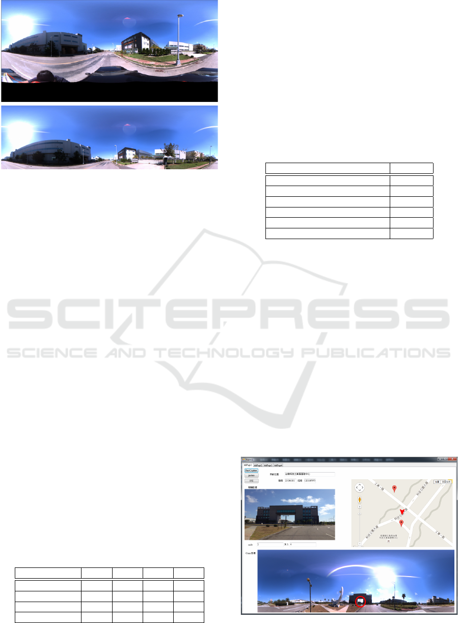
Figure 6: An example of the panoramic image in the
database. Top: the original image. Bottom: the cropped
image and used for landmark identification.
from a GPS receiver and the built-in GPS module of
the mobile phone, respectively. The Ladybug2 omni-
directional imaging system consists of 6 wide angle
cameras. Six individual images captured by Lady-
bug2 are stitched to form a single panoramic image
with the resolution of 2048 × 1024. Since the lower
part of street scene panoramic images is less impor-
tant for landmark detection, the images are further
cropped to the resolution of 2048 × 598 with the up-
per part remained (see Figure 6). The input image
captured by the mobile phone has the resolution of
3624 × 2448. To reduce the computation time, the
images are resampled to the resolution of 1088 × 816
for processing.
Four image databases used in the experiments are
constructed with different geographic regions. The
detail information is shown in the Table 1 with the to-
tal distance, the numbers of images, nodes and land-
marks. The navigation system graphical user inter-
face is shown in Figure 7. Given an input perspec-
tive image acquired by a mobile camera, it will return
the most similar panoramic image in the database and
draw a red circle as the camera heading derived from
the image. The circle location is P
c
as used in Eq. (1).
In the navigation system, the name of the landmark
is also provided according to the marker identified on
Google Map.
Table 1: The numbers of node, image and landmark ob-
tained from the datasets.
Set 1 Set 2 Set 3 Set 4
Distance (m) 673 375 1060 286
# of Node 27 14 41 12
# of Image 29 19 51 15
# of Landmark 4 5 9 3
3.1 Runtime Discussion
We test our navigation assistance system on a Win-
dows 7, 32bit PC with 4GB RAM and an Intel Core
i5 CPU. The run time of the proposed technique is
tabulated in Table 2 with processing stages. The total
execution time for all processes is 8 seconds per im-
age. Due to the image retrieval stage using 10 high
resolution panoramic images (2048 × 598), it spends
most execution time in the process and make it the
bottleneck of our system.
Table 2: The computation time for each processing stage
and the overall execution time.
Process Time (s)
Image retrieval 4.14
Extract SIFT features (query) 0.43
Extract SIFT features (dataset) 0.48
Extract line feature (query) 0.38
Extract SIFT feature (dataset) 0.47
Total execution time 8
3.2 Experimental Results
We first compare the landmark matching results. In
our system, we use line features to filter out the incor-
rect SIFT matching points. As illustrated in Figure
8, the matching results of the input and panoramic
images are shown with different methods. The top
image in Figure 8(b) shows the result only using the
SIFT features to match the input image. The small red
circles represent the matching points. It can be seen
that there are some incorrect SIFT matches which
do not correspond to the landmark’s nearby regions
in Figure 8(a). If the line features are incorporated
as shown in the bottom of Figure 8(b), most of the
wrong SIFT correspondences are eliminated success-
fully. The camera heading of Figure 8(a) is then iden-
tified correctly.
Figure 7: The graphical user interface of the visual naviga-
tion assistance system.
Visual Navigation with Street View Image Matching
589
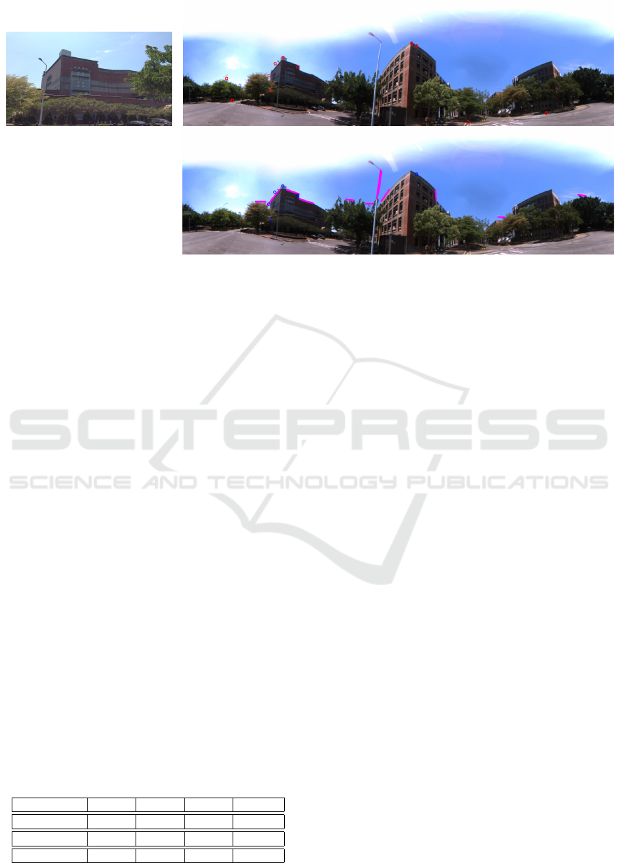
(a)
(b)
Figure 8: The results of two landmark matching approaches. The right top result only adopt SIFT to match the landmark. The
right bottom result uses the additional line feature.
To evaluate the system performance, two impor-
tant criteria for navigation assistance are adopted,
namely the correctness of landmark’s name and cam-
era’s heading direction. The camera heading is drawn
in the user interface and indicated by a red circle (say,
C
a
). Its correctness is verified by the overlap with the
landmark area (say, P
l
) in the panoramic image, i.e.,
C
a
∩ P
l
. Our technique is compared with the meth-
ods proposed by Guan et at. (Guan et al., 2014) and
Bettadapura et al. (Bettadapura et al., 2015) for per-
formance evaluation. Due to the objectives of their
works are not completely the same as ours. Only the
part of their frameworks related to image retrieval and
navigation results is used for comparison. The system
accuracy is computed using our formulation.
The image features derived from their methods are
adopted to calculate the camera heading using Eq. (1),
and the landmark’s name is obtained from the cor-
responding marker in Google Map. In (Guan et al.,
2014), the geographic information and SURF features
are adopted for image retrieval on a pre-constructed
image database. Bettadapura et al. use the geo-
graphic information to retrieve the image. The max-
imally stable extremal region (MSER) is extracted to
detect candidate points, and SIFT is used to describe
the feature points. Table 3 shows the accuracy of our
approach and these two methods performed on each
datasets.
Table 3: The performance comparison with other methods.
Set 1 Set 2 Set 3 Set 4
Our method 79.3% 78.9% 96% 80.0 %
Guan 58.6% 63.2% 76.4% 60.0%
Bettadapura 24.5% 24.1% 47.0% 33.3%
The average accuracy of our results on the datasets
is 83.6%, which is better than those obtained from the
other two methods. Some of our false navigation re-
sults are the incorrect camera headings. It is due to
the encoding error on x-coordinates in the panoramic
images. In (Guan et al., 2014) and (Bettadapura et al.,
2015), they both use the gyroscopic compass to im-
prove the performance of their systems. However, our
technique aims to use only the images and geographic
information to construct the visual navigation assis-
tance. Although the gyroscopic compass can provide
more correct camera headings in the previous works,
our system has better matching results in small ob-
jects like monuments or road signs.
4 CONCLUSIONS
In the paper, we propose a visual navigation assis-
tance system using the geographic information and
image matching. Our technique has been tested on
the real scene images and provides 83.55% accuracy
in four image datasets. In addition to the results
are better than the previous approaches, the proposed
method is also capable of landmark recognition with-
out training. The future work will focus on the inte-
gration with Google Map Street View. With the ad-
vances of wireless communication, the Google street
view image database can be accessed in real-time.
The wearable devices will also be tested to emphasize
the portability of the presented technique.
VISAPP 2016 - International Conference on Computer Vision Theory and Applications
590

ACKNOWLEDGMENTS
The support of this work in part by the National Sci-
ence Council of Taiwan under Grant NSC-102-2221-
E-194-019 is gratefully acknowledged.
REFERENCES
Altwaijry, H., Moghimi, M., and Belongie, S. (2014). Rec-
ognizing locations with google glass: A case study. In
Applications of Computer Vision (WACV), 2014 IEEE
Winter Conference on, pages 167–174.
Bay, H., Ess, A., Tuytelaars, T., and Van Gool, L. (2008).
Speeded-up robust features (surf). Comput. Vis. Image
Underst., 110(3):346–359.
Bettadapura, V., Essa, I. A., and Pantofaru, C. (2015). Ego-
centric field-of-view localization using first-person
point-of-view devices. In 2015 IEEE Winter Con-
ference on Applications of Computer Vision, WACV
2014, Waikoloa, HI, USA, January 5-9, 2015, pages
626–633. IEEE Computer Society.
Canny, J. (1986). A computational approach to edge de-
tection. IEEE Trans. Pattern Analysis and Machine
Intelligence, 8(6):679–698.
Chen, D. M., Baatz, G., Koser, K., Tsai, S. S., Vedan-
tham, R., Pylvanainen, T., Roimela, K., Chen, X.,
Bach, J., Pollefeys, M., Girod, B., and Grzeszczuk,
R. (2011). City-scale landmark identification on mo-
bile devices. In Proceedings of the 2011 IEEE Con-
ference on Computer Vision and Pattern Recognition,
CVPR ’11, pages 737–744, Washington, DC, USA.
IEEE Computer Society.
Guan, T., Fan, Y., Duan, L., and Yu, J. (2014). On-device
mobile visual location recognition by using panoramic
images and compressed sensing based visual descrip-
tors.
Hough, P. V. (1962). Method and means for recognizing
complex patterns. US Patent 3,069,654.
Hu, R. and Collomosse, J. (2013). A performance eval-
uation of gradient field hog descriptor for sketch
based image retrieval. Comput. Vis. Image Underst.,
117(7):790–806.
Huang, W.-T., Tsai, C.-L., and Lin, H.-Y. (2012). Mobile
robot localization using ceiling landmarks and images
captured from an rgb-d camera. In Advanced Intelli-
gent Mechatronics (AIM), 2012 IEEE/ASME Interna-
tional Conference on, pages 855–860.
Hughes, J. F., van Dam, A., McGuire, M., Sklar, D. F.,
Foley, J. D., Feiner, S. K., and Akeley, K. (2013).
Computer graphics: principles and practice (3rd ed.).
Addison-Wesley Professional, Boston, MA, USA.
Juan, L. and Gwun, O. (2009). A comparison of sift, pca-sift
and surf. International Journal of Image Processing
(IJIP), 3(4):143–152.
Laungrungthip, N., McKinnon, A., Churcher, C., and
Unsworth, K. (2008). Edge-based detection of sky
regions in images for solar exposure prediction. In
Image and Vision Computing New Zealand, 2008.
IVCNZ 2008. 23rd International Conference, pages 1–
6.
Lin, H., Lin, Y., and Yao, J. (2013). Scene change de-
tection and topological map construction using om-
nidirectional image sequences. In Proceedings of the
13. IAPR International Conference on Machine Vision
Applications, MVA 2013, Kyoto, Japan, May 20-23,
2013, pages 57–60.
Liu, H., Mei, T., Luo, J., Li, H., and Li, S. (2012). Finding
perfect rendezvous on the go: Accurate mobile visual
localization and its applications to routing. In Pro-
ceedings of the 20th ACM International Conference
on Multimedia, MM ’12, pages 9–18, New York, NY,
USA. ACM.
Lowe, D. G. (2004). Distinctive image features from scale-
invariant keypoints. Int. J. Comput. Vision, 60(2):91–
110.
Mulloni, A., Wagner, D., Barakonyi, I., and Schmalstieg, D.
(2009). Indoor positioning and navigation with cam-
era phones. Pervasive Computing, IEEE, 8(2):22–31.
Philbin, J., Chum, O., Isard, M., Sivic, J., and Zisserman, A.
(2007). Object retrieval with large vocabularies and
fast spatial matching. In IEEE Conference on Com-
puter Vision and Pattern Recognition, pages 1–8.
Resch, B., Lang, J., and Lensch, H. (2014). Local image
feature matching improvements for omnidirectional
camera systems. In Pattern Recognition (ICPR), 2014
22nd International Conference on, pages 918–923.
Saab, S. and Nakad, Z. (2011). A standalone rfid indoor po-
sitioning system using passive tags. Industrial Elec-
tronics, IEEE Transactions on, 58(5):1961–1970.
Siddiqui, J. and Khatibi, S. (2014). Semantic urban maps. In
Pattern Recognition (ICPR), 2014 22nd International
Conference on, pages 4050–4055.
Turcot, P. and Lowe, D. (2009). Better matching with
fewer features: The selection of useful features in
large database recognition problems. In Computer Vi-
sion Workshops (ICCV Workshops), 2009 IEEE 12th
International Conference on, pages 2109–2116.
Uchiyama, H., Saito, H., Servieres, M., and Moreau, G.
(2009). Image based view localization system retriev-
ing from a panorama database by SURF. In Proceed-
ings of the IAPR Conference on Machine Vision Ap-
plications (IAPR MVA 2009), Keio University, Yoko-
hama, Japan, May 20-22, 2009, pages 118–121.
Wang, S., Wang, Y., and Zhu, S.-C. (2015). Learning hier-
archical space tiling for scene modeling, parsing and
attribute tagging. Pattern Analysis and Machine Intel-
ligence, IEEE Transactions on, PP(99):1–1.
Yao, C.-W., Cheng, K.-S., and Lin, H.-Y. (2014). A vi-
sion assisted vehicle navigation technique based on
topological map construction and scene recognition.
In Advanced Video and Signal Based Surveillance
(AVSS), 2014 11th IEEE International Conference on,
pages 399–404.
Zamir, A. R. and Shah, M. (2010). Accurate image local-
ization based on google maps street view. In Proceed-
ings of the 11th European Conference on Computer
Vision: Part IV, ECCV’10, pages 255–268, Berlin,
Heidelberg. Springer-Verlag.
Visual Navigation with Street View Image Matching
591
