
Real-time Image Vectorization on GPU
Xiaoliang Xiong, Jie Feng and Bingfeng Zhou
Institute of Computer Science and Technology, Peking University, Beijing, China
Keywords:
Vectorization, Real-time Rendering, GPU Acceleration.
Abstract:
In this paper, we present a novel algorithm to convert a raster image into its vector form. Different from the
state-of-art methods, we explore the potential parallelism that exists in the problem and propose an algorithm
suitable to be accelerated by the graphics hardware. In our algorithm, the vectorization task is decomposed
into four steps: detecting the boundary pixels, pre-computing the connectivity relationship of detected pixels,
organizing detected pixels into boundary loops and vectorizing each loop into line segments. The boundary
detection and connectivity pre-computing are parallelized owing to the independence between scanlines. After
a sequential boundary pixels organizing, all loops are vectorized concurrently. With a GPU implementation,
the vectorization can be accomplished in real-time. Then, the image can be represented by the vectorized
contour. This real-time vectorization algorithm can be used on images with multiple silhouettes and multi-
view videos. We demonstrate the efficiency of our algorithm with several applications including cartoon and
document vectorization.
1 INTRODUCTION
Vector image is a compact form to represent image
with a set of geometry primitives (like points, curves
or polygons). It is independent with displaying
resolution so that it can be rendered at any scale
without aliasing. A raster image, in contrast, uses
a large pixel matrix to store the image information,
which requires much more space and conveys less
semantics. It can be directly mapped onto display
device and rendered with high efficiency, but suffers
seriously from aliasing or loss of details when the
image is scaled. The advantages of vector image over
raster image, make it widely used in situations such
as computer-aided design, on the Internet and plenty
of practical applications.
Shape-from-Silhouette (SFS) is a specific appli-
cation which adopts vector form as silhouette rep-
resentation. It retrieves the 3D shape of the tar-
get object from multiple silhouette images taking at
different viewpoints. In SFS, silhouette boundaries
are approximated by line segments to simplify the
computation and achieve the real-time rendering per-
formance. Thus, an efficient algorithm to convert the
silhouettes from pixels to vectors is essential. This is
This work is partially supported by NSFC grants
#61170206, #61370112, and Specialized Research
Fund for the Doctoral Program of Higher Education
#20110001110077.
the motivation of our work. Also, it is necessary to do
the raster-to-vector conversion with high efficiency in
applications like high-speed document scanning and
cartoon animation.
Existing vectorization methods mainly focus on
the accuracy during the conversion and ideally expect
to approximate both the sharp and smooth features in
the raster image with less geometry primitives. Tri-
angular mesh (Zhao et al., 2013), gradient mesh (Sun
et al., 2007) and diffusion curves (Orzan et al., 2013)
are three commonly used geometry representatives.
There are some researches adopt GPU to improve
the rendering speed of constructed vector image (Xia
et al., 2009), but the efficiency of the vector image
construction is not high enough.
In contrast, we focus primarily on the silhouettes
in the raster image and explore the potential paral-
lelism in the problem to vectorize their contours as
fast as possible. Both accuracy and efficiency are
concerned to satisfy practical applications. Inspired
by the scanline algorithm in polygon filling, we first
detect the boundary pixels line by line in parallel,
resulting in a set of unorganised pixels on each line.
So secondly, the relationships of these pixels are
computed. We note that only adjacent lines are
directly related and each two lines can be processed
simultaneously. Thirdly, all the boundary pixels are
organized into loops based on pre-computed relation-
ship. Fourthly, these loops which consist of boundary
Xiong, X., Feng, J. and Zhou, B.
Real-time Image Vectorization on GPU.
DOI: 10.5220/0005668901410148
In Proceedings of the 11th Joint Conference on Computer Vision, Imaging and Computer Graphics Theory and Applications (VISIGRAPP 2016) - Volume 1: GRAPP, pages 143-150
ISBN: 978-989-758-175-5
Copyright
c
2016 by SCITEPRESS – Science and Technology Publications, Lda. All rights reserved
143

pixels can be vectorized into line segments concur-
rently. Hence, the problem is naturally decomposed
into four steps and three steps can be parallelized.
With this decomposition, our algorithm becomes not
so sensitive to the image resolution.
Our key contribution is a novel algorithm that
vectorizes the silhouettes in a raster image with high
efficiency. We make a decomposition on the problem
and take advantage of the potential parallelism to get
an acceleration. We also apply the algorithm into
several practical situations.
2 RELATED WORK
Comparing to raster images, vector images has the ad-
vantages of more compact in presentation, requiring
less space to store, convenient to transmit and edit,
artifact-free in display etc. Image vectorization tech-
niques aim at doing the raster-to-vector conversion
accurately and efficiently. It includes crude vector-
ization on binary images and advanced vectorization
on color images.
2.1 Image Vectorization
Crude Vectorization. Crude vectorization
concerns grouping the pixels in the raster image
into raw line fragments and representing the original
image with primary geometry like skeleton and
contour polygon. It is a fundamental process in the
interpretation of image elements (like curves, lines)
and can be used as preprocessing of applications like
cartoon animation, topographic map reconstruction,
SFS, etc.
Crude vectorization is often divided into two
classes: Thinning based methods (Smith, 1987)
and Non-thinning based methods (Jimenez and
Navalon, 1982). The former first thin the rastered
object into a one-pixel-wide skeleton with iterative
erosion, then these pixels are tracked into chain and
approximated with line segments. The latter first
extract the contour of the image, compute the medial
axis between the contour pixels and then do the line
segment approximation. Thinning based methods
lose line width information during erosion and is time
consuming. These disadvantages are compensated by
non-thinning based methods that may have gaps at
junctions. And both of these methods are sequential
and need a long process time. (Dori and Liu, 1999)
present a new medial axis pixel tracking strategy,
which can preserve the width information and avoid
distortion at junctions.
Advanced Vectorization. Advanced vectorization
approaches concentrate on accurate approximation
for all features in the raster image and take accuracy
as their first consideration. Triangle mesh based
methods (Zhao et al., 2013) first sample important
points in the image, then decompose this image into
a set of triangles and store the corresponding pixel
color on the triangle vertices. Inside each triangle,
the color of each pixel can be recalculated through
interpolation. (Xia et al., 2009) converts the image
plane into triangular patches with curved boundaries
instead of simple triangles and make the color dis-
tribution inside each patch more smooth. Diffusion
curve based methods (Orzan et al., 2013) first detect
the edges in the original image, based on which
it is converted into diffusion curve representation.
Then a Poisson Equation is solved to calculate the
final image. After vectorization by these methods,
image can be effectively compressed, features are
maintained or enhanced in different extent.
2.2 Image Vectorization in Applications
Cartoon Animation. In automatic cartoon anima-
tion, the artists only need to draw the key frames
and in-betweens are generated by shape matching and
interpolation. However, these techniques cannot be
directly used in raster images, but are more suitable
for vector-based graphics. Thus, a vectorization pro-
cess is required to convert a raster key frame into its
vector form. (Zou and Yan, 2001) subdivide the car-
toon character into non-overlapping triangles based
on which skeleton is extracted. Then artifacts are
removed at the junction points and intersection areas
by optimizing the triangles.There are also researches
(Zhang et al., 2009) on converting raster cartoon film
into its vector form because the vector version is
more easy to store, transmit, edit, display and so on.
They take temporal coherence into consideration to
alleviate flicker between cartoon frames.
Shape-from-Silhouette. Shape-from-Silhouette
(SFS) is a method of estimating 3D shape of an
object from its silhouette images. One famous
SFS technique is the visual hull (Laurentini, 1994;
Matusik et al., 2000). VH is defined as the maximal
shape that reproduces the silhouettes of a 3D
object from any viewpoint. It can be computed by
intersecting the visual cones created by the viewing
rays emanating from the camera center and passing
through the silhouette contours, which is originally
a chain of pixels. Most existing works adopt line
segments as an approximation of the silhouette
contour to reduce large amount of redundant
GRAPP 2016 - International Conference on Computer Graphics Theory and Applications
144
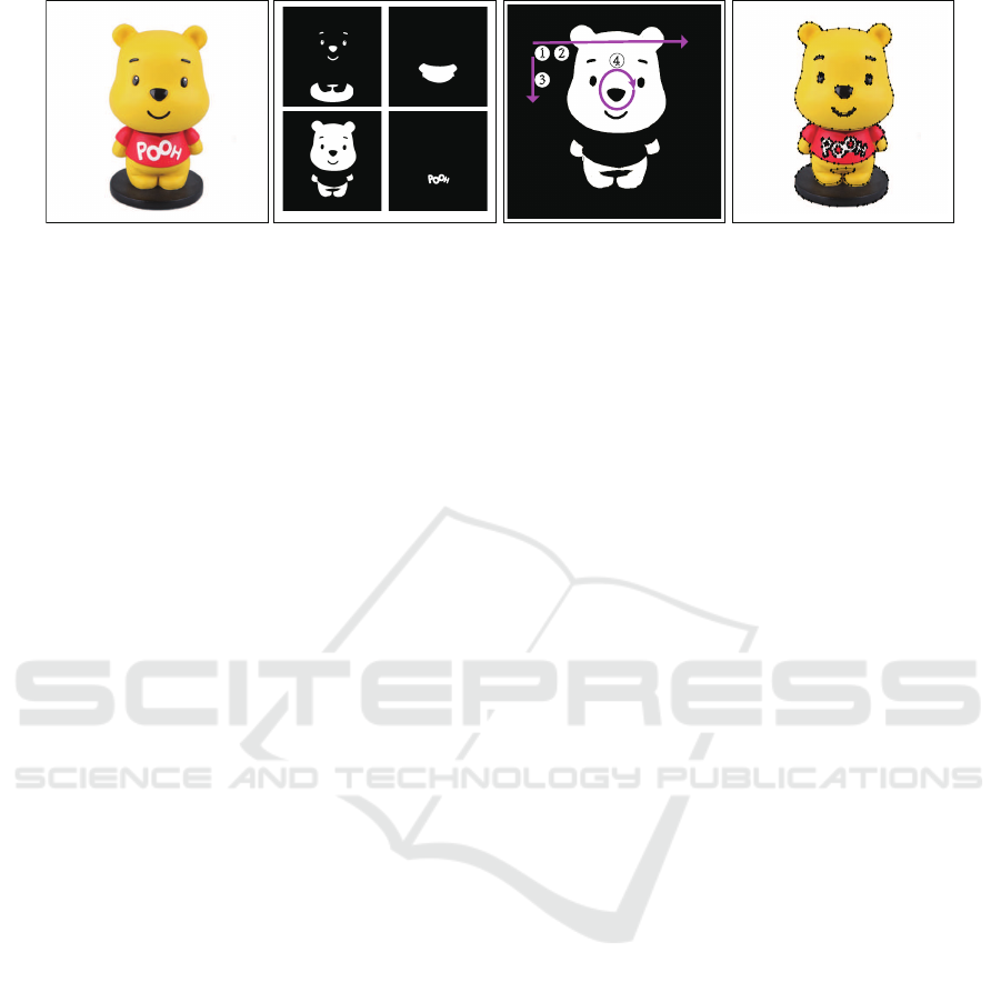
Figure 1: Vectorizing a cartoon color image with our method. (a)The input raster image. (b)The binary silhouettes. (c)The
main procedure of our algorithm:
1
parallel boundary detection and
2
precontouring,
3
sequential contouring and
4
parallel
contour vectorization. (d)The vectorization result. The contours are represented by line segments. The whole computation is
completed in 9ms, which provides possibility for real-time applications.
computation. The conversion from silhouette contour
to line segments is originally a vectorization problem
and efficient algorithm is needed to decrease time
consumption in VH pre-computing.
(Matusik et al., 2000) and (Li et al., 2004)
adopt complex hardware like multi-processors and
distributed system to do this step to guarantee the VH
computation in real-time. There are many GPU-based
methods (Ladikos et al., 2008; Waizenegger et al.,
2009; Yous et al., 2007) to accelerate the visual hull
computation, for the VH algorithm is highly parallel.
Thus, it is natural to think if the preprocessing can be
parallelized, too. This is the motivation of our work
and draws our attention mainly on the parallelization
of contour vectorization.
Document Image Processing. Document process-
ing is a complex procedure which evolves converting
the text on paper or electronic documents into features
the computer can recognize. (Chang et al., 1999)
present a thinning algorithm based on line sweep
operation, resulting in a representation with skeletons
and intersection sets, that provides extra features for
subsequent character recognition. It is efficient in
computation comparing to pixel-based thinning algo-
rithm (Smith, 1987) which outputs skeletons only.
GPU-acceleration in Image Vectorization. Exist-
ing GPU related work is on the vectorized image
rendering. (Nehab and Hoppe, 2008) introduce a
novel representation for random-access rendering of
antialiased vector graphics. It has the ability to
map vector graphics onto arbitrary surfaces, or under
arbitrary deformations. (Xia et al., 2009) develop a
real-time GPU-accelerated parallel algorithm based
on recursive patch subdivision for rasterizing their
vectorized results. (Orzan et al., 2013) also propose
a GPU implementation for rendering their vectorized
images described by diffusion curves.
3 Our Algorithm
Our goal is to convert the silhouettes in an input
image from raster to vector form with high efficiency
and accuracy. The input image is preprocessed and
converted into silhouette images by thresholding or
background subtraction in advance. Intuitively, the
boundary pixels are detected by scanning each line
in these images. Since all scanlines are independent,
the detection can be done concurrently. The resulting
pixels on each line are then organized into loops
based on their connectivity relationship with previous
line, which can be precomputed in parallel. Finally,
all organized loops are vectorized into line segments
independently. Fig.1 shows the process of vectorizing
a cartoon color image with our method. In the follow-
ing, we describe each step in detail. To clarify the
description, we refer boundary as unordered pixels,
loop as an ordered pixel list and contour as all loops
of a silhouette.
3.1 Boundary Pixel Detecting
To rapidly extract the boundary pixels, we scan all
lines in the silhouette images in parallel. A scanline
ˆs
i
is a one-pixel-wide horizontal line that crosses the
silhouette image from left to right. It is used to find
the pairwise boundary pixels (I
k
,O
k
) of a foreground
area. The collection of all scanlines are denoted as S,
S = { ˆs
i
|i = 1, . . . , h},
where h is the height of silhouette image. During
scanning, when the scanline enters the foreground
from background, the corresponding boundary pixel
is recorded as I
k
and when it leaves foreground into
background, the boundary pixel is recorded as O
k
.
The point pair (I
k
, O
k
) is called an interval R
(i)
k
on
ˆs
i
, and the pixels between I
k
and O
k
belong to the
foreground. All such pixel pairs on ˆs
i
consist its
Real-time Image Vectorization on GPU
145
interval collection s
i
,
s
i
= {R
(i)
k
|R
(i)
k
= (I
k
, O
k
), I
k
< O
k
, 1 ≤ k ≤ N
i
},
where line ˆs
i
has N
i
intervals. Fig.2 shows an example
of two scanlines ˆs
i
0
and ˆs
i
1
. In each line, pixels are
illustrated in different colors, where black indicates
background, cyan for boundary pixels and gray for
foreground. In the example, line ˆs
i
0
has 3 intervals
and ˆs
i
1
has 4 intervals respectively.
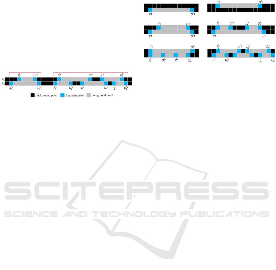
Figure 2: Example of scanlines, intervals and segments. In
this example, intervals on line ˆs
i
0
and ˆs
i
1
are divided into 2
segments, each marked with a red box.
As the independence of boundary pixel detection
on each line ˆs
i
, the scanning task of all lines S in the
silhouette images can be allocated to multiple parallel
threads, each for one scanline. This parallelization
has an advantage: when the height of the image or
the image number increases, we only need to add
more threads and the running time is not affected too
much. And it provides possibility for multiple images
vectorization. The parallel scanning results in a group
of foreground pixel intervals s
i
on each line and the
connectivity relationship between the lines should be
computed in next step.
3.2 Pre-contouring
The detected boundary pixels are represented as fore-
ground intervals s
i
on each line ˆs
i
. They should
be organized into loops that enclose the object in
the silhouette images. The target contour loops are
denoted as B:
B = {L
j
| j = 1, . . . , l},
where l is the loop number and each loop L
j
is a
ordered list of boundary pixels:
L
j
= {p
m
|m = 1, . . . , M},
That is, the loop L
j
starts from p
1
, goes along
the silhouette and ends at p
M
. If contour loops B
are tracked directly on S, it is an up-down strategy
that each loop stretches to pixels on next line if
corresponding intervals are connected with current
loop. The connectivity relationship between intervals
on adjacent lines is needed during contour tracking
and should be computed first.
For arbitrary two adjacent lines ˆs
i
0
and ˆs
i
1
, their
connectivity depends on the overlapping of their fore-
ground intervals. If intervals R
(i
0
)
j
in s
i
0
and R
(i
1
)
k
in
(a) 1:0 (b) 0:1
(c) 1:1 (d) 1:n
(e) n:1 (f) n:n
Figure 3: Six cases of the connectivity relationship between
intervals on two adjacent lines.
s
i
1
overlap, they consist a segment. In Fig.2, R
(i
0
)
1
and R
(i
1
)
1
overlap, so they consist a segment, based on
which we can infer these four boundary pixels are in
the same loop. In this example, the rest of intervals on
line ˆs
i
0
and ˆs
i
1
are divided into another segment and it
has 3 intervals on i
1
and 2 on i
0
(3:2).
Theoretically, in the same segment the ratio of
interval numbers on two adjacent lines can be clas-
sified into six cases:(1)1:0 (2)0:1 (3)1:1 (4)1:n (5)n:1
(6)n:n (Fig.3). Case (1) and case (2) means interval
only existing in one of the lines; Case (3) means that
current loop does not change obviously from previous
line to current line; case (4) and case (5) indicate
loops merged or closed and new loops generated
respectively; case (6) is a combination of case (4) and
case (5). Each case indicates different change of loops
in these lines and the boundary pixels of the included
intervals are related.
Because this relationship computing depends only
on the adjacent lines, it can be performed in paral-
lel and separately accomplished as a pre-processing
before contour organizing. Each parallel thread is
responsible for dividing intervals on two lines into
segments. With the connectivity relationship, we can
organize each loop in order more efficiently.
3.3 Contouring
Up to now, the boundary pixels are detected and
pre-contoured in parallel, resulting in the foreground
intervals and their connectivity relationship between
adjacent lines. With these information, we can orga-
nize the boundary pixels into loops more easily, which
is accomplished in each segment, according to the
interval numbers in the two lines. During organizing,
new loops may be generated, existing loops may be
extended, merged, closed or branched from top to
bottom in the image. The connectivity relationship
between the two adjacent lines determines how the
loop develops from the previous line to the current
line, which can be directly represented by the interval
GRAPP 2016 - International Conference on Computer Graphics Theory and Applications
146

numbers on each line(|{R
(i
1
)
k
}| : |{R
(i
0
)
j
}|)).
As described in Pre-contouring, in each individual
segment, the connectivity relationship of adjacent
lines can be classified into 6 cases, and each case
means loop changes differently in these lines. Next,
we will consider each case separately and show how
the loops develop from previous line to current line as
illustrated in fig.3.
• Loop Initialization (1:0)
During Contouring, a new loop is generated when
new interval appears on current line, which does not
overlap with any intervals on previous line. This loop
records the boundary pixels of a presently separate
region in the input image and will be complemented
by the following pixels. As shown in fig.3(a), a loop
starting from I
(i
1
)
and ends at O
(i
1
)
is generated.
• Loop Termination (0:1)
A loop is terminated when there is only an interval on
the previous line in one segment. It indicates all pixels
on a separate region are organised into a closed loop,
which is called a contour in our algorithm. In fig.3(b),
the corresponding loop of I
(i
0
)
and I
(i
0
)
is terminated.
• Loop Extension (1:1)
In one segment, if there is an interval on each line, it
indicates the shape changes slightly in these two lines
and the loop from the previous line can simply extend
to the boundary pixels on current line. As shown in
Fig.3(c), for each interval in s
i
0
and s
i
1
:
s
i
0
= {R
(i
0
)
= (I
(i
0
)
, O
(i
0
)
)},
s
i
1
= {R
(i
1
)
= (I
(i
1
)
, O
(i
1
)
)},
we add boundary points I
(i
1
)
and O
(i
1
)
into the corre-
sponding loops of I
(i
0
)
and O
(i
0
)
, respectively.
• Loop Merging or Closing (1:n)
In this case, n intervals on the previous line change
into one on current line. It means the loop number
decreases and there are loops merged or closed. As
shown in Fig.3(d), there are n intervals in s
i
0
and 1
interval in s
i
1
:
s
i
0
= {R
(i
0
)
j
|R
(i
0
)
j
= (I
(i
0
)
j
, O
(i
0
)
j
), 1 ≤ j ≤ n},
s
i
1
= {R
(i
1
)
= (I
(i
1
)
, O
(i
1
)
)}.
Hence, we add I
(i
1
)
, O
(i
1
)
into the corresponding loops
of I
(i
0
)
1
, O
(i
0
)
n
, respectively. For the rest of points in s
i
0
,
new pairs are formed as (O
(i
0
)
w
, I
(i
0
)
w+1
), w = 0, . . . , n−1.
If the points of one pair belongs to the same loop, this
loop will be closed, or else the different loops will be
merged.
• Loop Branching (n:1)
On the contrary to the previous case, if 1 interval on
previous line branches into n intervals on current line,
new loops are generated to record the boundary pixels
on the following line. In Fig.3(e), there are n intervals
in s
i
1
and 1 interval in s
i
0
:
s
i
1
= {R
(i
1
)
k
|R
(i
1
)
k
= (I
(i
1
)
k
, O
(i
1
)
k
), 1 ≤ k ≤ n},
s
i
0
= {R
(i
0
)
= (I
(i
0
)
, O
(i
0
)
)}.
We add I
(i
1
)
1
, O
(i
1
)
n
into the corresponding loop of
I
(i
0
)
, O
(i
0
)
, respectively. For the left points in s
i
1
,
new pairs are formed as (O
(i
1
)
w
, I
(i
1
)
w+1
), w = 0, . . . , n−1.
Each pair is used for generating a new loop.
• Loop Merging(Closing) and Branching (n:n)
If there are more than 1 intervals on both lines in a
segment, we can treat it as a combination of the case
of loop merging(closing) and branching. In Fig.3(f),
there are n intervals in s
i
0
and m intervals in s
i
1
:
s
i
0
= {R
(i
0
)
j
|R
(i
0
)
j
= (I
(i
0
)
j
, O
(i
0
)
j
), 1 ≤ j ≤ n},
s
i
1
= {R
(i
1
)
k
|R
(i
1
)
k
= (I
(i
1
)
k
, O
(i
1
)
k
), 1 ≤ k ≤ m}.
We add I
(i
1
)
1
, O
(i
1
)
m
into the corresponding loop of
I
(i
0
)
1
, O
(i
0
)
n
, respectively. Loops are merged or closed
for the rest of points in s
i
0
and generated for the rest
of points in s
i
1
.
These six cases provide the rule for how to deal
with boundary pixels on current line according to the
connectivity relationship with previous line during
loop organizing. This step must be in sequential
manner because the boundary pixels on current line
must be connected to the loops produced by previous
boundary pixels. Furthermore, the computation need
large memory to store the edge pixels and requires
frequent memory access, which is the weakness of
GPU. And this is the only step that has to be per-
formed on CPUs. When all lines of silhouette images
are processed, target loops B is generated.
3.4 Contour Vectorization
Using the method given above, the contour of the
foreground can be described with a group of pixel
loops B. Subsequently, we need to simplify each loop
and approximate them with a set of line segments.
Our approximation method is similar to the Active
Contour Modeling (Kass et al., 1988). Each loop L
j
=
{p
1
p
2
··· p
i
··· p
M−1
p
M
} is processed with a divide-
and-conquer strategy. Let d be the maximum distance
between the point p
i
and line p
1
p
M
:
d = max{dist(p
i
,
−−−→
p
1
p
M
)}.
Real-time Image Vectorization on GPU
147
if d is smaller than t (a constant threshold, we set
t=1 in our experiment), p
1
p
M
is an approximate line
segment and the discretization terminates. If not, loop
L
j
is divided into two sub-loops L
j
0
and L
j
1
:
L
j
0
= {p
1
p
2
p
i
p
M+1
2
},
L
j
1
= {p
M+1
2
··· p
j
··· p
M−1
p
M
}.
Then each sub-loop is tested iteratively until L
j
0
or L
j
1
satisfies the terminal condition or is small enough.
The vectorization of each loop is independent and
we can process it with a GPU thread. When the
loop number is small, the parallelism is limited and it
has little improvement in performance comparing to
processing each loop sequentially. The parallelizing
of this step become more and more important as the
increasing of the loop number.
When the four steps are completed, our algorithm
can output a vector image with contour represented
by line segments.
4 EXPERIMENT AND RESULT
We implement our algorithm using CUDA on a com-
mon PC with Quad CPU 2.5GHz, 2.75GB RAM, and
a GeForce GTX260+ graphic card. The vectorization
task is decomposed into four steps, in which Bound-
ary Detection and Pre-contouring are performed on
GPU with multiple threads, each processing for dif-
ferent lines. Pre-contouring results are copied back to
CPU for sequential computation of Contouring, and
the organized contour loops are copied into the GPU
for the final Vectorization.
Fig.4 shows the vectorization results of some sim-
ple characters and figures. The former is inevitably
used in document processing and the latter is used in
silhouette-based applications, e.g. SFS. The running
time and the number of primitives used for vector
representation are listed in Table 1.
Comparison. We compare our algorithm with a
Floodfill-based method on time efficiency. The dif-
ference between them is the strategy of boundary
pixel detection and ordering, and we use the same
way to vectorize the contour loops. Floodfill based
method iteratively searches the boundary pixels of
the silhouette in neighborhood until all pixels are
processed. Hence the running time increases expo-
nentially with the image resolution and it depends
heavily on the complexity of the scene. In contrast,
our method detects and pre-contours the boundary
pixels in parallel. The grouped pixels organizing
depends a little on the image complexity, but not so
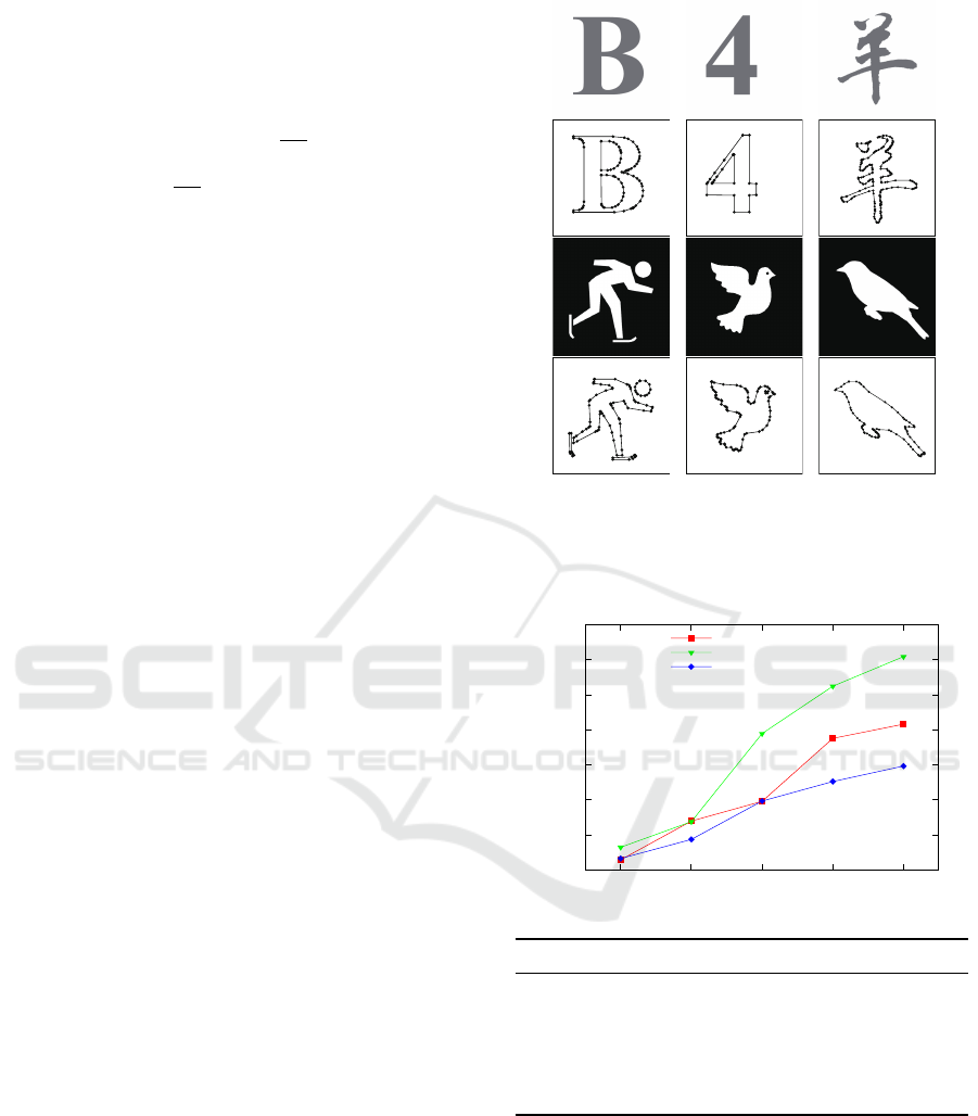
Figure 4: Vectorization results. The first and third rows
are input raster images(First row: CharB, Digit4, Chinese
character. Third row: Skater, Pigeon, Bird.), and the second
and fourth rows are corresponding vectorization results with
contour represented by line segments.
0
10
20
30
40
50
60
70
200x200 400x400 600x600 800x800 1000x1000
speedup ratio
image resolution
Bird
Pegion
Skateman
200
2
400
2
600
2
800
2
1000
2
Pegion FBM 29.91 105.39 306.41 510.11 799.78
Ours 4.58 7.62 7.81 9.73 13.14
Skater FBM 18.79 67.55 168.0 293.45 420.8
Ours 5.62 7.73 8.52 11.61 14.17
Bird FBM 14.51 90.53 158.26 419.94 583.28
Ours 4.87 6.46 8.06 11.18 14.01
Figure 5: Comparison between Floodfilled based method
(FBM) and our method. The figure above shows the
speedup ratio between two methods on different image
resolution and the corresponding running time(ms) of each
method is listed below.
sensitive thanks to the pre-contouring. Fig.5 shows
the speed up ratio between Foodfill Based Method
and our method on the three images with different
resolution and gives the corresponding running time
GRAPP 2016 - International Conference on Computer Graphics Theory and Applications
148
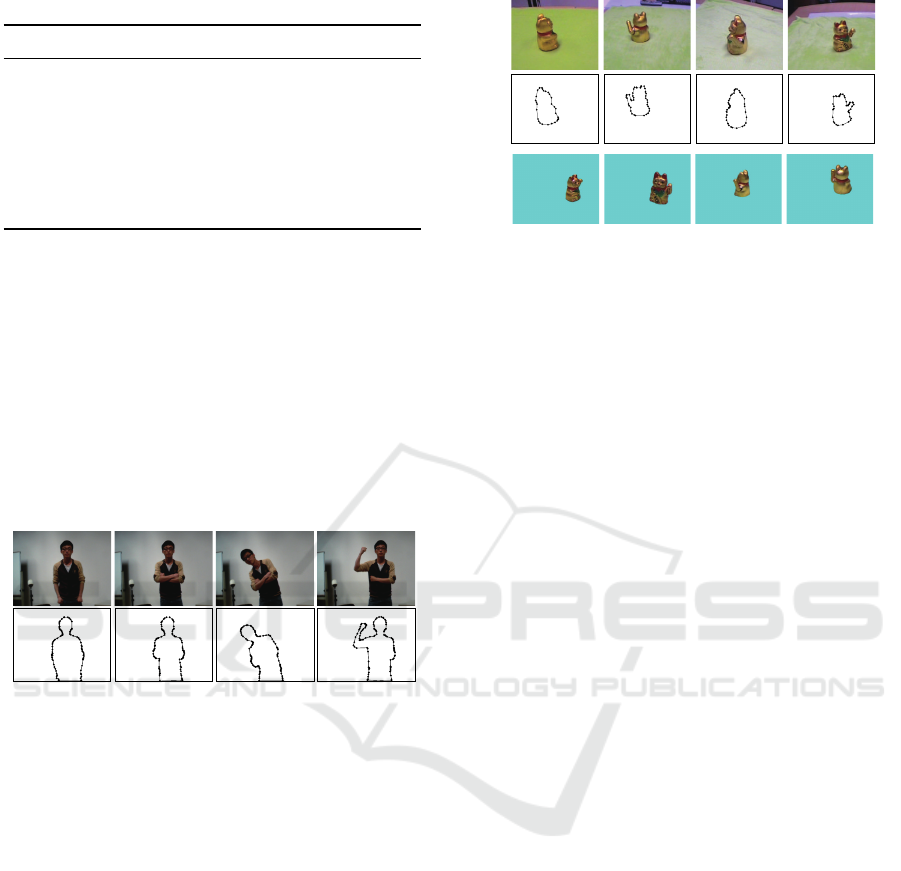
Table 1: Statistics of vectorization results and running time.
image resolution points edges loops time(ms)
CharB 600x600 626 84 3 6.51
Digit4 600x600 414 24 2 5.93
Pegion 400x400 439 86 2 5.89
Skater 400x400 596 104 4 6.56
Bird 600x480 833 83 1 8.92
Yang 600x480 982 203 2 9.75
Winnie 500x500 2761 432 26 8.54
of each method. We can see that our method is not
so sensitive to image resolution due to its parallelism
and has a significant speed up especially under high
image resolution.
Video Vectorization. Taking advantage of the fast
speed, we apply our algorithm in video vectorization.
Each frame is vectorized individually and we can
achieve an average frame rate of 48 fps, which we
believe will be even faster if the temporal coherence
is considered. Fig.6 demonstrates the result.
Figure 6: Video vectorization. First row: Four frames in the
video. Second row: the corresponding vectorized results.
To further demonstrate the efficiency of our
method, we perform the contour vectorization among
8-channel multi-view video streams simultaneously
(which is a requirement of reconstructing dynamic
visual hull) with image resolution of 600x480. Owing
to the parallelization of our algorithm, the boundary
pixels can be detected and pre-contoured in parallel
among all video image lines at one time point. Then
the pixels contouring can be parallelized between
each video. Finally, each loop in the contour can be
discretized into line segments in parallel. With the
vectorization result, we can reconstruct and render
dynamic VHs over 20 fps (Fig.7).
Cartoon Image Vectorization. Fig.1 shows the
vectorization of a cartoon image Winnie. We first
binarize the input image according to the different
colors and obtain a series of silhouettes. Then these
silhouette images are vectorized simultaneously and
result in a vector representation of the color image.
Total computation can be accomplished in 9 ms.
Vectorized Sil Input video
Visual Hulls
Figure 7: Silhouettes vectorization in eight video streams
and Visual Hull rendering based on the silhouettes. The
first row shows 4 channel video images(eight in total),
the second row is the corresponding vectorized silhouettes.
Visual hulls are rendered from different viewpoints based
on the silhouettes(the third row).
Document Image Vectorization. Document image
vectorization is challenging for complex situations
may appear in scanned document or handwritten
pages and the number of contours may be large
enough to bring difficulties in data storing and trans-
ferring on GPUs. To demonstrate the efficiency of our
algorithm, we input a typed page at the resolution of
2500x1800, and the vectorization of the characters in
this page can be done in 40 ms (Fig.8). After vector-
ization, each character is represented with several line
segments, which can be scaled without aliasing.
5 CONCLUSION
We propose a hardware-accelerated algorithm to vec-
torize the silhouettes in the raster image with high
efficiency. The problem is decomposed into four steps
and three of them can be parallelized significantly.
We show the efficiency of our algorithm on some
challenge applications including multiple videos and
document image vectorization.
The limitation of our work lies in that the con-
touring step is still in sequential. One feasible way
to alleviate the problem is to partition the silhouette
image into several parts and the contouring among
them can be parallelized. However, a merge step
is needed if loops between two parts are connected,
which will introduce extra computation cost. And we
are exploring an ideal solution for this problem.
REFERENCES
Chang, F., Lu, Y.-C., and Pavlidis, T. (1999). Feature
analysis using line sweep thinning algorithm. IEEE
Real-time Image Vectorization on GPU
149
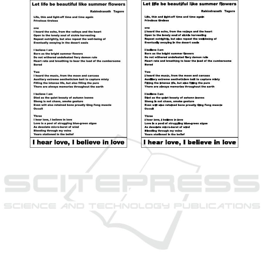
Figure 8: Vectorization of a typed document page. Left:the input document, right:the vectorized result. The input image
suffers from aliasing when the page is scaled and our result can keep the shape of each character well.
Transactions on Pattern Analysis and Machine Intel-
ligence, 21(2):145–158.
Dori, D. and Liu, W. (1999). Sparse pixel vectorization:
An algorithm and its performance evaluation. Pattern
Analysis and Machine Intelligence, IEEE Transac-
tions on, 21(3):202–215.
Jimenez, J. and Navalon, J. L. (1982). Some experiments
in image vectorization. IBM Journal of research and
Development, 26(6):724–734.
Kass, M., Witkin, A., and Terzopoulos, D. (1988). Snakes:
Active contour models. International journal of
computer vision, 1(4):321–331.
Ladikos, A., Benhimane, S., and Navab, N. (2008).
Efficient visual hull computation for real-time 3d
reconstruction using cuda. pages 1–8.
Laurentini, A. (1994). The visual hull concept for
silhouette-based image understanding. Pattern
Analysis and Machine Intelligence, 16(2):150–162.
Li, M., Magnor, M., and Seidel, H.-P. (2004). A
hybrid hardware-accelerated algorithm for high qual-
ity rendering of visual hulls. In Proceedings of
Graphics Interface 2004, pages 41–48. Canadian
Human-Computer Communications Society.
Matusik, W., Buehler, C., Raskar, R., Gortler, S. J., and
McMillan, L. (2000). Image-based visual hulls. In
SIGGRAPH 2000, pages 369–374. ACM.
Nehab, D. and Hoppe, H. (2008). Random-access rendering
of general vector graphics. In ACM Transactions on
Graphics (TOG), volume 27, page 135. ACM.
Orzan, A., Bousseau, A., Barla, P., Winnem
¨
oller, H.,
Thollot, J., and Salesin, D. (2013). Diffusion curves:
a vector representation for smooth-shaded images.
ACM Transactions on Graphics, 56(7):101–108.
Smith, R. W. (1987). Computer processing of line images:
A survey. Pattern recognition, 20(1):7–15.
Sun, J., Liang, L., Wen, F., and Shum, H.-Y. (2007). Image
vectorization using optimized gradient meshes. In
ACM Transactions on Graphics (TOG), volume 26,
page 11. ACM.
Waizenegger, W., Feldmann, I., Eisert, P., and Kauff, P.
(2009). Parallel high resolution real-time visual hull
on gpu. In Image Processing (ICIP), 2009 16th IEEE
International Conference on, pages 4301–4304.
Xia, T., Liao, B., and Yu, Y. (2009). Patch-based
image vectorization with automatic curvilinear feature
alignment. In ACM Transactions on Graphics (TOG),
volume 28, page 115. ACM.
Yous, S., Laga, H., Kidode, M., and Chihara, K. (2007).
Gpu-based shape from silhouettes. In Proceedings
of the 5th international conference on Computer
graphics and interactive techniques in Australia and
Southeast Asia, pages 71–77. ACM.
Zhang, S.-H., Chen, T., Zhang, Y.-F., Hu, S.-M., and
Martin, R. R. (2009). Vectorizing cartoon animations.
IEEE Transactions on Visualization and Computer
Graphics, 15(4):618–629.
Zhao, J., Feng, J., and Zhou, B. (2013). Image vectorization
using blue-noise sampling. In IS&T/SPIE Electronic
Imaging, pages 86640H–86640H. International Soci-
ety for Optics and Photonics.
Zou, J. J. and Yan, H. (2001). Cartoon image vectorization
based on shape subdivision. In Computer Graphics
International 2001. Proceedings, pages 225–231.
IEEE.
GRAPP 2016 - International Conference on Computer Graphics Theory and Applications
150
