
Estimating Reflectance Parameter of Polyp using Medical Suture
Information in Endoscope Image
Yuji Iwahori
1
, Daiki Yamaguchi
2
, Tsuyoshi Nakamura
2
, Boonserm Kijsirikul
3
, M. K. Bhuyan
4
and Kunio Kasugai
5
1
Department of Computer Science, Chubu University, Kasugai, 487-8501, Japan
2
Department of Computer Science, Nagoya Institute of Technology, Nagoya, 466-8555, Japan
3
Department of Computer Engineering, Chulalongkorn University, Bangkok, 10330, Thailand
4
Department of Electronics and Electrical Engineering, Indian Institute of Technology Guwahati, Guwahati, 781039, India
5
Department of Gastroenterology, Aichi Medical University, Nagakute, 480-1195, Japan
Keywords:
Shape from Shading, Endoscope, Point Light Source, Perspective Projection, Reflectance Parameter.
Abstract:
An endoscope is a medical instrument that acquires images inside the human body. In this paper, a new 3-D
reconstruction approach is proposed to estimate the size and shape of the polyp under conditions of both point
light source illumination and perspective projection. Previous approaches could not know the size of polyp
without assuming reflectance parameters as known constant. Even if it was possible to estimate the absolute
size of polyp, it was assumed that the parameter of camera movement ∆Z is treated as a known along the depth
direction. Here two images are used with a medical suture which is known size object to solve this problem and
the proposed approach shows the parameter of camera movement can be estimated with robust accuracy with
correspondence between two images taken via slight movement of Z. Experiments with endoscope images are
demonstrated to evaluate the validity of proposed approach.
1 INTRODUCTION
It becomes important to develop the medical support-
ing application of computer vision in the recent med-
ical field, where the 3-D reconstruction technology is
tried to be used in the medical diagnosis. Endoscopy
allows doctors to observe the interior of hollow organs
and other body cavities in a minimally invasive way.
Sometimes, diagnosis requires assessment of the 3-D
shape of observed tissue. To develop 3-D shape re-
covery from endoscope image is one example of med-
ical application and it is hoped to obtain the geomet-
rical shape of polyps from endoscope image.
Specialized endoscopes with a laser light beam
head (Nakatani et al., 2007) or with two cameras
mounted in the head (Mourgues et al., 2001) have
been developed. Here, we consider a general purpose
endoscope, of the sort still most widely used in med-
ical practice. The problem considered is the recovery
of the 3-D shape of tissue in view.
The challenge with stereo endoscopy (Thor-
maehlen et al., 2001) is to determine corresponding
features in the two images while the shape of inter-
nal organs itself is changing. With a single camera
endoscope, shape from shading can be applied.
Shape from Shading (SFS) is one valuable ap-
proach of 3-D reconstruction. SFS uses the inten-
sity of images directly to recover the surface orien-
tation of a target object from a single image. Horn
(Horn, 1975) pioneered the development of shape
from shading methods in computer vision, and many
approaches have been proposed. In many cases, Lam-
bertian reflectance is assumed under the condition that
a known parallel light source direction and ortho-
graphic projection but most scenes are not Lamber-
tian. To apply the Lambertian reflectance to the en-
doscope image, (Neog et al., 2011) is proposed. This
approach tries to convert the actual scene to the Lam-
bertian image based on clustering of plots in the nor-
malized RGB axis and assigning the same reflectance
parameter for any two points between the neighboring
clusters.
Recent research (Tatematsu et al., 2013) (Iwahori
et al., 2015a) proposes an approach to recover 3-D
Iwahori, Y., Yamaguchi, D., Nakamura, T., Kijsirikul, B., Bhuyan, M. and Kasugai, K.
Estimating Reflectance Parameter of Polyp using Medical Suture Information in Endoscope Image.
DOI: 10.5220/0005649305030509
In Proceedings of the 5th International Conference on Pattern Recognition Applications and Methods (ICPRAM 2016), pages 503-509
ISBN: 978-989-758-173-1
Copyright
c
2016 by SCITEPRESS – Science and Technology Publications, Lda. All rights reserved
503
shape from one endoscope image. The optimization
of the surface gradient parameters (p, q) determines
the depth Z after converting the original image to
Lambertian image. The reflectance parameter C is
treated as a known constant and estimating C is re-
mained as an important subject to recover 3D shape.
While paper (Iwahori et al., 2015b) recently proposes
an approach to estimate reflectance parameter C using
the small movement ∆Z of endoscope image. In this
paper, treating ∆Z as known constant can estimate the
reflectance parameter C using optimization to recover
the absolute size and shape of polyp.
This paper further proposes an approach to esti-
mate ∆Z of the small movement using two endoscope
images by using the image of medical suture treated
in the medical operation. The assumption used in this
paper is that the width of medical suture is known a
priori. It is shown that treating the medical suture can
perform the estimation the movement of DeltaZ of
the endoscope and further the approach can estimate
the reflectance parameter C which can obtain the ab-
solute size and shape of polyp.
2 ESTIMATING CAMERA
MOVEMENT ALONG DEPTH
DIRECTION AND
REFLECTANCE PARAMETER
This section introduces an extension to estimate the
reflectance parameter C using two images with slight
movement ∆Z of endoscope when the medical suture
is observed in the endoscope images. By using the
medical suture, the proposed approach makes it pos-
sible to estimate size and shape of polyp to be recov-
ered.
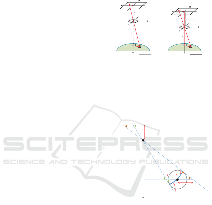
2.1 Observation System
Observation system of endoscope image is shown in
Fig.1 under the condition of point light source illu-
mination and perspective projection. Note that it is
assumed that the target object is continuous surface
with Lambertian reflectance and original RGB endo-
scope image is converted to the uniform Lambertian
reflectance.
Here the situation with using two images as shown
in Figure 1 is considered. The movement of ∆Z is as-
sumed from the correspondence of the observed med-
ical suture between two images. Although triangle
which forms the image coordinates x, y and focal
length f of the lens becomes similar as the triangle of
world coordinates X, Y and Z, absolute shape cannot
f
(x
2
, y
2
)
(Z - ΔZ)
(X, Y, Z - ΔZ)
x
y
X
Y
Z
Image Plane
Surface Element
Point Light Source
(0, 0, 0)
Lens
f
(x
1
, y
1
)
Z
(X, Y, Z)
x
y
X
Y
Z
Image Plane
Surface Element
Point Light Source
(0, 0, 0)
Lens
ΔZ
Model
1
Model2
Figure 1: Observation System.
be obtained without any calibration object in the im-
age. This paper uses the medical suture with known
width and proposes a new approach to estimate the
reflectance parameter C and the absolute shape of
polyp. Under the condition that the medical suture is
used as the reference object of scaling. Here, a cylin-
drical model of the medical suture is used for its cross
section as shown in Fig.1.
Thread
r
a
r
b
r = 0
Z
t
f
W
b
W
a
λ
b
λ
a
T
T
Image Plane
Point Light Source
(0, 0, 0)
Figure 2: Observation Model of Medical Suture.
2.2 Estimation of Movement ∆Z of
Camera along Depth Direction
Depth Z
t
is obtained for any point of the medical
suture based on the radius T of the medical suture
width. As there is a similarity between a triangle
of image coordinate (x, y, f ) and a triangle of world
coordinate (X,Y, Z), W
a
and W
b
are first obtained,
where W
a
and W
b
are necessary to calculate Z
t
. λ
a
is
represented from a triangle of image coordinate and
a triangle of radius of medical suture and tangent of
circumference as follows.
ICPRAM 2016 - International Conference on Pattern Recognition Applications and Methods
504

sinλ
a
=
f
p
r
2
a
+ f
2
sinλ
a
=
T
W
a
Solving this obtains W
a
. W
b
is obtained in the
same way.
W
a
=
T
f
q
r
2
a
+ f
2
(1)
W
b
=
T
f
q
r
2
b
+ f
2
(2)
The following relation is obtained using the simi-
larity of a triangle of the base (r
b
− r
a
) and the vertex
origin and that of the base (W
a
+W
b
) and the vertex
origin.
|r
b
− r
a
| : f = |W
a
+W
b
| : Z
t
Substituting Eq.(1)(2) into this can derive Z
t
as
follows.
Z
t
=
p
r
2
a
+ f
2
+
q
r
2
b
+ f
2
|r
b
− r
a
|
T (3)
Eq.(3) represents the depth estimation from one
image and this equation can be applied to the depth
Z
t1
of any point of the medical suture in image 1 and
the corresponding depth Z
t2
in image 2. The move-
ment of the camera should be ∆Z = Z
t1
− Z
t2
. How-
ever this depends on the width of medical suture on
the image plane and accuracy of corresponding point
between two images. The proposed approach tries to
obtain multiple candidate values of ∆Z using multiple
corresponding points between images and estimates
the best candidate value of camera movement param-
eter ∆Z along the depth direction. Let C
1
be a esti-
mated reflectance parameter for image 1, and let C
2
be that for image2. The best parameter ∆Z is selected
from the criteria which minimizes C
r
where C
r
is cal-
culated from Eq.(4) with the difference between C
1
and C
2
which is estimated from each image 1 and 2,
respectively.
C
r
=
|C
1
/C
2
| + |C
2
/C
1
|
2
− 1 (4)
2.3 Determining Initial Value C
init
Local brightest point is used to recover the 3-D shape
of polyp as an initial point. This is because initial
point has constraints where the surface normal vector
is the same direction as the light source vector under
the Lambertian reflectance. Here the approach first
converts into Lambertian image to recovers the 3-D
shape of polyp.
At the local brightest point under Lambertian re-
flectance, the relation of n and s
1
is n = s
1
and
(s
1
,n) = 1.
Let the image coordinate of the initial point in
image 1 be (x
1
,y
1
), let the corresponding coordinate
in image 2 be (x
2
,y
2
), and let the image intensity at
(x
1
,y
1
) be E
1
, then the initial candidate of reflectance
parameter C
init
can be given by
C
init
= E
1
(X
2
+Y
2
+ Z
2
)
=
E
1
Z
2
f
2
x
2
1
+ y
2
1
+ f
2
(5)
C
init
is derived by substituting Z into Eq.(5) af-
ter deriving Z geometrically using the corresponding
points between two images.
C
init
=
E
1
(∆Z)
2
{(1 − k
−
1
2
) f }
2
x
2
1
+ y
2
1
+ f
2
(6)
k =
q
(x
2
1
+ y
2
1
)(x
2
2
+ y
2
2
)
−1
C
init
can be uniquely determined by Eq.(6) and it
makes possible to obtain the actual scale of object to
be recovered.
3 EXPERIMENTS
Actual medical endoscope image is used in the ex-
periment. The original color image is converted into
Lambertian image in advance. The assumption of ob-
servation system is point light source illumination and
perspective projection. Image consists of 1000×870
pixels, the diagonal image size is 10mm, focal length
is 5mm and image density is 8-bits.
3.1 Obtaining Depth of Camera
Movement (Experiment 1)
Input images used in the experiment are shown in
Fig.3 and Fig.4, respectively.
Although it is necessary to extract the medical su-
ture region in the image, the region is manually ex-
tracted in this experiment (Experiment 1). The ex-
tracted result of medical suture region for Fig.3 and
Fig.4. Thinning processing is applied for the medical
suture region extracted and thinning process was used
for obtaining the gradient parameter ϕ of the medical
suture. The results of thinning processing are shown
in Fig.5 and Fig.6 with red part.
Next, the depth Z
t
of medical suture is derived
using Fig.5 and Fig.5. Coordinate of corresponding
Estimating Reflectance Parameter of Polyp using Medical Suture Information in Endoscope Image
505
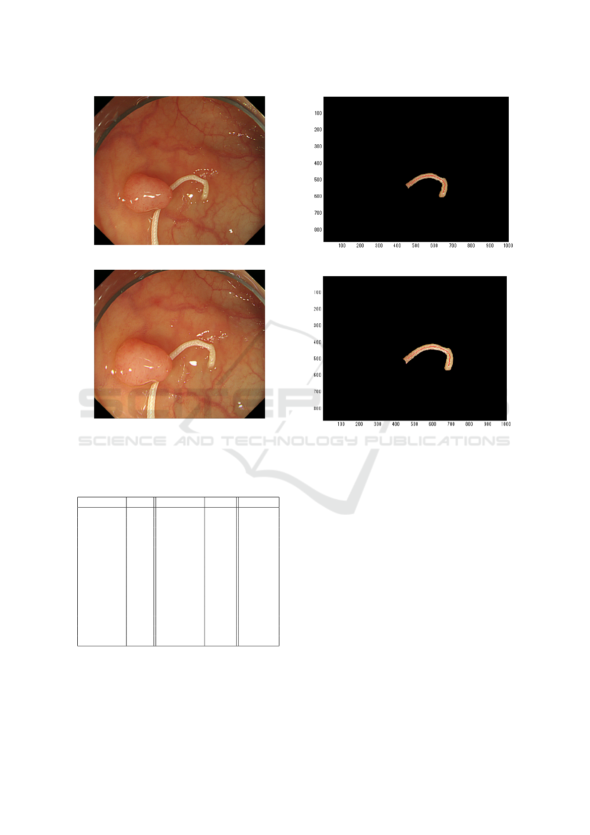
Figure 3: Input Image 1 (Experiment 1).
Figure 4: Input Image 2 (Experiment 1).
points (unit: pixel), depth Z
t
(unit: mm) and the error
of C
r
between images obtained from Eq.(4) is shown
in Table 1, respectively.
Table 1: Derived Parameter in Medical Suture Region.
(x
1
,y
1
) Z
t1
(x
2
,y
2
) Z
t2
C
r
(541, 685) 6.17 (581, 644) 6.82 0.0099
(453, 677) 4.04 (503, 644) 5.13 0.2904
(499, 462) 5.75 (528, 463) 84.50 94.3704
(452, 676) 4.04 (503, 644) 5.13 0.2904
(439, 570) 7.77 (484, 562) 7.70 0.1505
(414, 607) 6.96 (464, 586) 8.24 0.1766
(488, 681) 3.20 (533, 645) 4.59 0.5474
(439, 570) 7.77 (484, 562) 7.70 0.1505
(450, 543) 7.65 (488, 543) 8.79 0.1410
(544, 686) 6.33 (580, 646) 7.41 0.0786
(447, 670) 3.95 (497, 638) 4.49 0.0736
(431, 578) 7.78 (481, 546) 8.79 0.0871
(515, 692) 4.25 (557, 653) 7.39 0.9982
(454, 674) 2.68 (503, 641) 4.93 1.2090
Here it is shown that C
r
= 0.0099 gives the min-
imum value among 14 corresponding points between
images in Table 1. From this estimation,
∆Z = 6.82 − 6.17 = 0.65
Figure 5: Medical Suture Region of Image 1 (Experiment1).
Figure 6: Medical Suture Region of Image 2 (Experiment
1).
is estimated. This ∆Z is defined as camera movement
in the approach.
3.2 Result of 3D Recovered Shape
(Experiment 1)
Shape recovery is applied based on the approach pro-
posed in the previous papers (Tatematsu et al., 2013)
and (Iwahori et al., 2015a). Fig.3 is trimmed for polyp
region and gray scale image shown in Fig.7 is used
as experiment. Region outside of recovery is masked
with black and the object coordinates are kept for
the shape recovery. Here, Fig.7 represents converted
image to Lambert reflectance by removing specular
components with uniform reflectance parameter. In
the shape recovering process, surface gradient param-
eters (p,q) are optimized by introducing both photo-
metric and geometric constraints from the neighbor-
ing points starting from the local brightest point as an
initial point. Local brightest point has the property
that the light source direction vector becomes equal
to the surface normal vector under the assumption of
ICPRAM 2016 - International Conference on Pattern Recognition Applications and Methods
506
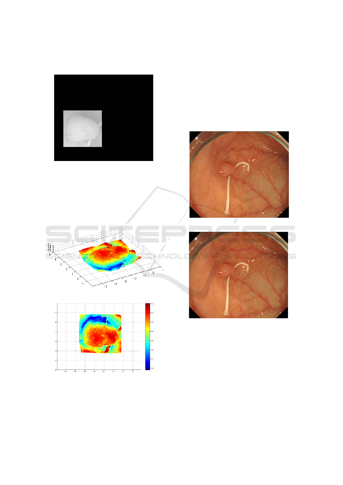
Lambertian reflectance. See paper (Tatematsu et al.,
2013) and (Iwahori et al., 2015a) for detail.
Figure 7: Test Object (Experiment 1).
Recovered results are shown in Fig.8 and 9. These
results are obtained from the different viewing angle
for the same 3D model and vertical size obtained is
around 2.7mm and horizontal size obtained is around
3.5mm. Medical suture region is also recovered but
there is no continuous region between the polyp re-
gion, and this region is not considered.
Figure 8: 3D Recovered Shape (Experiment 1).
Figure 9: 3D Recovered Shape (Experiment 1).
3.3 Obtaining Depth of Camera
Movement (Experiment 2)
Another experiment (Experiment 2) is done for the
video sequence using the near two frames which in-
cludes the medical suture. Input images used are
shown in Fig.10 and Fig.11, respectively. It is as-
sumed that image 2 is taken after image1. The final
purpose is to estimate the absolute size and shape of
polyp in images.
Figure 10: Input Image 1 (Experiment 2).
Figure 11: Input Image 2 (Experiment 2).
Difference of camera position of Fig.10 and that
of Fig.11 corresponds to the camera movement ∆Z
along Z-axis.
Extracted results for Fig.10 and Fig.11 and results
of thinning processing are shown in Fig.12 and Fig.13
with red part, respectively. These extractions are done
in the same way as Experiment 1.
Feature points are extracted by SIFT between two
images for Fig.12 and Fig.13. The purpose of in-
troducing SIFT is to obtain the corresponfing feature
points between two images. After extracting feature
points using SIFT, the depth Z
t
of medical suture is
obtained for each extracted point.
Estimating Reflectance Parameter of Polyp using Medical Suture Information in Endoscope Image
507
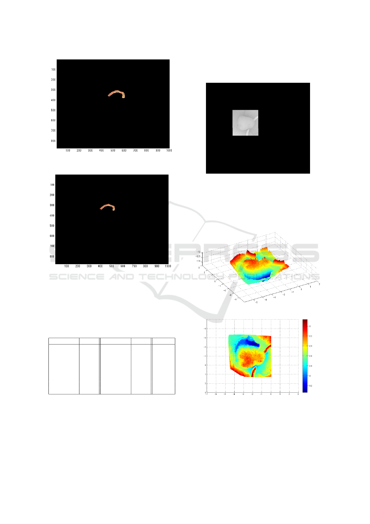
Figure 12: Medical Suture Region of Image 1 (Experi-
ment 2).
Figure 13: Medical Suture Region of Image 2 (Experi-
ment 2).
Coordinate of corresponding points (unit: pixel),
depth Z
t
(unit: mm) and the error of C
r
between im-
ages obtained from Eq.(4) is shown in Table 2, respec-
tively.
Table 2: Derived Parameter in Medical Suture Region (Ex-
periment 2).
(x
1
,y
1
) Z
t1
(x
2
,y
2
) Z
t2
C
r
(367, 592) 9.69 (341, 515) 8.41 0.2943
(345, 572) 10.26 (324, 500) 7.46 0.6720
(350, 468) 11.81 (328, 408) 12.08 0.1724
(329, 584) 4.55 (311, 511) 5.51 0.3921
(344, 573) 6.49 (324, 500) 7.46 0.2948
(353, 586) 5.07 (331, 511) 5.51 0.1730
(328, 507) 11.28 (307, 444) 13.37 0.4406
(336, 575) 10.26 (317, 503) 7.46 0.6720
Here it is shown that C
r
= 0.1724 gives the min-
imum value among 8 corresponding points between
images in Table 2. From this estimation,
∆Z = 12.08 − 11.81 = 0.27
is estimated. This ∆Z is used in the experiment 2.
3.4 Result of 3D Recovered Shape
(Experiment 2)
Figure 14: Test Object (Experiment 2).
Shape recovery was applied in the similar way as
in the previous experiment. Recovered results are
shown in Fig.15 and Fig.16. Similar values of hori-
zontal width and vertical width were obtained and the
result is almost close to the recovered result in exper-
iment 1.
Figure 15: 3D Recovered Shape (Experiment 2).
Figure 16: 3D Recovered Shape (Experiment 2).
4 CONCLUSION
This paper proposes a new approach to estimate the
camera movement ∆Z along the depth direction by
ICPRAM 2016 - International Conference on Pattern Recognition Applications and Methods
508

adding the medical suture as a calibration object with
known size. The approach essentially solved the
problem of treating the camera movement as known
constant under the condition that the original image
is converted to Lambertian image by removing spec-
ular reflectance with uniform reflectance parameter.
Based on estimating ∆Z, it makes possible to esti-
mate the reflectance parameter C and further to re-
cover the absolute size and shape of polyp based on
Shape-from-shading approach.
It is shown that the proposed approach is valuable
in the recovery process of polyp and the evaluation is
provided via experiments with real endoscope envi-
ronment. Using the medical suture as a calibration
object is not always useful but the paper extended
the possibility to recover the absolute size and shape
of polyp with further information. Further subject
includes that another cue information instead of the
medical suture is used and the entire purpose is done
with usual endoscope environment.
ACKNOWLEDEGEMENTS
Iwahori’s research is supported by Japan Society for
the Promotion of Science (JSPS) Grant-in-Aid for
Scientific Research (C) (26330210) and Chubu Uni-
versity Grant. The authors would like to thank the re-
lated lab member of Chubu University for their useful
discussions.
REFERENCES
Horn, B. K. P. (1975). Obtaining Shape from Shading In-
formation. In The Psychology of Computer Vision,
Winston, P. H. (Ed.), Mc Graw- Hill, pp. 115-155. Mc
Graw- Hill.
Iwahori, Y., Tatematsu, K., Nakamura, T., Fukui, S., Wood-
ham, R. J., and Kasugai, K. (2015a). 3D Shape Re-
covery from Endoscope Image Based on Both Pho-
tometric and Geometric Constraints. In Knowledge-
Based Information Systems in Practice, Smart Innova-
tion, Systems and Technologies, Springer, Vol.30, pp.
65-80.
Iwahori, Y., Tsuda, S., Woodham, R. J., Bhuyan, M., and
Kasugai, K. (2015b). Improvement of Recovering
Shape from Endoscope Images Using RBF Neural
Network. In ICPRAM 2015 (2), pp.62-70.
Mourgues, F., Devernay, F., and Coste-Maniere, E. (2001).
3D reconstruction of the operating field for image
overlay in 3D-endoscopic surgery. In Proceedings of
the IEEE and ACM International Symposium on Aug-
mented Reality (ISAR), pp. 191-192.
Nakatani, H., Abe, K., Miyakawa, A., and Terakawa, S.
(2007). Three-dimensional measuremen endoscope
system with virtual rulers. In Journal of Biomedical
Optics, 12(5):051803.
Neog, D. R., Iwahori, Y., Bhuyan, M. K., Woodham, R. J.,
and Kasugai, K. (2011). Shape from an Endoscope
Image using Extended Fast Marching Method. In Pro-
ceedings of IICAI-11, pp. 1006-1015. IICAI.
Tatematsu, K., Iwahori, Y., Nakamura, T., Fukui, S., Wood-
ham, R. J., and Kasugai, K. (2013). Shape from En-
doscope Image based on Photometric and Geometric
Constraints. In KES 2013, Procedia Computer Sci-
ence, Elsevier, Vol.22, pp. 1285-1293.
Thormaehlen, T., Broszio, H., and Meier, P. N. (2001).
Three-Dimensional Endoscopy. In Falk Symposium,
pp. 199-212.
Estimating Reflectance Parameter of Polyp using Medical Suture Information in Endoscope Image
509
