
Detection and Implementation Autonomous Target Tracking with a
Quadrotor AR.Drone
K. Boudjit
1
and C. Larbes
2
1
University of Science and Technology Houari Boumediene, USTHB, Algiers, Algeria
2
National School Polytechnic, ENP, Algiers, Algeria
Keywords: The Quadrotor, Ar.Drone, Hough Transform, Tracking, Flight Autonomous.
Abstract: Nowadays, There Are Many Robotic Applications Being Developed to Do Tasks Autonomously without
Any Interactions or Commands from Human, Therefore, Developing a System Which Enables a Robot to
Do Surveillance Such as Detection and Tracking of a Moving Object Will Lead Us to More Advanced
Tasks Carried out by Robots in the Future, AR.Drone Is a Flying Robot Platform That Is Able to Take Role
as UAV (Unmanned Aerial Vehicle), Usage of Computer Vision Algorithm Such as Hough Transform
Makes It Possible for Such System to Be Implemented on AR.Drone, in This Research, the Developed
Algorithm Is Able to Detect and Track an Object with Certain Shape, then the Algorithm Is Successfully
Implemented on AR.Drone Quadcopter for Detection and Tracking.
1 INTRODUCTION
In recent years, both remote controlled and
autonomously flying Miniature Aerial Vehicles
(MAVs) have become an important tool not only in
the military domain, but also in civilian
environments. Particularly quadcopters are
becoming more popular, especially for observational
and exploration purposes in indoor and outdoor
environments, but also for data collection, object
manipulation or simply as high-tech toys.
There are however many more potential
applications: A swarm of small, light and cheap
quadcopters could for example be deployed to
quickly and without risking human lives explore
collapsed buildings to find survivors. Equipped with
high-resolution cameras, MAVs could also be used
as flying photographers, providing aerial based
videos of sport events or simply taking holiday
photos from a whole new perspective.
Having a flying behavior similar to a traditional
helicopter, a quadrocopter is able to land and start
vertically, stay perfectly still in the air and move in
any given direction at any time, without having to
turn first. This enables quadrocopters - in contrary to
traditional airplanes - to maneuver in extremely
constrained indoor spaces such as corridors or
offices, and makes them ideally suited for stationary
observation or exploration in obstacle-dense or
indoor environments.
With the growing importance of MAVs however,
the quadrocopter design has become more popular
again. It is mechanically much simpler than a normal
helicopter as all four rotors have a fixed pitch.
Furthermore, the four rotors can be enclosed by a
frame, protecting them in collisions and permitting
safe flights indoors and in obstacle-dense
environments. Finally, the use of four rotors allows
each to have a smaller diameter, causing them to
store less kinetic energy during flight and reducing
the damage caused should the rotor hit an object,
making quadrocopters significantly safer to use
close to people.
Using mainly a single frontal camera for obstacle
detection and avoidance to enable fully autonomous
navigation on Micro Aerial Vehicles (MAVs) in
unknown areas is still a big challenge, although
camera is a desirable sensor for MAVs due to their
limited payload and power capabilities (Engel, 2012;
Dijkshoom, 2011). The frontal monocular camera
design is also common on commercial MAVs1.
Other sensors such as laser scanners are either heavy
or power hungry, hence not preferred for lightweight
MAVs in long-term navigation tasks. However,
latest achievements in MAV navigation either rely
on laser scanners (Linz, 2012), and known 3d maps
or use stereo cameras, but require human-specified
waypoints for collision-free trajectories (Lim, 2012).
223
Boudjit K. and Larbes C..
Detection and Implementation Autonomous Target Tracking with a Quadrotor AR.Drone.
DOI: 10.5220/0005523102230230
In Proceedings of the 12th International Conference on Informatics in Control, Automation and Robotics (ICINCO-2015), pages 223-230
ISBN: 978-989-758-123-6
Copyright
c
2015 SCITEPRESS (Science and Technology Publications, Lda.)
Micro Aerial Vehicles (MAVs) are increasingly
regarded as a valid low-cost alternative to UAVs and
ground robots in surveillance missions and a number
of other civil and military applications. Research on
autonomous MAVs is still in its infancy and has
focused almost exclusively on integrating control
and computer vision techniques to achieve reliable
autonomous flight. In this paper, we describe our
approach to using automated planning in order to
elicit high-level intelligent behaviour from
autonomous MAVs engaged in surveillance
applications. Planning offers effective tools to
handle the unique challenges faced by MAVs that
relate to their fast and unstable dynamics as well as
their low endurance and small payload capabilities.
We demonstrate our approach by focusing on the
“Parrot AR.Drone2.0” quadcopter and Search-and-
Tracking missions, which involve searching for a
mobile target and tracking it after it is found.
In this paper, we propose using an AR.Drone to
produce a solution to an autonomous search and
tracking the target.
We demonstrate our approach by focusing on the
“Parrot AR.Drone2.0” quadcopter and Search-and-
Tracking missions, which involve searching for a
mobile target and tracking it after it is found.
paper will be part of the conference proceedings
therefore we ask that authors follow the guidelines
explained in this example and in the file
«FormatContentsForAuthors.pdf» also on the zip
file, in order to achieve the highest quality possible.
Be advised that papers in a technically unsuitable
form will be returned for retyping. After returned the
manuscript must be appropriately modified.
2 HARDWARE AND SOFTWARE
DESIGN
The ARDrone quadrotor (called a drone) from Parrot
(ardrone2, 2014) is a consumer grade product which
is low cost and easy to use. It comes with an \indoor
hull", which covers the propellers and can therefore
be safely used indoors. All parts of this quadrotor
are replaceable including the onboard computer. It is
well built and can survive some serious crashes.
The onboard computer is Wi-Fi enabled, which
makes it easy to control the quadrotor with any Wi-
Fi enabled devices such as smart phones, tablets and
PCs. The firmware and hardware onboard are
closed. However, it comes with a Software
Development Kit (SDK) which gives easy access to
sensor data and control software onboard. The
software development kit has been continuously
evolving since its initial release. There is an active
community (ardrone2, 2014) of users and
developers.
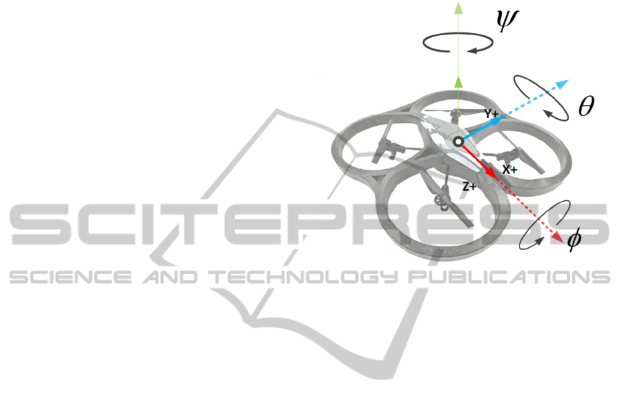
Figure 1: Quadrotor coordinate system.
The onboard computer uses the inertial sensors
(accelerometer and gyrometers) for stabilization
(low level control) along with downward looking
camera which provides velocity estimates of the
quadrotor in XY plane of the quadrotor body-fixed
frame using optical flow. The flight time of the
quadrotor is poor (only 9 min).
The software developed in this work consists of
independently running processes. These processes
communicate with each other in an event driven
architecture based on message passing. This kind of
modular architecture is worth during and after
system development.
In fact, with this approach it is possible to break
a complex problem (such as exploration problem)
into simpler tasks making easier to update, debug
and modify every single part of the system.
Moreover, it allows interoperability with other
packages and easier future enhancements.
We have chosen Robot Operating System (ROS)
(ROS, 2015) as software platform in line with our
idea to develop a system as modular as possible.
ROS is a framework and a toolbox for the
development of robot applications. The framework
has a lot of features including hardware abstraction,
device drivers, libraries, visualises and the
aforementioned message-passing. The Toolbox is
very extensive and we have used many utilities from
it. Some important ROS tools and packages for our
work are RViz , rosbag, pcl ros, ardrone driver and
tum ardrone. RViz is a 3D visualisation tool. The
ICINCO2015-12thInternationalConferenceonInformaticsinControl,AutomationandRobotics
224
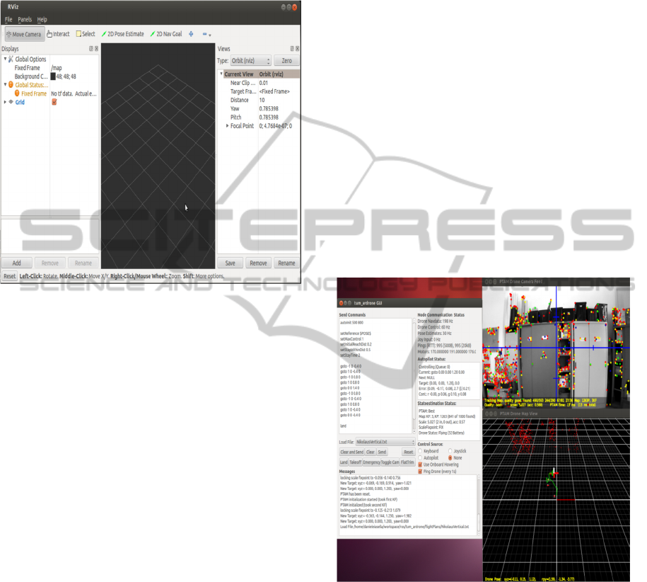
strong point of this tool is that it can display much
kind of messages, like pose or point positions, as
soon as they are published. In figure 2 it is possible
to see an empty view of the visualised.
Figure 2: RViz Window.
rosbag is a package of tools for recording
messages from and playing back them to ROS
topics. It is a useful debugging instrument during the
development life cycle of a project. It allows to
record a pack of all the needed messages for the
correct operation of the developed system and to
make tests in safety conditions in a different
afterwards.
ardrone autonomy, fork of AR-Drone Brown
driver is a ROS driver for Parrot AR.Drone. The real
advantage is all client-drone communications are
translated in ROS topic and ROS service. To read
data from drone developer can implement a
subscriber to ardrone/navdata topic. In this topic,
ardrone autonomy publishes an on purpose
message11 containing navdata of drone. Sending
commands to AR-Drone may be categorised in two
classes. In order to allow the drone to take o_, land
or emergency stop/reset we have to publish an
empty12 message to ardrone/takeoff, ardrone/land
and ardrone/reset topic respectively. Once the
quadrotor is flying we can publish a message13 to
the cmd_vel topic to move it. Messages published to
cmd_vel are translated in terms of pitch, roll and
yaw angles by driver of AutonomyLab.
tum ardrone is a package developed for Parrot
AR.Drone and AR.Drone 2.0. This system enables a
low-cost quadrocopter coupled with a laptop to
navigate autonomously, after fixed coordinates, in
previously unknown environments without GPS
sensor. The package consists of three components: a
monocular SLAM system based on PTAM
algorithm, an extended Kalman filter for position
estimation and data fusion and a steering commands
generator based on PID controller (control node).
Concerning the operation of the package under
consideration it is possible to control the drone
through a graphical user interface (shown in figure
3). The interface allows users to create custom
scripts containing positions in terms of three
dimensional coordinates and angle of rotation that
describe the path the drone has to follow. To localize
the camera of the drone and to map the environment
we choose to use PTAM system coupled with an
Extended Kalman Filter. Therefore, we have chosen
to use this package as base of our SLAM system
since it implements the original implementation of
PTAM system suited to work with the AR.Drone
camera and an Extended Kalman Filter that
computes the reliable position of the drone in case of
PTAM failures.
Figure 3: Tum Ardrone Interface.
3 SYSTEM OVERVIEW AND
METHODOLOGY
Object detection is one of important fields in
computer vision. The core of object detection is
recognition of an object in images precisely.
Applications such as image search or recognition use
object detection method as its main part. Today,
object detection problem is still categorized as open
problem because of the complexity of the image or
DetectionandImplementationAutonomousTargetTrackingwithaQuadrotorAR.Drone
225
the object itself (Lim, 2012). The common approach
to detect object in videos is using the information
from each frame of the video. But, this method has
high error rate. Therefore, there are some detection
methods that use temporary information computed
from sequence of frames to reduce the detection error
rate (Mohong, 2012).
Object tracking, just like object detection, is one
of important fields in computer vision. Object
tracking can be defined as a process to track an
object in a sequence of frames or images. Difficulty
level of object tracking depends on the movement of
the object, pattern change of the object and the
background, changing object structure, occlusion of
object by object or object by background, and camera
movement. Object tracking is usually used in high-
level application context that needs location and
shape of an object from each frame [AutonomyLab,
2014]. There are three commonly known object
tracking algorithms, Point Tracking, Kernel
Tracking, and Silhouette Tracking. Examples of
object tracking application are traffic surveillance,
automatic surveillance, interaction system, and
vehicle navigation.
In the problems we consider in this paper, the
observer is the AR.Drone and the target is a person
or any object that moves according to its own
intentions and proceeds at a speed compatible with
the speed of the drone. We assume that the target
needs to reach a specific destination within a
confined known area, which might be outdoors or
indoors, and chooses an efficient path to do so. In
addition, the target does not perform evasive actions
by attempting to use features in the environment for
concealment. This is a plausible assumption as the
target might be cooperating with the drone or simply
unaware of its presence. As we do not deal with
object recognition, we assume that the target is
identified by a specific tag known in advance by the
drone, although the drone might fail to observe the
target even when it is in view due to its noisy
sensors. Finally, we are interested in long-term SaT
missions in wide areas, relative to the scale of the
drone.
In this research, development of an autonomous
detection and tracking system of an object using
AR.Drone is conducted. The term autonomous
means the system can detect and track object
independently without interactions from user/human.
Detection means the robot is able to recognize
certain object using its sensors. Tracking means
robot is able to follow the said object movement.
AR.Drone has two cameras, frontal camera and
vertical camera. This research is focused on usage of
computer vision algorithm as the base of the
developed system. Therefore, object detection is
carried out using AR.Drone frontal camera as the
main sensor.
Being a robot for toy, AR.Drone has limits in
computational capacity. Meanwhile, the image
processing with computer
Vision algorithm needs pretty high resources.
With that concern, all computations executed in this
system are conducted in a computer connected to the
AR.Drone wirelessly.
Object detection program receives image or video
stream from AR.Drone camera. Every frame of the
video stream is processed one by one by the program.
The computer vision algorithm will process the
image and gives object information as output. For
example the detected object is a blue. If the object is
not found, no output is given.
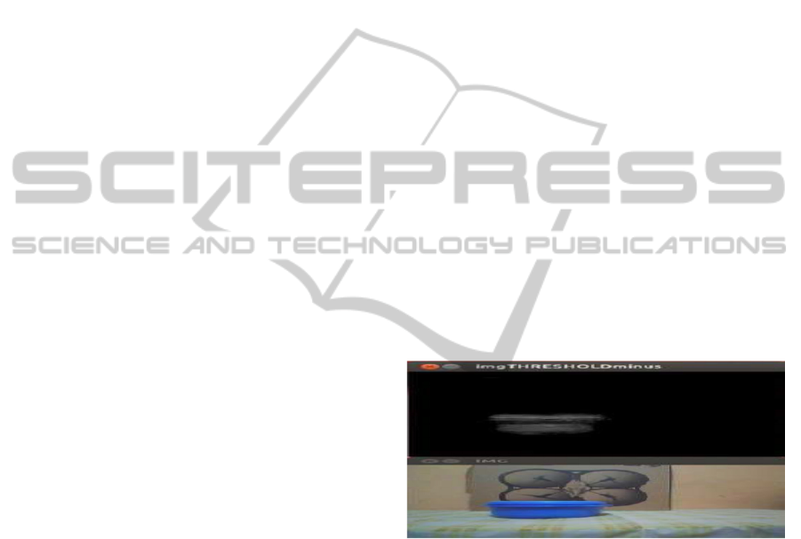
For an easier but intuitive application, we chose
to use the AR Drones bottom camera to help the
drone park by itself. We have crossed blue lines on
the ground; the AR Drone starts from a point further
from the crossed point. It first detect the straight
lines and find the center (average) of the blue pixels,
it provides feed back to the AR Drone control
system which moves the AR Drone in real-time. The
figure 4 shows the result of the camera drone.
Figure 4: Detecting blue colour with AR.Drone camera.
To allow the drone to carry out a tracking mission
autonomously, we combine the abstract deliberative
skills with low-level control and vision capabilities.
We implemented different techniques for the two
phases of a tracking mission. We first give an
overview of them and then provide additional details
on their implementation.
Tracking Phase
Tag recognition: Since we assume that our target is
identified by a specific tag, the drone needs to be
able to recognise tags from a distance based on the
video stream coming from its cameras. We use
computer vision algorithms to solve this problem.
The following figure 5 shows a tag tracking using
AR.Drone.
ICINCO2015-12thInternationalConferenceonInformaticsinControl,AutomationandRobotics
226
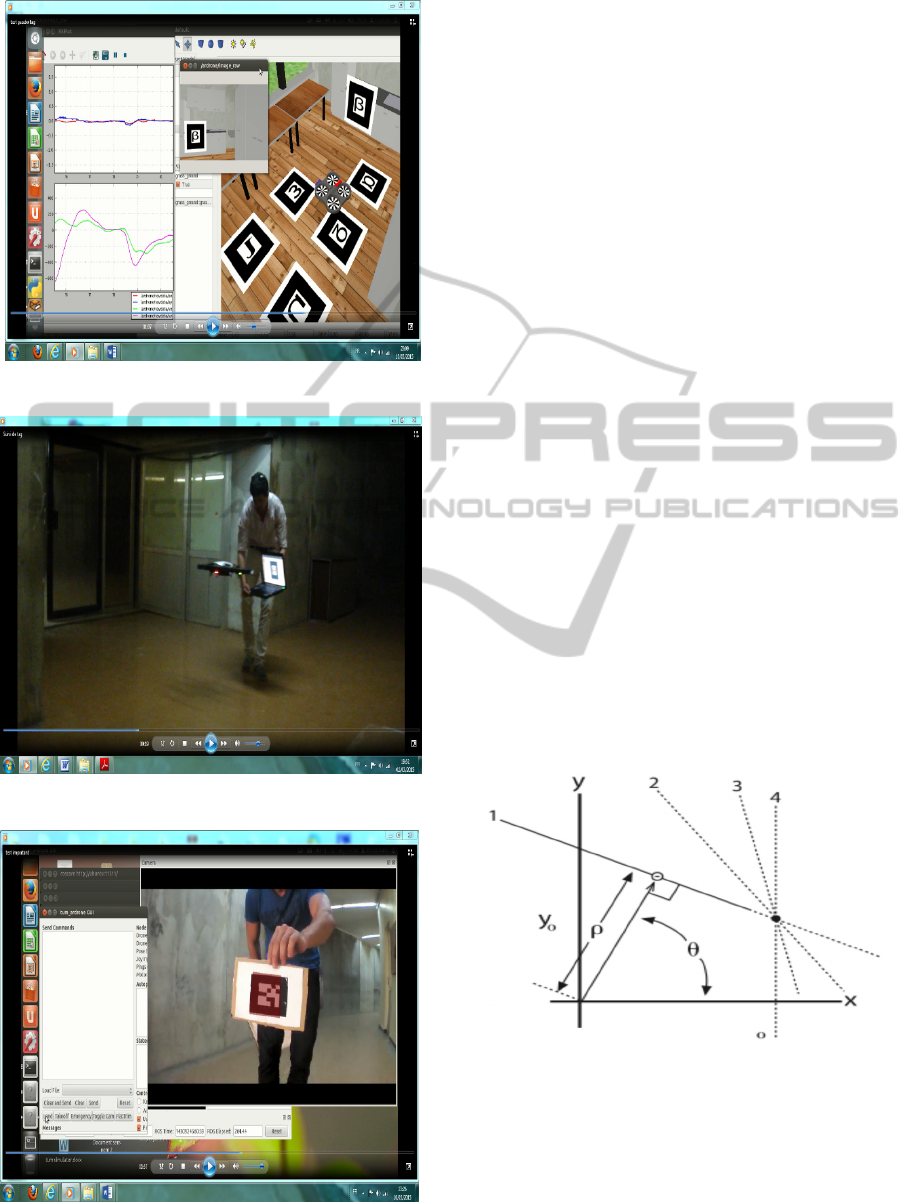
Figure (5a): Simulation result in Gazebo.
Figure (5b): Experimental result for tracking.
Figure 6: Experimental result for tracking markers.
Tag following: Once the drone has recognised the
tag identifying the target, it needs to follow it
reactively. We achieve this by implementing a
Proportional-Integral- Derivative (PID) controller
that works based on the navigation data provided by
the drone’s driver. The following figure 6 shows a
markers tracking using AR.Drone.
Search Phase
The AR.Drone provides built-in low-level control
for robust flight, such as stabilisation and attitude
maintenance, so we focus on high-level control only.
Since we currently ignore obstacle avoidance, our
implementation provides capabilities for localisation
and mapping, navigation and compensation for drift.
The navigation system that we use is composed of: a
monocular SLAM implementation for visual
tracking, an Extended Kalman Filter (EKF) for data
fusion and prediction, and a PID control for pose
stabilisation and navigation.
- Line detection: To get the extracted crop row out
of the detected pixels a line should be fitted. The
fitted line is described by specific parameters.
The detection of the perspective lines has been done
using the Hough transform algorithm which use a
voting scheme procedure to find the lines that lie
more close to some points exported by the Canny
detector. In order to accomplish that, we use the
polar-coordinates where each line is expressed with
a unique (
,
) , and a generic point (x,y)
belongs to that line if satisfy the equation 1.
sincos yx
(1)
Figure 7: Each straight line has a unique representation in
polar-coordinates (
,
).
Where
,
represents the distance of a line from
the origin and
is the angle among the x-axis
(figure 6).
Thereafter we use Progressive Probabilistic
DetectionandImplementationAutonomousTargetTrackingwithaQuadrotorAR.Drone
227
Hough transform (PPHT) for line detection, the
algorithms will be implemented on the drone
AR.Drone using the front camera. This method is a
variation of the standard Hough transform. It takes
in the extent of the lines than just the orientation of
the lines. The reason its called Probabilistic is that
accumulates only a fraction of the points in the
accumulator plane and not all of them.
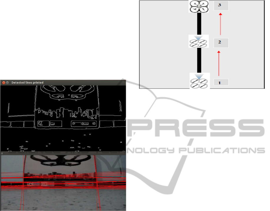
(source:Learning OpenCv). Figure 8 shows is a
picture of line detection using probabilistic Hough
transform.
Figure 8: Picture of line detection using PPHT.
In this work we wrote the code for probabilistic
Hough transform. But one has to know, how to make
use of the lines extracted, in the next experience we
have designed basic navigation algorithm based on
probabilistic Hough transform.
This shows the application of Hough line
detection. For the target to be followed by quadrotor,
we chose a straight line. Subsequently, we
implemented our program on the AR.Drone. The
main goal must be that the drone follows the line
throughout the flight automatically. For the tracking
of the line, our quadrotor uses the camera. Figure 9
shows an example of a capture camera on board the
UAV (AR.Drone) for target tracking (line). Figure 9
shows, the line following principle.
Figure 9: Line following principle.
4 EXPERIMENTAL RESULT AND
PERFORMANCE ANALYSIS
There are two scenarios designed for experiments in
this research. The first scenario tests how well
AR.Drone can detect and approach the object.
Second scenario is similar to the first scenario, but
the AR.Drone does not directly face the object.
In order to control the drone we use a PID
controller, taking the predicted drone state for T3 as
input. In particular we directly use the speed
estimates. Let
T
zyxzyxx ),,,,,,,,,(
....
be the predicted state of the drone, and
T
zyxP ),,,(
the target position and yaw
angle. The control signal
),,,(
..
zu
is now
calculated by applying PID control to these four
parameters, and rotating the result horizontally such
that it corresponds to the drone’s coordinate system:
sin)32.0)(5.0(cos)32.0)(5.0(
..
yyyxxx
cos)32.0)(4.0(sin)32.0)(5.0(
..
yyyxxx
))(01.01.0)(6.0
..
zzzzzz
)(02.0
.
We found that integral control is only required for
controlling the drone’s height, while the yaw angle
can be controlled by a proportional controller alone
without resulting in oscillations or overshoot. The
integral term for the height control is reset when the
target height is first reached, and capped at a
maximum of 0.2. The other parameters were
determined experimentally.
ICINCO2015-12thInternationalConferenceonInformaticsinControl,AutomationandRobotics
228
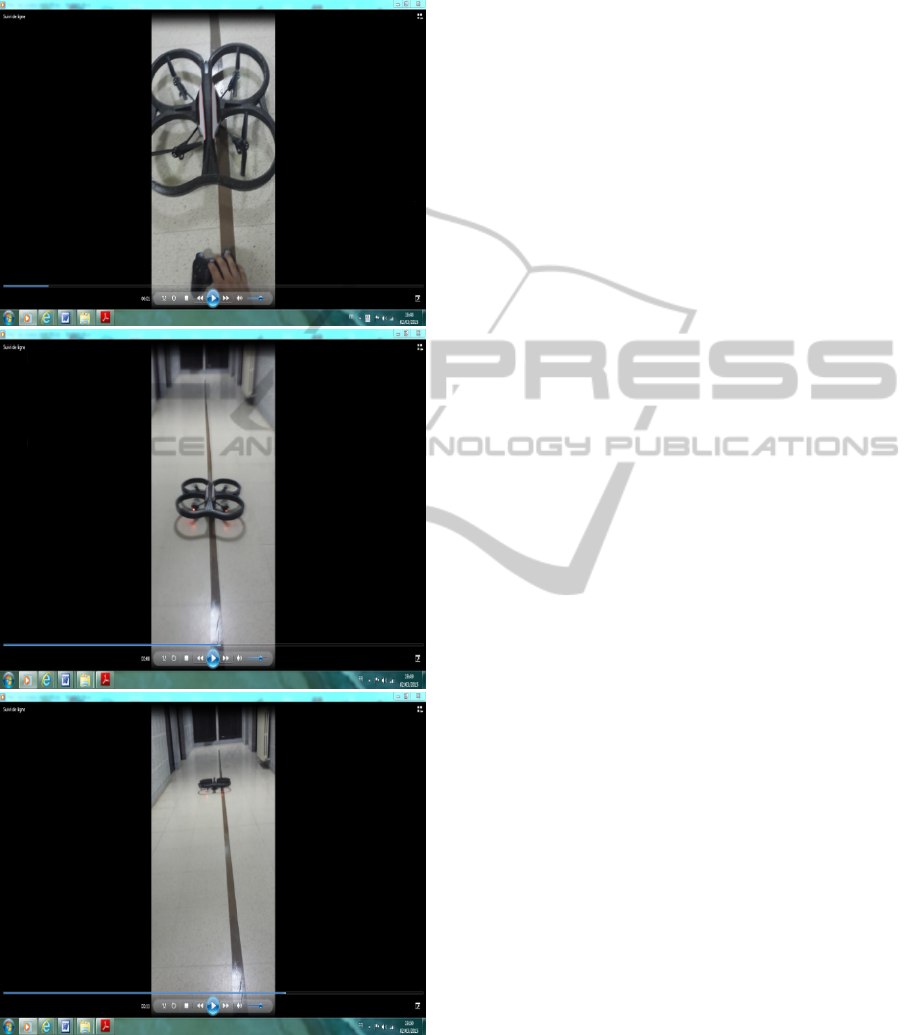
Figure 10, shows the tracking of a line using
quadrotor AR.Drone.
Figure 10: Experimental test for the tracking line using
AR.Drone.
The figures 10 above show how the system can
detect the object in different environment settings.
Simple environment means there’s little to zero
noise or any other objects with same color or shape.
Complex environment means there’s some noises.
If the Hough transform introduces a delay the
process time can be speeded up by applying a
horizontal region of interest (ROI), instead of a
vertical region of interest. A vertical ROI is very
sensitive for fast changes in the position of the
drone. External influences, like the wind, make the
drone sensitive for fast movements. A horizontal
ROI can solve this problem; a drawback is the
stability of the line recognition. Due to the small
stripe, the offset and the angle can fluctuate more
compared with the vertical ROI.
Normally the range of theta is from
till
radians. To speed up the Hough transform the
range of theta is decreased A smaller range reduces
the calculation time but makes the algorithm more
sensitive to fast changes in orientation.
5 CONCLUSIONS
The drone was able to follow the line, able to predict
the turn and also to make a turn on the corners. This
research can be further developed and used for many
applications. The one can be auto guidance system
for customer in a mall or retail business. We can
make lines of different colors on the ground in the
whole building and if a customer demanded
something we can just ask them to follow the drone.
The drone will then follow a predefined path of
colors or corners.
In the future works, the real time running must
be done in various heights and in the outdoor.
Besides that, the object recognition must be
developing to track or detect more objects. The
development of swarm robots is also one of the
greatest challenges in the future. Hopefully those
works can be done in the near future.
REFERENCES
Engel, J. J. Sturn, and D. Gremers. (2012). Camera-Based
Navigation of a Low-Cost Quadrocopter In Proc. Of
the International Conference on Intelligent Robot
Systems (IROS).
Dijkshoorn, N. and A. Visser J. (2011). Integrating Sensor
and Motion to Localize an Autonomous AR.Drone
Universiteit Van Amsterdam, International Journal of
Micro Air Vehicles.
Linz, A and A. Ruckelshausen. (2012). Educational
Robotic Platform “Zero2Nine” for Autonomous
Navigation and Tracking Based on Imaging Sensor
DetectionandImplementationAutonomousTargetTrackingwithaQuadrotorAR.Drone
229

Systems. in 3
rd
International Conference on Machine
Control & Guidance, March 27-29, 2012.
Grade.V. H. H. Bulthoff, and P. Robuffo Giordano.
(2012). On-Board Velocity Estimation and Closed-
Loop Control of a Quadrotor UAV Based on Optical
Flow, In 2012 IEEE Int, Conf, On Robotics and
Automation, pages 491-497, St, Paul, MN, May 2012.
Gilluda, J. H., and C. J. Tomlin. (2012). Guaranteed Safe
Online Learning via reachability: tracking a Ground
Target Using a Quadrotor. In Robotics and
Automations (ICRA), 2012 IEEE International
Conference on, pages 2723-2730.
Grale. V, M. Riedel. H. H. Bulthoff, P. Robuffo Giodano,
and A. franchi. (2013). The Telekyb framework for a
Modular and Extensible ROS-Based Quadrotor
Control. In 6
th
European Conference on Mobile
Robots, Barcelona, Spain, Sep 2013.
Lim. H. J. Park, D. Lee, and H. J. Kim. (2012). Build Your
Own Quadrotor: Open-Source Projects on Unmanned
Aerial Vehicles. IEEE Robotics & Automation
Magazine, 19(3): 33-45, 2012.
Mahong. R. V. Kumar, and P. Corke. (2012). Multirotor
Aerial Vehicles Modeling Estimation and Control of
Quadrotor. IEEE Robotics & Automation Magazine
19(3): 20-32, 2012.
AutonomyLab (2014). https://github.com/AutonomyLab/
ardrone_autonomy/, last accessed: 2015-01-26.
Parrot (2014). http://ardrone2.parrot.com/, last accessed :
2015-02-15.
Ros (2015). www.ros.org/, Last accessed: 2015-03-13.
ICINCO2015-12thInternationalConferenceonInformaticsinControl,AutomationandRobotics
230
