
Formal Analysis of Sequence Diagram with Combined Fragments
Hui Shen, Mark Robinson and Jianwei Niu
Department of Computer Science, University of Texas at San Antonio, San Antonio, Texas, U.S.A.
Keywords:
Modeling, Model Checking, Sequence Diagram, Concurrency & Communication.
Abstract:
The Combined Fragments of UML Sequence Diagram permit various types of control flow among messages
(e.g., interleaving and branching) to express an aggregation of multiple traces encompassing complex and
concurrent behaviors. However, Combined Fragments increase the difficulty of Sequence Diagram compre-
hension and analysis. To alleviate this problem, we introduce an approach to formally describe Sequence
Diagrams with Combined Fragments in terms of the input language of the model checker NuSMV. This ap-
proach permits the verification of desired properties against Sequence Diagrams.
1 INTRODUCTION
In software development process, models enable soft-
ware engineers to detect errors during early stage so
as to improve the system quality. Scenario-based
models have been widely employed for the descrip-
tion of interactions among environmental actors (e.g.,
human beings) and the components (aka Lifeline) of
the software systems through the exchange of mes-
sages. UML Sequence Diagrams, which graphically
depict scenarios, serve as well-accepted and intuitive
media among software engineers and tool builders.
UML 2 provides many major structural control con-
structs, including Combined Fragments and Interac-
tion Use, to allow multiple, complex scenarios to be
aggregated in a single Sequence Diagram. However,
Combined Fragments introduce concurrentbehaviors,
making analysis of the Sequence Diagrams difficult
for the following reasons.
Combined Fragments permit different types of
control flow, such as interleaving and branching, in-
creasing a Sequence Diagram’s expressiveness. Fur-
ther, the Combined Fragments can also be nested to
provide more complex control flows. These make it
difficult to predict what behavior are represented. For
example, if a Combined Fragment presenting branch-
ing behavior is nested within a Combined Fragment
presenting iteration behavior, different choices may
be made in different iterations. The semantics of Se-
quence Diagram with Combined Fragments is not for-
mally defined compared to their precise syntax de-
scriptions (Object Management Group, 2011), mak-
ing it is hard to derive the traces from Sequence Dia-
grams. Thus, subtle errors from concurrency can eas-
ily be introduced to Sequence Diagrams to evade dis-
covery via manual inspection.
To address these problems, we introduce an au-
tomated technique to facilitate the verification of Se-
quence Diagrams by leveraging the analytical powers
of model checking. Working towards similar goals,
many researchers have verified different scenario-
based models, including Sequence Diagram, Message
Sequence Chart (MSC), and Live Sequence Chart
(LSC). However, the previous work does not con-
sider all the aspects of Combined Fragments. Our
approach supports all the features of Combined Frag-
ments, including all 12 Interaction Operators, nested
Combined Fragments, both asynchronous and syn-
chronous Messages, and Interaction Constraints.
We devise an approach to codify the semantics
of Sequence Diagrams and Combined Fragments in
the input language of NuSMV by deconstructing Se-
quence Diagrams and Combined Fragments to obtain
fine-grained syntactic constructs (see section 2 and
3). We formally describe each Combined Fragment in
terms of NuSMV (Cimatti et al., 2000) modules (see
section 4). The model checking mechanism can ex-
plore all possible traces specified in the Sequence Di-
agram, verifying if the desired properties are satisfied.
We have developed a tool suite to implement all of the
techniques and have validated our technique by ana-
lyzing and discovering violations in two design exam-
ples taken from an insurance industry software appli-
cation (see section 5). We have also created an Oc-
currence Specification Trace Diagram generator that
automatically produces Sequence Diagram visualiza-
44
Shen H., Robinson M. and Niu J..
Formal Analysis of Sequence Diagram with Combined Fragments.
DOI: 10.5220/0004076800440054
In Proceedings of the 7th International Conference on Software Paradigm Trends (ICSOFT-2012), pages 44-54
ISBN: 978-989-8565-19-8
Copyright
c
2012 SCITEPRESS (Science and Technology Publications, Lda.)

tions from NuSMV-produced counterexamples. This
automation will increase the accessibility of our ap-
proach by allowing software engineers to remain fo-
cused in the realm of Sequence Diagrams.
2 UML 2 SEQUENCE DIAGRAM
In this section, we outline the syntax and semantics of
a Sequence Diagram with Combined Fragments pro-
vided by OMG (Object Management Group, 2011).
As the first step of defining a Sequence Diagram us-
ing NuSMV modules, we precisely define the seman-
tics of Sequence Diagram with Combined Fragments,
forming the basis of expressing the semantics in term
of NuSMV models. We begin with the basic Se-
quence Diagram, then discuss the structured control
constructs, including Combined Fragments and Inter-
action Use.
2.1 Basic Sequence Diagram
We refer to a Sequence Diagram without Combined
Fragments as a basic Sequence Diagram (see figure 1a
for an example with annotated syntactic constructs).
A Lifeline is a vertical line representing a participat-
ing object. A horizontal line between Lifelines is a
Message. A Message is the specification of an oc-
currence of a message type within the Sequence Di-
agram, while a message type is the signature of the
form hmessage name, source Lifeline, target Lifelinei.
Within a Sequence Diagram, a message type can oc-
cur multiple times, which are associated with multi-
ple Messages. Each Message is sent from its source
Lifeline to its target Lifeline and has two endpoints.
Each endpoint is an intersection with a Lifeline and is
called an Occurrence Specification (OS), denoting
the specification of an occurrence of an event within
a certain context, i.e., a Sequence Diagram. Accord-
ingly, multiple OSs within a Sequence Diagram can
be associated with an event. Each Message is de-
fined by its sending OS and receiving OS. We asso-
ciate each OS with a location of a Lifeline. As each
location is uniquely defined, each OS is uniquely de-
fined. Thus, each Message is uniquely defined by its
sending OS and receiving OS. OSs can also be the
beginning or end of an Execution Specification, indi-
cating the period during which a participant performs
a behavior within a Lifeline, which is represented as
a thin rectangle on the Lifeline.
The semantics of a basic Sequence Diagram is de-
fined by a set of traces. A trace is a sequence of OSs
expressing Message exchange among multiple Life-
lines. We identify four orthogonal semantic aspects
that must be considered for the basic Sequence Dia-
gram (Micskei and Waeselynck, 2011; Object Man-
agement Group, 2011; Kugler et al., 2005)
1. Each OS can execute only once, i.e., each OS is
unique within a Sequence Diagram.
2. On each Lifeline, OSs execute in their graphical
order from top to bottom.
3. For a single Message, the sending OS must take
place before the receiving OS does.
4. In a Sequence Diagram, only one object can exe-
cute an OS at a time, i.e., OSs on different Life-
lines are interleaved.
Messages are of two types: asynchronousand syn-
chronous. The source Lifeline can continue to send or
receive other Messages after an asynchronous Mes-
sage is sent. If a synchronous Message is sent, the
source Lifeline blocks until it receives the target Life-
line’s response (Object Management Group, 2011).
2.2 Combined Fragment
Both Combined Fragments and Interaction Use are
structured control constructs introduced in UML 2. A
Combined Fragment (CF) is a solid-outline rectan-
gle, which consists of an Interaction Operator and
one or more Interaction Operands. Figure 1b shows
example CFs with annotated syntactic constructs. A
CF can enclose all, or part of, Lifelines in a Sequence
Diagram. The Interaction Operands are separated by
dashed horizontal lines. The Interaction Operator is
shown in a pentagon in the upper left corner of the
rectangle. OSs, CFs, and Interaction Operands are
collectively called Interaction Fragments. An In-
teraction Operand may contain a boolean expression
which is called an Interaction Constraint or Con-
straint. An Interaction Constraint is shown in a square
bracket covering the Lifeline where the first OS will
happen. BEU, HEU and CEU are defined in Section
3. An Interaction Use construct allows one Sequence
Diagram to refer to another Sequence Diagram. The
referringSequence Diagram copies the contents of the
referenced Sequence Diagram.
We identify three independent semantic rules gen-
eral to all CFs, in the sense that these rules do not
constrain each other.
1. OSs and CFs, are combined using Weak Sequenc-
ing (defined below). On a single Lifeline, a CF’s
preceding Interaction Fragment must complete
the execution prior to the CF’s execution, and the
CF’s succeeding Interaction Fragment must exe-
cute subsequently.
FormalAnalysisofSequenceDiagramwithCombinedFragments
45
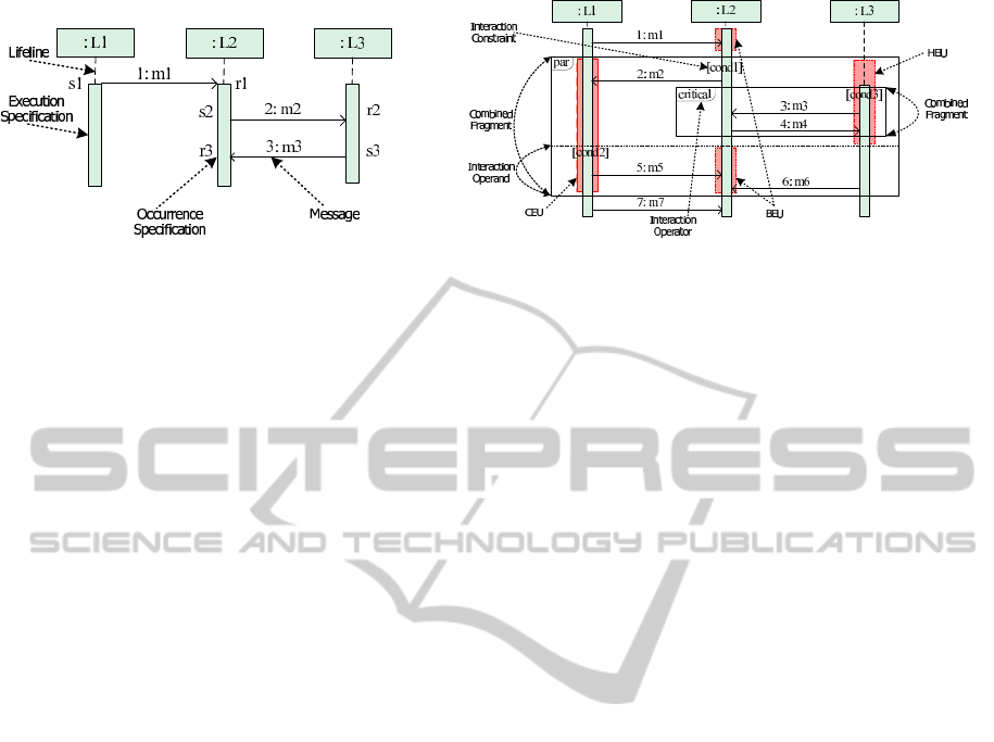
(a) Basic sequence diagram. (b) Sequence diagram with combined fragment.
Figure 1: Sequence diagram syntax.
2. Within a CF, the order of the OSs and CFs within
each Operand is maintained if the Constraint of
the Operand evaluates to True; otherwise, the
Operand is excluded.
3. The CF does not execute when the Constraints of
all the Operands evaluate to False. Thus, the CF’s
preceding Interaction Fragment and succeeding
Interaction Fragment are ordered by Weak Se-
quencing.
2.3 Interaction Operator
The semantics of each CF Operator determinesthe ex-
ecution order of all the Operands. Each Operator has
its specific semantic implications regarding the exe-
cution of the OSs enclosed by the CF on the covered
Lifelines. The Operators are summarized as follows:
Alternatives: one of the Operands whose Interaction
Constraints evaluate to True is nondeterministically
chosen to execute. Option: its sole Operand executes
if the Interaction Constraint is True. Break: its sole
Operand executes if the Interaction Constraint evalu-
ates to True. Otherwise, the remainder of the enclos-
ing Interaction Fragment executes. Parallel: the OSs
on a Lifeline within different Operands may be in-
terleaved, but the ordering imposed by each Operand
must be maintained separately. Critical Region: the
OSs on a Lifeline within its sole Operand must not be
interleaved with any other OSs on the same Lifeline.
Loop: its sole Operand will execute for at least the
minimum count (lower bound) and no more than the
maximum count (upper bound) as long as the Interac-
tion Constraint is True. Assertion: the OSs on a Life-
line within its sole Operand must occur immediately
after the preceding OSs. Negative: its Operand rep-
resents forbidden traces. Strict Sequencing: in any
Operand except the first one, OSs cannot execute until
the previous Operand completes. Weak Sequencing:
on a Lifeline, the OSs within an Operand cannot exe-
cute until the OSs in the previous Operand complete,
the OSs from different Operands on different Lifelines
may take place in any order (cf. Strict Sequencing).
Consider: any message types other than what is spec-
ified within the CF is ignored. Ignore: the specified
messages types are ignored within the CF.
The semantics of the seq Sequence Diagram is de-
fined by two sets of traces, one containing a set of
valid traces, denoted as Val(seq), and the other con-
taining a set of invalid traces, denoted as Inval(seq).
The intersection of these two sets is empty, i.e.,
Val(seq) ∩ Inval(seq) =
/
0.
3 SEQUENCE DIAGRAM
DECONSTRUCTION
To facilitate codifying the semantics of Sequence Di-
agrams and nested CFs in NuSMV models, we show
how to deconstruct a Sequence Diagram and CFs to
obtain fine-grained syntactic constructs. Eichner et al.
have defined the Maximal Independent Set in (Eich-
ner et al., 2005) to deconstruct a Sequence Diagram
into fragments, each of which covers multiple Life-
lines. Their proposed semantics defines that entering
a CF has to be done synchronously by all the Life-
lines, i.e., each CF is connected with adjacent OSs
and CFs using Strict Sequencing. Recall that CFs can
be nested within other CFs. OSs and CFs directly en-
closed in the same CF or Sequence Diagram are com-
bined using Weak Sequencing, constraining their or-
ders with respect to each individual Lifeline only (Ob-
ject Management Group, 2011). To express the se-
mantics of Weak Sequencing, we further deconstruct
a Sequence Diagram into syntactic constructs on each
Lifeline, which also helps us to define the semantics
of nested CFs.
We project every CF cf
m
onto each of its covered
Lifelines l
i
to obtain a compositional execution unit
(CEU), which is denoted by cf
m
↑
l
i
. (The shaded rect-
angle on Lifeline L1 in figure 1b shows an example).
Definition 1. A CEU is given by a three tuple hl
i
,
ICSOFT2012-7thInternationalConferenceonSoftwareParadigmTrends
46

oper, setEUi, where l
i
is the Lifeline, onto which we
project the CF, oper is the Interaction Operator of the
CF, and setEU is the set of execution units, one for
each Operand op
n
enclosed in the CF on Lifeline l
i
.
Every Operand op
n
of CF cf
m
is projected onto
each of its covered Lifelines l
i
to obtain an execution
unit (EU) while projecting c f
m
onto l
i
, denoted by
op
n
↑
l
i
. If the projected Interaction Operand contains
a nested CF, a hierarchical execution unit (HEU) is
obtained; otherwise a basic execution unit (BEU) is
obtained, i.e., an EU is a BEU if it does not contain
any other EUs. (The lower shaded rectangle on Life-
line L2 in figure 1b shows an example of a BEU and
the shaded rectangle on Lifeline L3 shows an example
of an HEU).
Definition 2. A BEU u is given by a pair, hE
u
, condi,
in which E
u
is a finite set of OSs on Lifeline l
i
en-
closed in Operand op
n
, which are ordered by the lo-
cations associated with them, and cond is the Inter-
action Constraint of the Operand. cond is True when
there is no Interaction Constraint.
Definition 3. An HEU is given by hsetCEU, setBEU,
condi, where setCEU is the set of CEUs directly en-
closed in the HEU, i.e., the CEUs nested within any
element of setCEU are not considered. setBEU is the
set of BEUs that are directly enclosed in the HEU.
Projecting a Sequence Diagram onto each enclos-
ing Lifeline also obtains an EU whose Constraint is
True. The EU is an HEU if the Sequence Diagram
contains CFs, otherwise, it is a BEU. In an HEU, we
also group the OSs between two adjacent CEUs or
prior to the first CEU or after the last CEU on the same
level into BEUs, which inherit the parent HEU’s Con-
straint, cond. (The upper shaded rectangle on Lifeline
L2 in figure 1b shows an example). The constituent
BEU(s) and CEU(s) within an HEU execute sequen-
tially, complying with their graphical order, as do the
OSs in the BEU.
4 VERIFYING SEQUENCE
DIAGRAMS VIA NUSMV
In this section, we develop techniques to translate Se-
quence Diagrams into the input language of NuSMV.
The NuSMV model preserves the structure of the Se-
quence Diagrams (e.g., Lifelines and CFs), which
makes it easier to demonstrate that the semantics of
the original notation is maintained.
4.1 NuSMV Overview
NuSMV is a model checking tool, which exhaustively
explores all executions of a finite model to determine
if a temporal logic property holds. For a property that
does not hold, a counterexample is produced show-
ing an error trace. A NuSMV model consists of one
main module and may include other modules with for-
mal parameters. An instance of a module can be cre-
ated using the VAR declaration within main module
or other module to create a modular hierarchy. To ac-
cess variables of instance modules, the instance name
with . (DOT) can be used to follow by the variable
name. The composition of multiple modules can be
parallel or interleaving.
NuSMV variables must be of finite types, declared
inside each module. The initial states are defined by
using an init statement of the form init(x) := EXP,
which defines the value or set of values x can assume
initially. Transitions are defined by using the next
statements of the form next(x) := EXP, which defines
the value or set of values that x can assume in the
following state. All the transitions in a module exe-
cute concurrently in each step. Derived variables (i.e.,
macros) are defined by using DEFINE statements of
the form x := EXP and they are replaced by EXP in
each state. The system’s invariant is represented with
the INVAR statement, which is a boolean expression
satisfied by each state.
4.2 Mapping Overview
We base the mapping of a Sequence Diagram to the
input language of NuSMV on syntactic deconstruc-
tion. A Sequence Diagram is represented as the
main module. We map the Lifelines into respective
NuSMV modules, which are instantiated and declared
in the main module. Recall that a CF is projected onto
each of its coveredLifelines to obtain a CEU. Accord-
ingly, its Operand on each of the covered Lifelines
forms an EU. Both CEUs and EUs are represented as
NuSMV modules.
Each CEU is declared as a module instance, which
we call a submodule in its Lifeline module. To en-
force that multiple CEUs at the same level on each
Lifeline adhere to their graphical order, we define a
derived variable, flag_final, for each CEU module,
to indicate whether the CEU completes its execution
(the CF semantic rule 1). A CEU is composed of one
or more EUs, each of which is instantiated as a sub-
module inside the CEU module. The execution order
of multiple EUs (i.e., the transfer of control among
them) is determined by the Interaction Operator that
composes them into the CEU (the translation of each
Operator is discussed later in this section). In the
case that a Sequence Diagram contains nested CFs
(i.e., a CEU consisting of an EU that encloses other
CEUs), we map each enclosed CEU as a submodule
FormalAnalysisofSequenceDiagramwithCombinedFragments
47

of the containing EU’s module. This procedure is re-
cursively applied until all CEUs and EUs are mapped
accordingly.
The semantic rules for a basic Sequence Diagram
defined in section 2.1 are codified using NuSMV
modules for Lifelines or EUs, and an INVAR state-
ment. Within Lifeline or EU modules, a directly en-
closed OS is represented as a boolean variable, which
initializes to False (note that a CEU module does not
contain OS variables). Once an OS occurs, its value
is set to True and then to False in all the following
states. This value transition expresses the fact that an
OS can occur only once in the Sequence Diagram (the
semantic rule 1). To record the execution history of
OSs, we introduce an enumerated variable, state, for
each Lifeline and EU module, expressing that respec-
tive OSs have taken place (the semantic rule 2). A
CEU module contains one boolean variable, cond, for
each of its EUs to represent the Interaction Constraint
of the EU.
To express the interleaving semantics among Life-
lines, we introduce an INVAR statement in the main
module to assert that at most one OS on one of the
Lifelines can take place in each step (the semantic rule
4). A boolean variable chosen is used for each Life-
line to restrict that: (1) a Lifeline is chosen only if it is
enabled, i.e., there is an OS that is ready to take place
on the Lifeline, represented by the derived variable
enabled; (2) either only one Lifeline can be chosen
to execute an OS in each step if Lifelines are enabled
(i.e., before all OSs on the Lifelines have occurred);
or no Lifeline can be chosen when all Lifelines are not
enabled and all chosen variables remain False there-
after. A sending OS is enabled to execute if and only
if the OSs prior to it on the same Lifeline have al-
ready occurred. A receiving OS is enabled to execute
if and only if the OSs prior to it on the same Life-
line and the sending OS of the same Message have
already occurred (the semantic rules 2 and 3). To exe-
cute the OSs enclosed in CFs, the variable chosen for
each Lifeline is passed to the CEU and EU modules
on that Lifeline as a parameter.
4.3 Basic Sequence Diagram with
Asynchronous Messages
In this subsection, we illustrate our mapping strategy
with an example basic Sequence Diagram as shown in
figure 1a. Figure 2 shows the NuSMV description of
the example, which contains a main module for the
Sequence Diagram. We map the three Lifelines to
three modules, which are instantiated as submodules
l_L1, l_L2, and l_L3 in the main module. We show
the implementation of module L2 here. Module L2
takes modules L1, L3 as parameters. Three OSs on
Lifeline L2 are defined as boolean variables OS_r1,
OS_s2, and OS_r3 in the VAR section. We define
each OS as OS_sx or OS_rx, where s and r denote they
are sending or receiving OSs, and x is the correspond-
ing Message name. The enumerated variable state has
four values, including an initial value sinit and three
values to record the execution of the three respective
OSs. A derived variable enabled for each OS repre-
sents the enabling condition of the OS by using the
variable state in the DEFINE section. For instance,
r3_enabled for OS r3 is True if and only if the send-
ing OS of Message m3 and the preceding OS, OS_s2,
on Lifeline L2 have occurred, i.e., state on Lifelines
L2 and L3 set to s2 and s3 respectively. The Lifeline
L2 can be enabled if and only if one of r1, s2, and r3
is enabled. The variable flag_final checks whether the
last OS, r3, on L2 takes place (i.e., state sets to r3).
If so, all OSs in module L2 have occurred. The AS-
SIGN section defines the transition relation of module
L2. For example, OS_r3 is set to False initially. When
it is chosen and enabled, it is set to True. It is set to
False in the subsequent states to represent that an OS
can execute exactly once. OS_r1 and OS_s2 take the
same transition as OS_r3. Variable state is set to r1 in
the same state where OS_r1 occurs.
4.4 Basic Sequence Diagram with
Synchronous Messages
Sequence Diagram with synchronous Messages re-
stricts that the sending Lifeline blocks until a reply
Message is received. We introduce a boolean vari-
able, isBlock, for each Lifeline to capture this seman-
tic aspect. All OSs on a Lifeline include isBlock as
an enabling condition, thus preventing the OSs from
occurring while isBlock is True.
4.5 Combined Fragments
A CF enclosing multiple Lifelines is projected onto
all the Lifelines to obtain a collection of CEUs, one
for each Lifeline. A CEU contains a collection of
EUs, one for each Operand on the same Lifeline. To
preserve the structure of the Sequence Diagram dur-
ing translation, we map a CF to NuSMV submod-
ules, one for each Lifeline module, while the EUs are
mapped to NuSMV sub-submodules of their parent
CEU submodule separately. We implement the In-
teraction Constraint for each Operand with a boolean
variable cond. We do not control the value of cond
until the Operand is entered, representing the fact that
a condition may change during the execution of the
Sequence Diagram. If cond evaluates to True, the
ICSOFT2012-7thInternationalConferenceonSoftwareParadigmTrends
48

MODULE main
VAR
l_L1 : L1(l_L2, l_L3);
l_L2 : L2(l_L1, l_L3);
l_L3 : L3(l_L1, l_L2);
INVAR
((l_L1.chosen -> l_L1.enabled)
&(l_L2.chosen -> l_L2.enabled)
&(l_L3.chosen -> l_L3.enabled)
&((l_L1.chosen & !l_L2.chosen & !l_L3.chosen)
|(!l_L1.chosen & l_L2.chosen & !l_L3.chosen)
|(!l_L1.chosen & !l_L2.chosen & l_L3.chosen)
|(!l_L1.enabled & !l_L2.enabled & !l_L3.enabled)))
MODULE L2(L1, L3)
VAR
OS_r1 : boolean;
OS_s2 : boolean;
OS_r3 : boolean;
state : {sinit, r1, s2, r3};
chosen : boolean;
DEFINE
r1_enabled := state=sinit & L1.state=s1;
s2_enabled := state=r1;
r3_enabled := state=s2 & L3.state=s3;
enabled := r1_enabled | s2_enabled | r3_enabled;
flag_final := state=r3;
ASSIGN
init(state) := sinit;
next(state) := case
state=sinit & next(OS_r1) :r1;
state=r1 & next(OS_s2) :s2;
state=s2 & next(OS_r3) :r3;
1 :state;
esac;
...
init(OS_r3) := FALSE;
next(OS_r3) := case
chosen & r3_enabled :TRUE;
OS_r3 :FALSE;
1 :OS_r3;
esac;
Figure 2: Basic sequence diagram to NuSMV.
Operand is entered, otherwise, the Operand is skipped
(the CF semantic rule 2). Afterwards, the value of
cond stays the same. While there is no Constraint in
an Operand, cond is defined as constant True. An ex-
tra variable op_eva for each Operand indicates its re-
spective execution status, including “not ready” (the
OSs that may happen prior to the Operand on the
Lifeline have taken place) by enumeration element -
1, “ready but not enabled” (the Constraint evaluates
to False) by enumeration element 0, and “start” (Con-
straint evaluates to True) by enumeration element 1.
cond is evaluated when op_eva evaluatesto either 0 or
1. Both cond and op_eva for each Operand are instan-
tiated and declared in the CEU module on the Lifeline
where the Interaction Constraint of the Operand is lo-
cated. The value of op_eva is passed to other CEUs
of the same CF as parameters, which is further passed
to all the EUs of the same Operand to coordinate mul-
tiple EUs. From the deconstruction of Sequence Dia-
grams and CFs (see section 3), we define the OSs as
boolean variables in the respective EUs that directly
enclose them, instead of the CEUs; OSs that are not
enclosed in any CF are declared as boolean variables
in their Lifeline module.
4.5.1 Concurrency
In a Parallel CF, the Operands are interleaved, which
is captured using a strategy similar to the implemen-
tation of interleaved Lifelines modules. We introduce
a boolean variable chosen for each EU module to in-
dicate whether the EU is chosen to execute. We add
an INVAR statement for each CEU to assert that (1)
either only one EU module is chosen to execute or no
EUs are enabled (i.e., all EUs have completed execu-
tion or their Constraints evaluate to False), and (2) an
EU module can be chosen only if it is enabled (i.e., an
OS within the EU is enabled to execute). All INVAR
statements are combined using logical conjunctionsto
form a global invariant in the main module.
Figure 1b shows an example Sequence Diagram,
in which a Parallel contains a Critical Region. The
implementation of its main module and the modules
of Lifeline L2 and its CEU of the Parallel are shown
in figure 3. In the module of Lifeline L2, the Parallel’s
CEU module is initialized as a module instance. Two
EUs of the Parallel’s Operands are initialized as two
module instances within its CEU module.
In the Parallel, the Interaction Constraint of its
Operand, op1, is located on L2. Thus, cond1 for op1
is initialized and declared in the Parallel’s CEU mod-
ule on L2. It is set to the value of the evaluation step
and remains that value in the followingsteps. Variable
op1_eva is initialized to -1, and then is set depending
on the value of cond1 when entering the CEU, i.e., it
is set to 1 if cond1 evaluates to True or 0 otherwise. In
each EU module of the Parallel, a variable chosen is
used to denoted whether the EU is chosen to execute.
4.5.2 Atomic Execution
A Critical Region has a sole Operand while each CEU
module having a single EU submodule. We use a
boolean variable, isCritical, for each EU of the Criti-
cal Region’s Operand, to restrict the OSs within the
EU from interleaving with other OSs on the same
Lifeline. Variable isCritical is initialized to False in
each EU module of the Critical Region’s Operand. It
is set to True if the EU starts to execute OSs and stays
True until the EU finishes execution. Once the EU
completes, isCritical is set to False. The negation of
FormalAnalysisofSequenceDiagramwithCombinedFragments
49

isCritical of an EU is considered as an enabling con-
dition for each variable of other OSs, which may in-
terleave the EU, on the same Lifeline. See figure 1b
for an example. On Lifeline L3, the sending OS of
Message m6 takes the negation of isCritical for the
EU on Lifeline L3 as an enabling condition.
4.5.3 Branching
Collectively, we call Alternatives, Option, and Break
branching constructs.
In an Alternatives CF, each Operand must have an
explicit or an implicit or an “else” Constraint. An im-
plicit Constraint always evaluates to True. The “else”
Constraint is the negation of the disjunction of all
other Constraints in the enclosing Alternatives. The
chosen Operand’s Constraint must evaluate to True.
If none of the Operands whose Constraints evaluate to
True, the Alternatives is excluded. For each Operand,
a boolean variable exe indicates the execution status
of the applicable Operand, i.e., exe is set to True if the
Operand is chosen to execute. The variable exe for
each Operand is initialized and declared in the CEU
module on the Lifeline where the Operand’s Con-
straint is located. The Constraint under INVAR re-
stricts that an Operand’s exe can be set to True only if
the Operand’s cond evaluates to True. It also restricts
that at most one Operand can be chosen to execute,
i.e., at most one exe can be set to True at a time, or all
Operand Constraints evaluate to False. The use of exe
guarantees that all the enclosed Lifelines choose the
same Operand’s EU module to execute to avoid in-
consistent choices (e.g., Lifeline L1 chooses Operand
1’s EU whereas Lifeline L2 chooses Operand 2’s EU).
The cond of the chosen Operand stays True and those
of the unchosen Operands are set to False and stay
False.
The NuSMV representation of Option and Break
can be derived from the one of Alternatives. The de-
tails of translation are described in (Shen et al., 2011).
4.5.4 Iteration
The Loop represents its sole Operand’s iterations,
which are connected by Weak Sequencing. To re-
strict the number of iterations, the Operand’s Con-
straint may include a lower bound, minint, and an up-
per bound, maxint, i.e., a Loop iterates at least the
minint number of times and at most the maxint num-
ber of times. If the Constraint evaluates to False after
the minint number of iterations, the Loop will termi-
nate.
Bounded Loop, whose maxint is given, can be
translated to NuSMV modules. To keep each OS
and Constraint within different iterations of a Loop
MODULE main
VAR
l_L1 : L1(l_L2, l_L3);
l_L2 : L2(l_L1, l_L3);
l_L3 : L3(l_L1, l_L2);
INVAR
((l_L1.chosen -> l_L1.enabled)
&(l_L2.chosen -> l_L2.enabled)
&(l_L3.chosen -> l_L3.enabled)
&((l_L1.chosen & !l_L2.chosen & !l_L3.chosen)
|(!l_L1.chosen & l_L2.chosen & !l_L3.chosen)
|(!l_L1.chosen & !l_L2.chosen & l_L3.chosen)
|(!l_L1.enabled & !l_L2.enabled & !l_L3.enabled)))
INVAR
((l_L1.CF1.op1.chosen -> l_L1.CF1.op1.enabled)
&(l_L1.CF1.op2.chosen -> l_L1.CF1.op2.enabled)
&((l_L1.CF1.op1.chosen & !l_L1.CF1.op2.chosen)
|(!l_L1.CF1.op1.chosen & l_L1.CF1.op2.chosen)
|(!l_L1.CF1.op1.enabled & !l_L1.CF1.op2.enabled)))
INVAR
((l_L2.CF1.op1.chosen -> l_L2.CF1.op1.enabled)
&(l_L2.CF1.op2.chosen -> l_L2.CF1.op2.enabled))
&((l_L2.CF1.op1.chosen & !l_L2.CF1.op2.chosen)
|(!l_L2.CF1.op1.chosen & l_L2.CF1.op2.chosen)
|(!l_L2.CF1.op1.enabled & !l_L2.CF1.op2.enabled)))
INVAR
((l_L3.CF1.op1.chosen -> l_L3.CF1.op1.enabled)
&(l_L3.CF1.op2.chosen -> l_L3.CF1.op2.enabled))
&((l_L3.CF1.op1.chosen & !l_L3.CF1.op2.chosen)
|(!l_L3.CF1.op1.chosen & l_L3.CF1.op2.chosen)
|(!l_L3.CF1.op1.enabled & !l_L3.CF1.op2.enabled)))
MODULE L2(L1, L3)
VAR
CF1 : par_L2(state, chosen, L1.CF1, L3.CF1); ...
DEFINE
r7_enabled := state=r1&CF1.flag_final&L1.state=s7;
enabled := r1_enabled | r7_enabled | CF1.enabled; ...
MODULE par_L2(state, L2_chosen, par_L1, par_L3)
VAR
op1 : par_op1_L2(L2_chosen, par_L1.op1, par_L3.op1,
op1_eva);
op2 : par_op2_L2(L2_chosen, par_L1.op2, par_L3.op2,
par_L1.op2_eva, state, op1.CF2.op1.isCritical);
cond1 : boolean;
op1_eva : -1..1;
DEFINE
enabled := op1.enabled | op2.enabled;
flag_final := op1.flag_final & op2.flag_final;
ASSIGN
init(op1_eva) := -1;
next(op1_eva) := case
op1_eva=-1 & next(state)=r1 & !next(cond1) :0;
op1_eva=-1 & next(state)=r1 & next(cond1) :1;
1 :op1_eva;
esac;
init(cond1) := {TRUE, FALSE};
next(cond1) := case
op1_eva=-1 :{TRUE, FALSE};
op1_eva!=-1 :cond1;
1 :cond1;
esac;
Figure 3: NuSMV module for Parallel.
ICSOFT2012-7thInternationalConferenceonSoftwareParadigmTrends
50

unique, one way to implement an OS or a Constraint
is defining an array to rename the OS or the Con-
straint of each iteration. For each Lifeline, We use
n to represent the current iteration number. In this
way, an OS within the Loop’s Operand, OS_r1, and
Constraint cond in iteration n can be represented as
OS_r1[n] and cond[n] respectively. For example, if a
Loop iterates at most three iterations, OS_r1 in differ-
ent iterations are defined as OS_r1[1], OS_r1[2] and
OS_r1[3]. The graphical order of the OSs within the
same iteration is maintained, and the OSs among iter-
ations execute sequentially along a Lifeline, i.e., OSs
in iteration n take place before OSs in iteration n+1.
We need to evaluate the Interaction Constraint of
its sole Operand after minimum number of iterations.
If n ≤ minint, the Loop executes. If minint < n ≤
maxint, the Loop executes only if cond[n] evaluates to
True. Otherwise, the Loop terminates and the values
of the Constraint of remaining iterations (i.e., from
cond[n + 1] to cond[maxint]) set to False. The Loop
no longer executes when its iteration reaches maxint.
4.5.5 Assertion
An Assertion represents that, on each Lifeline, a set
of traces of its Operand are the only valid traces fol-
lowing the Assertion’s preceding OSs. The mapping
strategy of the Assertion is very similar to the one
of the Critical Region. For each Lifeline, a boolean
variable inAssertion is initialized and declared in the
EU module of the Assertion’s Operand, restricting the
OSs within the EU from interleaving with other OSs
on the same Lifeline if the OSs prior to the CEU of the
Assertion finish execution. The variable inAssertion
is False initially, and is set to True when the OSs in the
set of pre(CEU) have executed. Function pre(CEU)
returns the set of OSs which may happen right before
the CEU of the Assertion. If the EU of the Asser-
tion’s Operand completes execution, inAssertion is set
to False and other OSs may execute. For each Life-
line, the negation of inAssertion is used as an enabling
condition for each variable of other OSs, which may
interleave the EU of the Assertion’s Operand.
4.5.6 Negation
We translate the Operand of a Negative into NuSMV
modules, deriving all possible invalid traces.
4.5.7 Weak Sequencing and Strict Sequencing
The semantics of a Weak Sequencing enforces the to-
tal order among EUs of Operands on the same Life-
line. In any EU module of an Operand (except the
first one), the first OS takes the variable flag_final of
the EU of the preceding Operand on the same Lifeline
as an enabling condition, i.e., the EU cannot execute
before the preceding one completes. Figure 4 is an
example of Weak Sequencing. In the EU module of
the second Operand on Lifeline L2, the first OS, r4,
takes flag_final of the EU occurring immediately be-
fore this EU (i.e., the EU of the first Operand) as an
enabling condition.
Figure 4: Example for Weak Sequencing.
The semantics of a Strict Sequencing enforces the
total order between adjacent Operands. An EU mod-
ule of an Operand (other than the first one) within
a Strict Sequencing takes variable flag_final of ev-
ery EU module within the preceding Operand as en-
abling conditions of the first OS. It asserts that all EUs
cannot execute until its preceding Operand completes
execution. We can alter the Interaction Operator of
the CF in figure 4 to strict to make it as an exam-
ple of Strict Sequencing. Comparing to the example
of Weak Sequencing, OS r4 also takes the variable
flag_final of the EUs of the first Operand on Lifelines
L1 and L3 as enabling conditions additionally.
4.5.8 Ignore and Consider
Ignore and Consider make it possible to execute the
Messages not explicitly appear in the CF. To map an
Ignore (Consider) into NuSMV modules, we can ex-
plore all the traces of OSs in which Messages are ig-
nored (not considered). We assume the signature of
any Message of ignored (considered) types is given,
i.e., the Lifelines where the sending OS and receiving
OS of a Message occur are known. The Messages of
ignored types can occur and interleave with the OSs
appearing in the CF. In an Ignore, the OSs appearing
in the CF are translated as usual. Each OS of any
ignored Message is mapped to a boolean variable in
the EU module on the Lifeline where it is located.
An OS of the ignored Messages can be enabled if it
has not executed and the control is in the EU mod-
ule. To record the status of each ignored Message’s
OS, an enumeration type variable os_chosen is intro-
duced, which is initially -1. It is set to 0 if the OS
is chosen to execute and is set to and stays 1 in the
following steps. In each EU module of the Ignore,
FormalAnalysisofSequenceDiagramwithCombinedFragments
51
the OSs of ignored Messages and other OSs are inter-
leaved, which is captured by INVAR statements using
the same strategy as the implementation of Parallel.
A Consider specifies a list of message types which
should be considered within the CF. It is equivalent to
ignore other message types, i.e., the message types
not in the list cannot appear in the CF, but they may
occur. If a message type is considered but does not ap-
pear in the CF, the Messages of the type cannot occur
within the CF. For example, if a Consider CF consid-
ers message type q, v, and w, but only Messages of
message type q and v appear in the CF. Thus, Mes-
sages of message type w cannot occur within the CF.
In a Consider, each OS of the considered Messages
can be defined as a boolean variable in the EU mod-
ule on the Lifeline where it is located. If the OS does
not appear in the Consider, it is defined as a derived
variable, whose value is False to indicate the OS will
neveroccur. For other known but not considered Mes-
sages, their OSs are defined in the same way as the
OSs of the ignored Messages.
We also provide the mapping of Interaction Use,
Coregion, and General Ordering to the NuSMV mod-
ules. Due to space limitation, please refer to (Shen
et al., 2011) for the details of translation.
5 TOOL SUITE
IMPLEMENTATION AND
EVALUATION
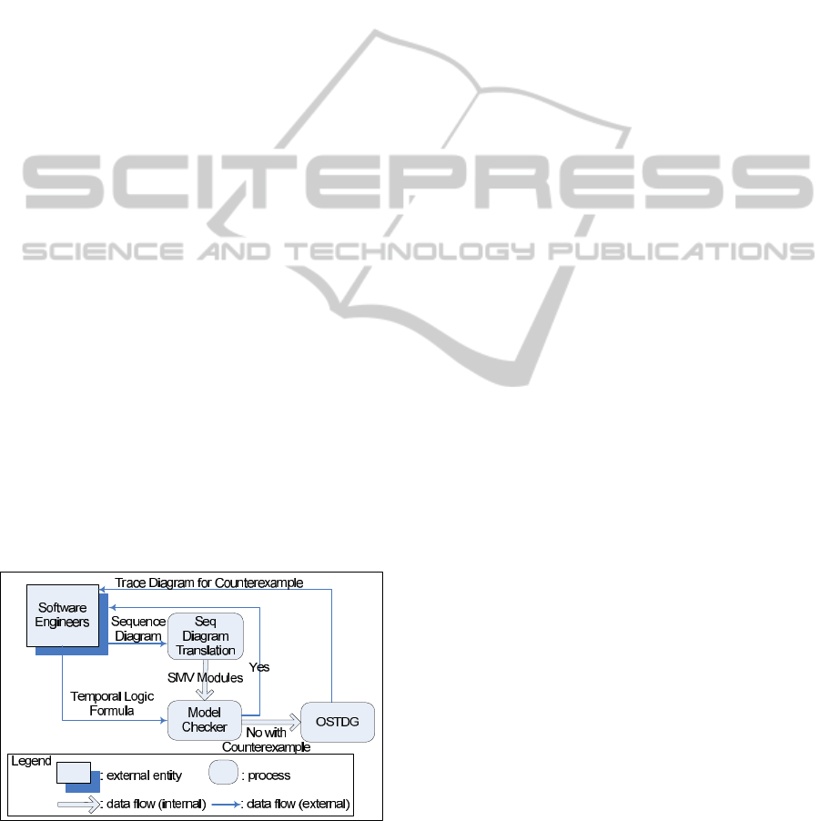
As a proof-of-concept,we have developeda tool suite,
implementing the techniques described in this paper.
Figure 5 is a data flow diagram, illustrating the archi-
tecture of our tool suite.
Figure 5: Architecture of tool suite.
The software engineer uses MagicDraw to create
a Sequence Diagram, which can be converted to a tex-
tual representation in terms of XML using our Mag-
icDraw plugin. The Sequence Diagram Translation
tool takes the XML representation as input, parses it
into a syntax tree, and transforms it into a NuSMV
model. NuSMV model checker takes as input the
generated NuSMV model and a temporal logic for-
mula that is specified by the software engineer. If
there are no property violations, the software engi-
neer receives a positive response. If property vi-
olations exist, NuSMV generates a counterexample
which is then passed to our Occurrence Specification
Trace Diagram Generator (OSTDG) tool. The output
from the OSTDG is an easy-to-read Sequence Dia-
gram visualization of the counterexample to help the
software engineer locate the property violation faster.
Thus, the software engineer may transparently verify
a Sequence Diagrams using NuSMV, staying solely
within the notation realm of Sequence Diagrams.
We evaluate our technique with a case study of
ISIS (Insurance Services Information System), a web
application currently used by the specialty insurance
industry. Our evaluation uses two Sequence Diagram
examples from the design documentation of ISIS.
We check the example on a Linux machine with a
3.00GHz, 8 cores CPU and 32GB of RAM. One ex-
ample executed in 19 minutes 49 seconds with 3,825
reachable states out of total 3.71e+012 states, while
the other example executed in 18 minutes 14 sec-
onds with 192 reachable states out of total 4.95e+012
states. Please refer to (Shen et al., 2011) for more
details of the case study and our tool suite.
6 RELATED WORK
Verification of scenario-based notation is well-
accepted as an important and challenging problem.
To the best of our knowledge, our technique is the
first to support all CFs and the nested CFs. Lima et
al. provide a tool to translate UML 2 Sequence Di-
agrams into PROMELA-based models and verify us-
ing SPIN, with counterexample visualizations (Lima
et al., 2009). Their translation does not support
Critical Region, Strict Sequencing, Negative, Asser-
tion, Consider, Ignore, synchronous Messages and
Interaction Constraint. Van Amstel et al. present
four complementary approaches for analyzing UML
1.5 Sequence Diagrams, which do not support CFs
(Van Amstel et al., 2007). They model check Se-
quence Diagrams using SPIN. Alawneh et al. intro-
duce a unified paradigm to verify and validate promi-
nent UML 2 diagrams, including Sequence Diagrams,
using NuSMV (Alawneh et al., 2006). Their approach
supports Alternatives and Parallel.
To model check MSCs, Alur et al. (Alur and Yan-
ICSOFT2012-7thInternationalConferenceonSoftwareParadigmTrends
52

nakakis, 1999; Alur et al., 2005) formalize MSC us-
ing automata. They examine different cases of MSC
verification of temporal properties and present tech-
niques for iteratively specifying requirements (Alur
et al., 2003). They focus on MSC Graph, which
is an aggregation of MSCs. We extend their work
to encompass more complicated aggregations using
CFs. Peled et al. perform intensive research on the
verification of MSCs (Muscholl et al., 1998; Gunter
et al., 2001), in particular, they present an extension
of the High-Level MSC (Peled, 2000). They spec-
ify MSC properties in temporal logic and check for
safety and liveness properties. Leue et al. translate
the MSC specification, especially branching and iter-
ation of High-Level MSC, into PROMELA to verify
MSCs using the XSPIN tool (Leue and Ladkin, 1996).
As Sequence Diagrams have similar expressive fea-
tures, our technique can be extended to work with
their approach. Kugler et al. improve the technique
of smart play-out, which is used to model check LSCs
to avoid violations over computations (Kugler et al.,
2009). Walkinshaw and Bogdanov (Walkinshaw and
Bogdanov, 2008) detail an inference technique to con-
strain a finite-state model with LTL. These constraints
reduce the number of traces required as input to a
model checker for discovery of safety counter exam-
ples. Our work can automatically model check each
Sequence Diagram of a system against LTL properties
separately, which helps to alleviate the state explosion
problem.
Micskei and Waeselynck survey comprehensively
formal semantics proposed for Sequence Diagrams by
13 groups and present the different semantic options
(Micskei and Waeselynck, 2011). In these groups,
Knapp and Wuttke present an operational seman-
tics for a translation of an Interaction into automata,
which is used to model check UML state machines
with SPIN or UPPAAL (Knapp and Wuttke, 2006).
Their approach does not support all CFs and the in-
terpretation of automata restricts the specification of
Interaction Constraints. Haugen et al. present the for-
mal semantics of UML 2 Sequence Diagram through
an approach named STAIRS (Haugen et al., 2005).
STAIRS provides a trace-based representation for a
subset of CFs, focusing on the refinement for Interac-
tions. To relate state-based behaviors with scenario-
based descriptions, Bontemps et al. formally study
the problem of scenario checking, synthesis, and ver-
ification of the LSC (Bontemps et al., 2005). Their
work focuses on providing an algorithm and proving
the complexityfor each problem. Uchitel et al. (Uchi-
tel et al., 2003) synthesize a behavioral specification
in the form of a Finite Sequential Process, which can
be checked using their labeled transition system ana-
lyzer. With the semantic definition of Uchitel et al.,
Damas et al. synthesize a labeled transition system
model from both positive and negative scenarios, ex-
pressed in MSC (Damas et al., 2005).
7 CONCLUSIONS
In this paper, we present an approach to transform
Sequence Diagrams and all CFs into NuSMV mod-
els. This enables software engineers to verify if a Se-
quence Diagram satisfies desired properties and visu-
alize counterexamples as Sequence Diagrams to help
user locate violations. We supplement our technique
with a proof-of-concept tool suite and perform an
evaluation using a case study of an industry web ap-
plication. We believe our approach can be adapted to
model check MSCs and High-Level MSCs.
ACKNOWLEDGEMENTS
Jianwei Niu is supported in part by NSF award CNS-
0964710.
REFERENCES
Alawneh, L., Debbabi, M., Hassaine, F., Jarraya, Y., and
Soeanu, A. (2006). A unified approach for verifica-
tion and validation of systems and software engineer-
ing models. In ECBS 2006, pages 409–418.
Alur, R., Etessami, K., and Yannakakis, M. (2003). Infer-
ence of Message Sequence Charts. TSE, 29(7):623–
633.
Alur, R., Etessami, K., and Yannakakis, M. (2005). Real-
izability and verification of MSC graphs. Theoretical
Computer Science, 331(1):97–114.
Alur, R. and Yannakakis, M. (1999). Model checking
of Message Sequence Charts. In CONCUR, volume
1664 of LNCS, pages 114–129.
Bontemps, Y., Heymans, P., and Schobbens, P.-Y. (2005).
From Live Sequence Charts to state machines and
back: A guided tour. TSE, 31(12):999–1014.
Cimatti, A., Clarke, E., Giunchiglia, F., and Roveri, M.
(2000). NuSMV: a new symbolic model checker. Int.
Journal on Soft. Tools for Tech. Transfer, 2:410–425.
Damas, C., Lambeau, B., Dupont, P., and van Lamsweerde,
A. (2005). Generating annotated behavior models
from end-user scenarios. TSE, 31(12):1056–1073.
Eichner, C., Fleischhack, H., Meyer, R., Schrimpf, U., and
Stehno, C. (2005). Compositional semantics for UML
2.0 Sequence Diagram using Petri Nets. In Int. SDL
Forum, volume 3530 of LNCS, pages 133–148.
Gunter, E. L., Muscholl, A., and Peled, D. (2001). Compo-
sitional Message Sequence Charts. In TACAS, volume
2031 of LNCS, pages 496–511.
FormalAnalysisofSequenceDiagramwithCombinedFragments
53

Haugen, O., Husa, K. E., Runde, R. K., and Stolen, K.
(2005). STAIRS towards formal design with Sequence
Diagrams. Soft. and Sys. Modeling, 4(4):355–357.
Knapp, A. and Wuttke, J. (2006). Model checking of UML
2.0 interactions. In MODELS, volume 4364 of LNCS,
pages 42–51.
Kugler, H., Harel, D., Pnueli, A., Lu, Y., and Bontemps,
Y. (2005). Temporal logic for scenario-based spec-
ifications. In TACAS, volume 3440 of LNCS, pages
445–460.
Kugler, H., Plock, C., and Pnueli, A. (2009). Controller
synthesis from LSC requirements. In FASE, volume
5503 of LNCS, pages 79–93.
Leue, S. and Ladkin, P. B. (1996). Implementing and ver-
ifying MSC specifications using PROMELA/XSPIN.
In SPIN96, volume 32 of DIMACS, pages 65–89.
Lima, V., Talhi, C., Mouheb, D., Debbabi, M., Wang,
L., and Pourzandi, M. (2009). Formal verification
and validation of UML 2.0 Sequence Diagrams using
source and destination of messages. Electron. Notes
Theor. Comput. Sci., 254:143–160.
Micskei, Z. and Waeselynck, H. (2011). The many mean-
ings of UML 2 Sequence Diagrams: a survey. Soft-
ware and Systems Modeling, 10(4):489–514.
Muscholl, A., Peled, D., and Su, Z. (1998). Deciding prop-
erties of Message Sequence Charts. In Int. Conf. on
Foundations of Soft. Sci. and Computation Structure,
volume 1378 of LNCS, pages 226–242.
Object Management Group (2011). Unified Modelling
Language (Superstructure), v2.4.1, 2011. Internet:
www.omg.org.
Peled, D. (2000). Specification and verification of Message
Sequence Charts. In FORTE, pages 139–154.
Shen, H., Robinson, M., and Niu, J. (2011). A log-
ical framework for Sequence Diagram with Com-
bined Fragments. Technical Report CS-TR-2011-015,
UTSA.
Uchitel, S., Kramer, J., and Magge, J. (2003). Synthesis
of behavioral models from scenarios. TSE, 29(2):99–
115.
Van Amstel, M., Lange, C., and Chaudron, M. (2007). Four
automated approaches to analyze the quality of UML
Sequence Diagrams. In COMPSAC, volume 2, pages
415–424.
Walkinshaw, N. and Bogdanov, K. (2008). Inferring finite-
state models with temporal constraints. In ASE, pages
248–257.
ICSOFT2012-7thInternationalConferenceonSoftwareParadigmTrends
54
