
TRACKING INTERACTING OBJECTS IN COMPLEX SITUATIONS
BY USING CONTEXTUAL REASONING
Rosario Di Lascio
1∗
, Pasquale Foggia
2
, Alessia Saggese
2
and Mario Vento
2†
1
A.I.Tech s.r.l.
‡
, Salerno, Italy
2
Dipartimento di Ingegneria Elettronica e Ingegneria Informatica, University of Salerno, Salerno, Italy
Keywords:
Video Surveillance, Real-time Object Tracking.
Abstract:
In this paper we propose a novel real-time tracking algorithm robust with respect to several common errors
occurring in object detection systems, especially in the presence of total or partial occlusions. The algorithm
takes into account the history of each object, whereas most other methods base their decisions on only the
last few frames. More precisely, it associates each object with a state encoding the relevant information of
its past history, that enable the most appropriate way of assigning an identity to the object on the basis of its
current and past conditions. Thus, strategies that are more complex but also riskier are only applied when
the algorithm is confident that is appropriate to do so. An experimental evaluation of the algorithm has been
performed using the PETS2010 database, comparing the obtained performance with the results of the PETS
2010 contest participants.
1 INTRODUCTION
Object tracking algorithms are devoted to the task of
reconstructing the object trajectories given the evi-
dence collected from a video sequence. Although this
task is apparently simple, several problems may ham-
per its performance: problems with the detection of
the objects in each frame (objects missing or partially
detected, spurious objects, objects split in parts), oc-
clusions (a person is totally or partially covered by an
element of the scene, or by another person), noise due
to light changes or camera motion. Thus, many algo-
rithms have been proposed in the literature for facing
these problems, but none of them is both sufficiently
reliable to operate in the complexity of a real world
scenario, and sufficiently fast to work in real time.
The algorithms present in the literature can be
roughly divided into two categories. In the first one,
tracking is performed after an object detection phase:
objects are detected in each frame using either some
form of change detection (e.g. differences from a
background model) or an a priori model of the ob-
∗
This research has been partially supported by A.I.Tech
s.r.l., a spin-off company of the University of Salerno
(www.aitech-solutions.eu).
†
IAPR Fellow.
‡
A Spin-off company of the University of Salerno:
www.aitech-solutions.eu.
jects. Algorithms in this category are usually faster,
but they have to consider also the errors of the de-
tection phase, such as spurious and missing objects,
objects split into pieces, multiple objects merged into
a single detected blob). As an example, the papers
by (Seth and Jain, 1987), by (Rangarajan and Shah,
1991) and by (Intille et al., 1997) use a greedy algo-
rithm that matches each object to its nearest neighbor,
with constraints based on proximity. The first method
assumes that the number of objects is constant, so it
does not deal with object entries, exits and occlusions;
the later methods add the ability to deal with entering
or exiting objects and to recognize that an occlusion
has occurred (without restoring the object identities
after the occlusion).
The W
4
system by (Haritaoglu et al., 2000) uses
the overlap of the areas as a criterion to find a corre-
spondence between the objects at the current and at
the previous frame. When this criterion selects mul-
tiple objects, the algorithm considers split or merge
hypotheses to deal with detection errors or with oc-
clusions. After an occlusion, an appearance model of
the objects is used to reassign the original object iden-
tities. Also, when an object is seen for the first time,
the algorithm waits for a fixed number of frames be-
fore assigning it an object identifier, in order to filter
out spurious objects due to detection errors. The use
of overlap works well with high frame rates and ob-
104
Di Lascio R., Foggia P., Saggese A. and Vento M..
TRACKING INTERACTING OBJECTS IN COMPLEX SITUATIONS BY USING CONTEXTUAL REASONING.
DOI: 10.5220/0003819301040113
In Proceedings of the International Conference on Computer Vision Theory and Applications (VISAPP-2012), pages 104-113
ISBN: 978-989-8565-04-4
Copyright
c
2012 SCITEPRESS (Science and Technology Publications, Lda.)

jects that are not very fast, but might fail in other con-
ditions. The method proposed by (Chen et al., 2001)
formulates the tracking problem as a bipartite graph
matching, solving it by the Hungarian algorithm. It
recognizes an occlusion, but is able to preserve the
object identities only if the horizontal projection of
the detected blob shows a separate mode.
In the second category, detection and tracking are
performed at once, usually on the basis of an object
model that is dynamically updated during the track-
ing. These methods are computationally more expen-
sive, and often have problems with the initial defini-
tion of the object models, that in some cases has to
be provided by hand. The paper by (Comaniciu et al.,
2000) proposes the use of Mean Shift, a fast, iterative
algorithm for finding the centroid of a probability dis-
tribution, for determining the most probable position
of the tracking target. It requires a manual selection
of the objects being tracked in the initial frame, and
deals only with partial occlusions. (Tao et al., 2002)
have proposed a method based on a layered represen-
tation of the scene, that is created and updated using
a probabilistic framework. Their method is able to
deal with occlusions, but is extremely computational
expensive. The method by (Wu and Nevatia, 2005)
tracks people in a crowded environment. However it
uses an a priori model of a person, that is not extend-
able to other kind of objects. Several recent methods
(Bazzani et al., 2010) have investigated the use of Par-
ticle Filters, that are a tool based on the approximate
representation of a probability distribution using a fi-
nite set of samples, for solving the tracking problem
in a Bayesian formulation. Particle Filters look very
promising, since they make tractable a very general
and flexible framework. However, the computational
cost is still too high for real-time applications, espe-
cially with multiple occluding targets.
In this paper we propose a real-time tracking algo-
rithm belonging to the first category; it assumes that
an object detection based on background subtraction
generates its input data. The algorithm is robust with
respect to the errors generated by the object detection
(spurious or missing objects, split objects) and is able
to work with partial and total occlusions.
Most of the algorithms in the first category make
their tracking decisions by comparing the evidence at
the current frame with the objects known at the pre-
vious one; all the objects are dealt with in the same
way, ignoring their past history that can give useful
hints on how they should be tracked: for instance, for
objects stable in the scene, information such as their
appearance should be considered more reliable.
To exploit this idea, the algorithm adopts an ob-
ject model based on a set of scenarios, in order to dif-
ferently deal with objects depending on their recent
history; the scenarios are implemented by Finite State
Automata, each describing the different states of an
object and the conditions triggering the transition to
a different state. The state is used both to influence
which processing steps are performed on each object,
and to choose the most appropriate value for some of
the parameters involved in the processing.
2 THE PROPOSED METHOD
Before starting the description of the algorithm, we
need to introduce some terminology and notations.
A blob is a connected set of foreground pixels pro-
duced by a detection algorithm, which usually finds
the foreground pixels by comparing the frame with a
background model; then the foreground pixels are fil-
tered to remove noise and other artifacts (e.g. shad-
ows); finally, the foreground pixels are partitioned
into connected components, which are the blobs. The
tracking algorithm receives in input the set of blobs
detected at each frame. We assume that the detection
phase uses a dynamic background model dealing with
lighting changes; noise reduction, shadow and small
blob removal are further carried out. See details in
(Conte et al., 2010).
An object is any real-world entity the system is in-
terested in tracking. Each object has an object model,
containing such information as the object class (e.g.
a person or a vehicle), state (see subsection 2.1),
size, position, trajectory and appearance (see subsec-
tion 2.4). A group object corresponds to multiple real-
world entities tracked together; if a group is formed
during the tracking (i.e. it does not enter the scene as
a group), its object model mantains a reference to the
models of the individual objects of the group.
The task of the tracking algorithm is to associate
each blob to the right object, in such a way as to
preserve the identity of real-world objects across the
video sequence; in the process the algorithm must
also create new object models or update the existing
ones as necessary.
In real cases, the detection phase produces some
common errors:
• Spurious Blobs, i.e. blobs not corresponding
to any object; they can be caused by lighting
changes, movements of the camera or of the back-
ground, and other transient changes that the detec-
tion algorithm was not able to filter out;
• Ghost Blobs, i.e. blobs appearing where there
was an object previously considered as part of the
background, that has moved away (e.g. a parked
car that starts moving);
TRACKING INTERACTING OBJECTS IN COMPLEX SITUATIONS BY USING CONTEXTUAL REASONING
105
Object
classifier
State
manager
Association
manager
Similarity
evaluator
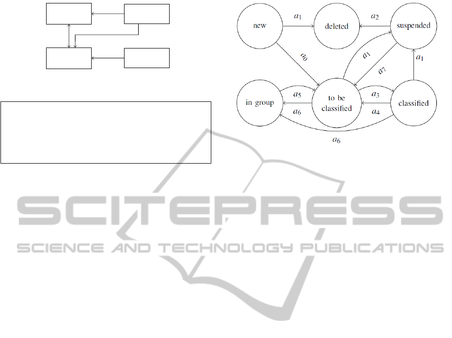
Figure 1: An overview of the tracking system.
procedure Tra c k i n g ( o b j _ models , b lobs )
Classify ( current_blob s )
S := Comput e S i m i l a r i t y ( o b j _ models ,
blobs )
Fin d A s s o c i a t i o n s ( o b j _ models , blob s , S )
UpdateModels ( o bj_mode l s , blobs )
UpdateState ( o b j _ m o d e ls )
end procedure
Figure 2: The structure of the tracking algorithm.
• Missing Blobs, i.e. undetected objects, for in-
stance as too similar to the background behind
them;
• Split Blobs, i.e. objects divided into multiple
blobs.
In addition the algorithm must also handle partial
or total occlusions, ensuring that object identities are
not lost across the occlusion.
A key idea behind the proposed algorithm is to
base the decisions regarding an object not only on its
current conditions, but also on its past history; in this
way spurious observations can be easily ignored, and
the decisions can be based on stable properties of the
object. To this aim, the object history is encoded us-
ing a state, belonging to a finite set of possible values.
The transitions between states are explicitly described
through a Finite State Automaton, and are triggered
by such events as the permanence of the object in the
scene, its disappearance, the outcome of the object
classification and the participation to an occlusion.
The object state influences decisions taken by the
association management module, which establishes
a correspondence between objects and blobs, solving
split-merge events and performing occlusion reason-
ing. Association management is mainly based on a
similarity measure between objects and blobs, con-
sidering position, size and appearance.
Figure 1 shows the modules composing the track-
ing system, and their interdependencies, while Fig-
ure 2 shows an outline of the tracking algorithm. In
the following subsections, more details are provided
for each module of the system.
2.1 Object State Management
The state manager is based on the Finite State Au-
tomaton A depicted in Figure 3, that can be formally
Figure 3: The state diagram of the object state manager.
defined as:
A =
h
S,Σ,δ,s
0
,F
i
(1)
where S = {s
0
,. .. ,s
m
} is the set of the states; Σ =
{a
0
,. .. ,a
m
} is the set of the transition conditions,
i.e. the conditions that may determine a state change;
δ : S × Σ → S is the state-transition function; s
0
∈ S is
the initial state and F ⊂ S is is the set of final states.
The proposed Finite State Automaton states and
transitions are shown in table 1. In particular, the set
of states S is shown in table 1.a; we choose s
0
as ini-
tial state, since each object enters the scene by ap-
pearing either at the edge or at a known entry region
(e.g. a doorway). Furthermore we choose s
5
as fi-
nal state, since each object necessarily has to leave
the scene. The set Σ of transition conditions and the
state-transition function δ are shown respectively in
Table 1.b and 1.c.
The meaning of the states and the conditions trig-
gering the transitions are detailed below:
• new (s
0
): the object has been just created and is
located at the borders of the frame; if it enters
completely, and so does not touch the frame bor-
ders (a
0
), it becomes to be classified; otherwise,
if it leaves the scene (a
1
), it immediately becomes
deleted;
• to be classified (s
1
): the object is completely
within the scene, but its class is not yet considered
reliable; if the classifier assigns the same class for
at least two frames (a
3
), it becomes classified; if
the association manager detects that the object has
joined a group (a
6
), it becomes in group; if the ob-
ject disappears (a
1
), it becomes suspended;
• classified (s
2
): the object is stable and reliably
classified; if the classifier assigns a different class
(a
4
), it becomes to be classified; if the association
manager detects that the object has joined a group
(a
6
), it becomes in group; if the object disappears
(a
1
), it becomes suspended;
VISAPP 2012 - International Conference on Computer Vision Theory and Applications
106

Table 1: The Finite State Automaton. (a) The set S of the
states. (b) The set Σ of the transition conditions. (c) The
state-transition function δ; for entries shown as ‘-’, the au-
tomaton remains in the current state.
(a)
Id Description
s
0
new object
s
1
to be classified object
s
2
classified object
s
3
suspended object
s
4
in group object
s
5
deleted object
(b)
Id
Description
a
0
obj enters completely within the scene
a
1
obj disappears from the scene
a
2
obj does not reappear in the scene for a time T
d
a
3
obj classification changes
a
4
obj classification remains the same for two
frames
a
5
obj leaves the group
a
6
obj occludes with one or more objects
a
7
obj reappears inside the scene
(c)
a
0
a
1
a
2
a
3
a
4
a
5
a
6
a
7
s
0
s
1
s
5
- - - - - -
s
1
- s
3
- s
2
- - s
4
-
s
2
- s
3
- - s
1
- s
4
-
s
3
- - s
5
- - - - s
1
s
4
- - - - - s
1
- -
s
5
- - - - - - - -
• in group (s
4
): the object is part of a group, and
is no more tracked individually; its object model
is preserved to be used when the object will leave
the group; if the association manager detects that
the object has left the group (a
5
), it becomes to be
classified;
• suspended (s
3
): the object is not visible, either be-
cause it is completely occluded by a background
element, or because it has left the scene; if the ob-
ject gets visible again (a
7
), it becomes to be clas-
sified; if the object remains suspended for more
than a time threshold T
d
(a
2
), it becomes deleted;
currently we use T
d
= 1 sec;
• deleted (s
5
): the object is not being tracked any-
more; its object model can be discarded.
The use of the new state allows the algorithm to
quickly discard spurious objects due to detection ar-
tifacts, since they usually do not persist long enough
to become to be classified. On the other hand, the
suspended state avoids that an object is forgotten too
soon when it momentarily disappears because of a de-
tection miss, an occlusion with the background or a
temporary exit from the scene. The in group state has
the purpose of keeping the object model even when
the object cannot be tracked individually, as long as
the algoritm knows it is included in a group. Finally,
the distinction between classified and to be classified
objects is used by the association manager when rea-
soning about split objects and group formation.
Figure 4 shows in a very simple example how the
object state management works.
2.2 Object Classification
The tracking system needs an object classifier to de-
termine if a blob corresponds to a group, an individual
object, or an object part. Currently we have applied
our system to people tracking, so we have only two
classes of individual objects: person and baggage.
For these classes, the width and the height are
a sufficiently discriminant feature vector; if the al-
gorithm should be applied to a problem with more
classes, other features could be added, for example
based on the shape of the blob. In order to obtain the
actual width and height of the object, removing the
scaling introduced by the perspective, we perform an
Inverse Perspective Mapping (IPM) based on camera
calibration data.
IPM is a geometrical transformation technique
that reconstructs the 3D position of an object from its
2D position in the image plane (Muad et al., 2004).
Once the 3D position is known, the actual size of the
object can be easily computed from its apparent size.
The classifier we have implemented is a simple
Nearest Neighbor classifier, that has a reference set of
a few objects for each class (including groups of peo-
ple). More in detail, we have a set of reference vec-
tors, R = {r
1
,. .. ,r
k
} where each r
i
a feature vector
(w
i
,h
i
) containing the width and the height of the ref-
erence object; each r
i
is associated to a known class,
denoted as class(r
i
). The blob that has to be classified
is represented by a feature vector v = (w
v
,h
v
). Then
the class is determined as follows:
j = argmin
i
kv − r
i
k (2)
class(v) = class(r
j
) (3)
where k.k denotes the Euclidean norm, and j is the
index of the reference vector that is nearest to v. The
value of kv − r
j
k can be used to check if the classifi-
cation is reliable (because the blob is very similar to
one of the reference objects) or not. If:
TRACKING INTERACTING OBJECTS IN COMPLEX SITUATIONS BY USING CONTEXTUAL REASONING
107
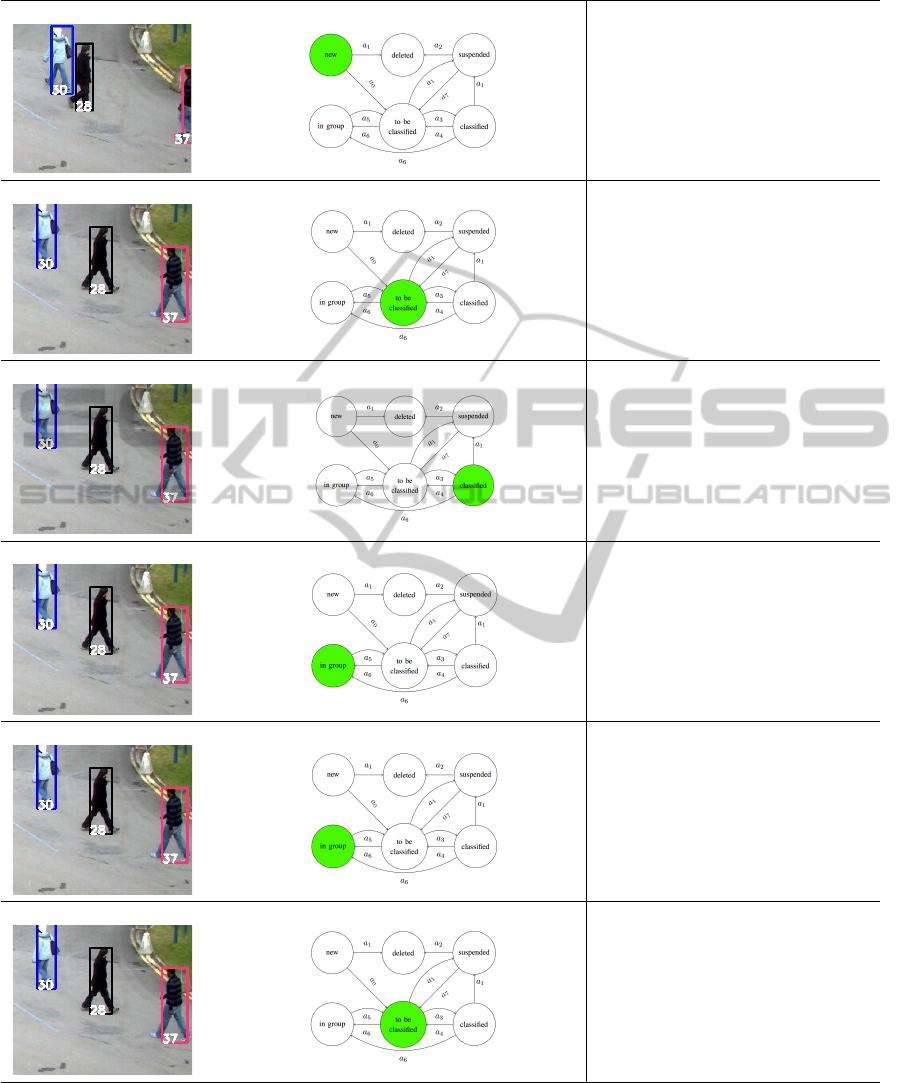
The object 37 enters the scene as a
new object.
The object 37 becomes to be classi-
fied.
When its classification as a person ob-
ject becomes reliable, the objects be-
comes classified.
After a few frames, the association
manager identifies an occlusion and
the object 37 becomes in group.
The object 37 remains inside the
group, so it does not change its state.
The association manager identifies a
split, but it does not solve it since it is
associated to a group object. In such
a way, the object exits the group and
it becomes to be classified again.
Figure 4: Each object is associated to a Finite State Automaton that aims to manage the history of an object. We focus
attention on the object identified by the number 37 since it is entering the scene.
kv − r
j
k > θ
c
(4)
where θ
c
is a classification threshold, the algorithm
assumes that the blob is likely the result of a split in
the detection phase.
At this point one can note that object evolution is
not dependent on its class (e.g. group or individual
VISAPP 2012 - International Conference on Computer Vision Theory and Applications
108

procedure TrackingAlgorithm ( obj_ m o d els , b l o b s )
As s o c i a t i o n S t a b l eObjs ( o b j _ models , b lobs )
pending_ b l o b s : = S e a rchPendingBlo b s ( b l obs )
As s o c i a t i o n I n s tableObjs ( obj_m o d e ls , p e n d i n g _ b l o b s )
un a s s o c i a t e d _ b l o b s := S e a r c h P e n d ingBlobs ( p e n d i n g _ b l o b s )
Cr e a t e O b j F r o m PendingB o x e s ( o b j _models , unassocia t e d _ b l o b s )
Up d a t e O b j e c t s S t a t e ( obj_models )
end procedure
procedure Association I n s t a b l e O b j s ( o b j _ models , b lobs )
sim_mat := O b j I n s t a b l e S imilari t y M a t r i x ( obj_m o d els , blobs)
for a ll o bj in obj_models :
( b e s t _boxes , b e s t _ o bjs ) := B e s t A s s o c i a t i o n ( sim_ma t )
end
end procedure
procedure AssociationSt a b l e O b j s ( obj_mode l s , blobs)
sim_mat := O b j S t a b l e S i m i larityMa t r i x ( o b j _models , blobs )
for a ll o bj in obj_models :
( b e s t _boxes , b e s t _ o bjs ) := B e s t A s s o c i a t i o n ( sim_ma t )
SolveMerge ( best_bo x e s , best_objs )
SolveSplit ( best_bo x e s , best_objs )
end
end procedure
Figure 5: The structure of the algorithm for stable and in-
stable objects associations.
object), but only on its actual state. As a matter of
fact, only object information is related to object class,
while object state only determines the reliability of
such information. In particular, for individual objects
we have information about appearance and shape: we
consider the area and the perimeter of an object, its
color histograms and its real dimensions, that is width
and height, both obtained using an Inverse Perspective
Mapping. Moreover we have information about the
observed and predicted position of the object centroid.
The predicted position is obtained using an extended
2D Position-Velocity (PV) Kalman Filter, whose state
vector is:
ξ =
x
c
,y
c
,w,h, ˙x
c
, ˙y
c
, ˙w,
˙
h
(5)
where (x
c
,y
c
) is the centroid of the object, w and h
are the width and the height of the object minimum
bounding box in pixels, ( ˙x
c
, ˙y
c
) and ( ˙w,
˙
h) are re-
spectively the velocity of the object centroid and the
derivative of the minimum bounding box size. It is
worth noting that such a PV Kalman Filter is very ef-
fective when the object motion is linear and the noise
has a Gaussian distribution.
Group objects contain also information about oc-
cluded objects. In this way the system can continue to
track the in group objects when they leave the group.
2.3 Association Management
The task of the association manager is to establish a
correspondence between the objects and the blobs de-
tected at the current frame. This correspondence can
be represented as a matrix T = {t
i j
} defined as:
t
i j
=
0 if obj. o
i
is not associated to blob b
j
1 if o
i
is associated to b
j
(6)
In order to perform this task, the association man-
ager may introduce new object models, and it may
request an update of the existing ones.
In simple cases, there is a one-to-one correspon-
dence between an object and a blob; in such cases, at
most one element has the value 1 in each row and in
each column of T :
∑
i
t
i j
≤ 1 ∀i;
∑
j
t
i j
≤ 1 ∀ j (7)
However, the association manager has to consider
more complex associations (one-to-many, many-to-
one, and even many-to-many) in order to deal with
occlusions and with split blobs.
The algorithm operates in two distinct phases, as
shown in Figure 5: in the first one it finds the cor-
respondence for stable objects (i.e. objects in the to
be classified or classified state); in the second phase
it tries to assign the remaining blobs to objects in the
new state, possibly creating such objects if necessary.
The motivation for this distinction is that split-merge
and occlusion reasoning is only performed for stable
objects, since for new objects the system would not
have enough information to do it in a reliable way.
The algorithm for the association of stable objects
is shown in Figure 5. It is a greedy algorithm, based
on the use of a similarity matrix. Rows and columns
of the similarity matrix are respectively used to repre-
sent the objects and the blobs. In this way each ele-
ment s
i j
of the matrix represents a similarity measure
between the blob b
j
and the object o
i
. The construc-
tion of the similarity matrix and of the similarity index
is described in detail in subsection 2.4.
The algorithm starts by choosing the maximum
element of the matrix; if its value is above a given
threshold τ, the algorithm records the corresponding
association:
(k, l) = argmax
i j
s
i j
(8)
t
k,l
= 1 if s
kl
> τ (9)
where k and l represent the indices of the maximum
element of the similarity matrix.
Then the algorithm checks if the blob b
l
of this
association has other objects that are close to it and are
not similar enough to different blobs, as an evidence
that an occlusion is starting, or that a detached object
part (or a baggage) is becoming attached to the object;
this condition can be formulated as:
∃o
m
6= o
k
: s
ml
> τ ∧ s
ml
= max
j
s
m j
(10)
The association manager uses the current state and the
output of the classifier to discriminate between the
TRACKING INTERACTING OBJECTS IN COMPLEX SITUATIONS BY USING CONTEXTUAL REASONING
109

two kinds of event, and in the first case it creates a
group object and links it with the individual objects
forming the occlusion.
At this point the algorithm verifies if the object
of the selected association o
k
has other blobs that are
close to it and are not similar enough to different ob-
jects; this may be caused by either the end of an oc-
clusion, or by a split blob; more formally:
∃b
n
6= b
l
: s
kn
> τ ∧ s
kn
= max
i
s
in
(11)
Again, the association manager uses the current state
and the classifier outputs to recognize the correct
event; in the case of an ending occlusion, the algo-
rithm uses the individual object models linked to the
group object to reassign the correct identity to the ob-
jects leaving the group, changing their state from in
group to to be classified.
Finally, the algorithm removes from the similarity
matrix all the rows and columns corresponding to ob-
jects and blobs it has used, and repeats the choice of
the maximum element in the matrix. If no element is
above the threshold τ, all the remaining unassigned
objects are put in the suspended state and the first
phase terminates.
The second phase is shown in Figure 5. It fol-
lows a similar scheme, except that it considers only
the objects in the new state, and does not perform the
checks for merges, splits, starting and ending occlu-
sions. Moreover, the similarity matrix is built using
less features than in the first phase since we have ex-
perimentally verified that only the position informa-
tion (see section 2.4) is sufficiently reliable for such
objects. At the end of this phase, any remaining unas-
signed blobs are used to create new object models,
initialized to the new state.
2.4 Similarity Evaluation
As already mentioned, the similarity matrix is used to
match one or more blobs with one or more objects. In
order to measure the similarity between an object o
i
and a blob b
j
, the tracking system uses an index based
on three kinds of information: the position, the shape
and the appearance:
s
i j
=
s
α
p
· (s
p
i j
)
2
+ α
s
· (s
s
i j
)
2
+ α
a
· (s
a
i j
)
2
α
p
+ α
s
+ α
a
(12)
As described below, s
i j
values identify similarity
metrics and α values are weights chosen according to
the state of the object and the association management
phase. In particular:
• s
p
i j
is the position similarity index, that is the dis-
tance between the estimated centroid of an object
o
i
and the centroid of a blob b
j
;
• s
s
i j
is the shape similarity index between an object
o
i
and a blob b
j
;
• s
a
i j
is the appearance similarity index between an
object o
i
and a blob b
j
, based on color histograms;
• α
p
, α
s
and α
a
are the weights of position, shape
and appearance similarity index respectively;
All α values have been chosen by experimentation
over a training set. Namely, in the first phase, selected
values for objects in the to be classified and classified
state are α
p
= α
s
= α
a
= 1 while for objects in the in
group state selected values are α
s
= α
a
= 1; α
p
= 0
since in this context shape and appearance similarity
perform better than position one. Finally, in the sec-
ond phase that evaluates new objects, we choose to
consider the only reliable feature, that is the position.
Thus selected α values are α
s
= α
a
= 0; α
p
= 1.
For the position, as we have already seen, the sys-
tem uses a Kalman filter, based on a uniform velocity
model, to predict the coordinates of the object cen-
troid at the current frame. The predicted coordinates
are compared with the center of the blob, using Eu-
clidean distance, obtaining for each object o
i
and each
blob b
j
the distance d
i j
. The position similarity index
is then computed as:
s
p
i j
= 1 − d
i j
/d
max
(13)
where d
max
is a normalization factor depending on the
maximum velocity of objects representing the maxi-
mum displacement of an object between two frames.
For characterizing the shape similarity, the system
uses the real height and the area of the blob and of the
object model; in particular if we denote as ∆h
i j
the
relative height difference between o
i
and b
j
, and as
∆A
i j
the relative area difference, the considered shape
similarity index is:
s
s
i j
= 1 −
r
(∆A
i j
)
2
+ (∆h
i j
)
2
2
(14)
Finally, as a representation of the appearance we
have used the color histograms computed separately
for the upper half and for the lower half of the ob-
ject or blob (Image Partitioning). We have experi-
mented with several criteria for comparing the his-
tograms, and we have found that the most effective
value is the χ
2
distance:
q
i j
=
1
M
∑
k
h
o
i
(k) − h
b
j
(k)
2
h
o
i
(k) + h
b
j
(k)
(15)
where index k iterates over the bins of the histogram,
h
o
i
is the histogram of object o
i
, h
b
j
is the histogram of
blob b
j
, and M is the number of bins. The appearance
similarity index is:
s
a
i j
= 1 −
s
1 − q
up
i j
2
+
1 − q
low
i j
2
2
. (16)
VISAPP 2012 - International Conference on Computer Vision Theory and Applications
110
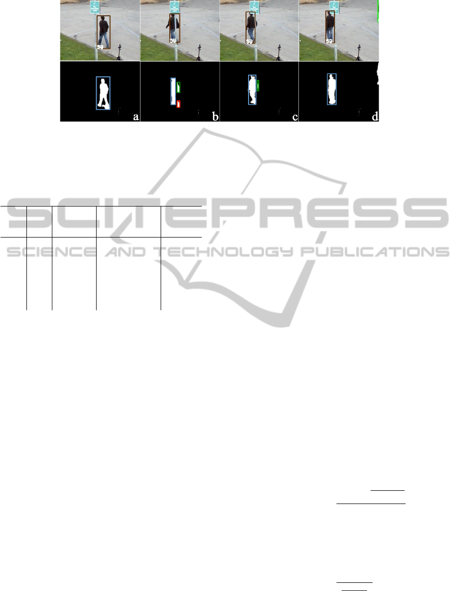
Figure 6: The output of the method on a PETS2010 sequence containing a split, caused by the presence of a pole in the scene.
The first row shows the result of the method, while the second one the list of the blobs, which is the input of the tracking
phase. Note that the object identified by 59 is correctly tracked, not withstanding the split in frames (b) and (c).
Table 2: The real number of occurrences of the objects in
the scenes and the number of id switches.
View Objs
Objs
Occur-
rences
Correctly
Identified
Objs
Id
Switch
1 22
4840 4592 (95%) 92 (3%)
3 21
6377 4925 (77%) 294 (5%)
4 22
6076 4440 (73%) 158 (3%)
5 28
2722 2344 (86%) 76 (3%)
6 32
3141 2621 (84%) 156 (5%)
7 29
4578 3225 (70%) 147 (3%)
8 26
4310 3406 (79%) 107 (2%)
where q
up
i j
is the value of q
i j
computed using only the
upper half of the object/blob, and q
low
i j
is the value
computed using only the lower half.
3 EXPERIMENTAL VALIDATION
In order to assess the performance of the method
with respect to the state of the art, we have used the
publicly available PETS 2010 database (13th IEEE
Int. Workshop on Performance Evaluation of Track-
ing and Surveillance, 2010), currently used by many
research papers. It is made of seven videos captured
in a real-world environment, containing several oc-
clusions between a person and an object, two per-
sons or among several persons. We have computed
in each view the maximum velocity of the objects,
from which we have derived the optimal values of the
d
max
parameter of equation 13, that are d
max
= 100 for
views 1, 3 and 4 and d
max
= 150 for view 5, 6, 7 and
8.
Figures 6 and 7 show two excerpts, respectively
containing a split pattern and a complex occlusion
pattern among three persons; as it can be seen, in both
the situations the system preserves the object identi-
ties across the occlusion and the split. A quantita-
tive evaluation has been carried out using the perfor-
mance indexing proposed in the PETS 2010 contest
(Ellis and Ferryman, 2010). In particular, we have
used the following indices: the Average Tracking Ac-
curacy (ATA), the Multiple Object Tracking Accuracy
(MOTA) and the Multiple Object Tracking Precision
(MOTP). In the following we introduce some nota-
tions useful to formally define them.
Let G
(t)
i
and D
(t)
i
be the ith ground truth object
and the detected one in frame t; N
(t)
G
and N
(t)
D
denote
the number of ground truth objects and detected ones
in frame t, respectively, while N
G
and N
D
denote the
number of ground truth objects and unique detected
ones in the given sequences. N
f rames
is the number
of frames in the sequences. Finally, N
mapped
refers to
the mapped system output objects over an entire refer-
ence track, taking into account splits and merges and
and N
(t)
mapped
refers to the number of mapped objects
in the tth frame.
ATA is a spatiotemporal measure that penalizes
fragmentations in spatiotemporal dimensions while
accounting for the number of objects detected and
tracked, missed objects, and false positives. ATA is
defined in terms of Sequence Track Detection Accu-
racy STDA:
ST DA =
N
mapped
∑
i=1
∑
N
f rames
t=1
|G
(t)
i
∩D
(t)
i
|
|G
(t)
i
∪D
(t)
i
|
N
G
i
∪D
i
6=0
. (17)
La latter measures the overlap in the spatiotempo-
ral dimension of the detected object over the ground
truth, taking a maximum value of N
G
. The ATA is
defined as the STDA per object:
ATA =
ST DA
N
G
+N
D
2
. (18)
As already mentioned, MOTA is an accuracy score
computing the number of missed detects, false pos-
itives and switches in the system output track for a
TRACKING INTERACTING OBJECTS IN COMPLEX SITUATIONS BY USING CONTEXTUAL REASONING
111
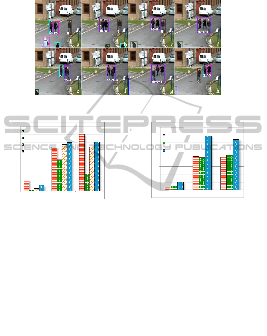
Figure 7: The output of the proposed method on a PETS2010 sequence containing an occlusion. Note how the object 9 is
correctly tracked inside the different groups although it quickly changes its direction in the frame (c).
0
0,1
0,2
0,3
0,4
0,5
0,6
0,7
0,8
ATA MOTP MOTA
BerclazLP
Arsic
Conte
Our Method
Figure 8: Performance of the method compared with the
PETS 2010 contest participants on all the views.
given reference ground truth track. It is defined as:
MOTA = 1 −
∑
N
f rames
t=1
c
m
· m
t
+ c
f
· f p
t
+ c
s
· is
t
∑
N
f rames
t=1
N
(t)
G
,
(19)
where m
t
is the number of misses, f p
t
is the num-
ber of false positives, and is
t
is the number of ID
mismatches in frame t considering the mapping in
frame (t − 1); c values are weights chosen as follow:
c
m
= c
f
= 1; c
s
= log
10
.
Finally, MOTP is a precision score calculating the
spatiotemporal overlap between the reference tracks
and the system output tracks:
MOTP =
∑
N
mapped
i=1
∑
N
(t)
f rames
t=1
|G
(t)
i
∩D
(t)
i
|
|G
(t)
i
∪D
(t)
i
|
∑
N
f rames
t=1
N
(t)
mapped
. (20)
Before analysing the performance of the method,
let us point out some properties of the considered
views. The first view presents interactions among two
0
0,1
0,2
0,3
0,4
0,5
0,6
0,7
0,8
ATA MOTP MOTA
Alahi Ogreedy
Alahi Olasso
Our Method
Figure 9: Performance of the method compared with the
PETS 2010 contest participants on views 1, 5, 6 and 8.
or three objects; the only difficulty is due to the pres-
ence of the pole and of the sign hanged on it, which
causes a lot of splits. Note that the proposed method
proves to be particularly robust with respect to the
split situations on this view.
Views 3 and 4 are the most complex; in particular,
view 3 is characterized by the presence of a large tree
(about one-third of the scene), occluding a lot of indi-
vidual or group objects. The situation is further com-
plicated by the complexity of interactions among the
objects, which involves in the average 2 − 5 objects
for view 3 and 2 − 6 for view 4. Another problem in
view 4 is the presence of a white-orange ribbon, con-
tinuously moving because of the wind. Such situation
causes a lot of problems also in the detection phase.
The problem of the moving ribbon is also present
in views 5, 6, 7 and 8, even if it is less visible. We
can note that the performance obtained in views 6 and
7 is generally lower than that obtained on other se-
quences; this is related to more complex interactions
between the tracked objects, having a very high num-
VISAPP 2012 - International Conference on Computer Vision Theory and Applications
112

ber of occlusions associated to objects that are enter-
ing the scene (unstable objects).
It is worth noting that the method, during an oc-
clusion, does not attempt to find the exact position
of an object inside a group; it continues to track the
group as a whole, using the Kalman filter for obtain-
ing a prevision of the position of each object inside the
group itself; this choice obviously causes a degrada-
tion of the performance if it is measured using indices
defined assuming that objects are always tracked in-
dividually.
Figures 8 and 9 show the performance of the
method, compared with the participants on the PETS
2010 competition. It is worth noting that the results
presented to the PETS 2010 by other competitors in
some cases only refer to a subset of the views (Views
1, 5, 6 and 8). For such reason, in order to have a
proper comparison with these methods, we present
the experimental results computed both over all the
views and over the same subset of views as these
methods. In particular, the results in Figures 8 refer
to all the views of the database, while Figure 9 only
refers to views 1, 5, 6 and 8. We can note that in the
first comparison our method outperforms the others
on the precision index (MOTP), while in the second
one it clearly outperforms all the other participants of
the context on these views on all the indices. Table 2
presents for each view a detail of the performance of
our algorithm. As for the computational cost, the sys-
tem runs at 16 milliseconds per frame on 4CIF im-
ages, using an Intel Xeon processor at 3.0GHz.
4 CONCLUSIONS
In this paper we have presented a real-time tracking
algorithm able to overcome many of the problems of
the object detection phase, as well as total or partial
occlusions. It has been experimentally validated on
a public database, showing a significant performance
improvement over the participants to an international
competition.
REFERENCES
13th IEEE Int. Workshop on Performance
Evaluation of Tracking and Surveillance
(2010). The PETS 2010 benchmark data.
http://www.cvg.rdg.ac.uk/PETS2010/.
Bazzani, L., Cristani, M., and Murino, V. (2010). Collab-
orative particle filters for group tracking. In IEEE
Int. Conf. on Image Processing, pages 837–840.
Chen, H.-T., Lin, H.-H., and Liu, T.-L. (2001). Multi-
object tracking using dynamical graph matching. In
Proc. of the IEEE Conf. on Computer Vision and Pat-
tern Recognition, volume 2, pages 210–217.
Comaniciu, D., Ramesh, V., and Meer, P. (2000). Real-
time tracking of non-rigid objects using mean shift.
In Proc. of the IEEE Conf. on Computer Vision and
Pattern Recognition, volume 2, pages 142–149.
Conte, D., Foggia, P., Percannella, G., Tufano, F., and
Vento, M. (2010). An experimental evaluation of
foreground detection algorithms in real scenes. In
EURASIP Journal on Advances in Signal Processing,
volume 11.
Ellis, A. and Ferryman, J. (2010). PETS2010 and
PETS2009 evaluation of results using individual
ground truthed single views. In IEEE Int. Conf. on
Advanced Video and Signal Based Surveillance, pages
135–142.
Haritaoglu, I., Harwood, D., and David, L. S. (2000). W4:
Real-time surveillance of people and their activities.
IEEE Trans. on Pattern Analysis and Machine Intelli-
gence, 22(8):809–830.
Intille, S. S., Davis, J. W., and Bobick, A. F. (1997). Real-
time closed-world tracking. In IEEE Conf. on Com-
puter Vision and Pattern Recognition, pages 697–703.
Muad, A., Hussain, A., Samad, S., Mustaffa, M., and Ma-
jlis, B. (2004). Implementation of inverse perspective
mapping algorithm for the development of an auto-
matic lane tracking system. In TENCON 2004. 2004
IEEE Region 10 Conference, volume A, pages 207 –
210 Vol. 1.
Rangarajan, K. and Shah, M. (1991). Establishing mo-
tion correspondence. CVGIP: Image Understanding,
54(1):56 – 73.
Seth, I. and Jain, R. (1987). Finding trajectories of fea-
ture points in a monocular image sequence. IEEE
Trans. on Pattern Analysis and Machine Intelligence,
9(1):56–73.
Tao, H., Sawhney, H. S., and Kumar, R. (2002). Object
tracking with bayesian estimation of dynamic layer
representations. IEEE Trans. on Pattern Analysis and
Machine Intelligence, 24(1):75–89.
Wu, B. and Nevatia, R. (2005). Detection of multiple, par-
tially occluded humans in a single image by bayesian
combination of edgelet part detectors. In Tenth IEEE
Int. Conf. on Computer Vision, volume 1, pages 90–
97.
TRACKING INTERACTING OBJECTS IN COMPLEX SITUATIONS BY USING CONTEXTUAL REASONING
113
