
SEMANTIC MANAGEMENT OF INTELLIGENT MULTI-AGENTS
SYSTEMS IN A 3D ENVIRONMENT
Florian B
´
eh
´
e
1,2
, Christophe Nicolle
1
, St
´
ephane Galland
2
and Abder Koukam
2
1
Laboratoire Electronique, Informatique et Image - UMR CNRS 5258, IUT Dijon Auxerre, Universit
´
e de Bourgogne
BP 17867 21078 Dijon Cedex, France
2
Laboratoire Syst
`
emes et Transports, Universit
´
e de Technologie de Belfort-Montb
´
eliard, 90010 Belfort Cedex, France
Keywords:
Ontology, Intelligent multi-agent systems, Knowledge acquisition, Industry foundation classes.
Abstract:
This paper presents a new approach combining the 3D elements composing the environment of mobile agents
with semantic descriptors from Building Information Models. Our proposal is based on the IFC standard,
which is used in the field of Civil Engineering to build digital models of buildings during the design phase.
The semantic of IFC objects composing the 3D environment is used to select and set up 3D objects and
elements of simulation scenarios. The result of this process dynamically generates the input files for the JaSIM
environment that performs the simulation. These files deserve the representation of the virtual environment in
which the simulation is running. It is represented by two separate files: a COLLADA file for the geometry
and a RDF file for its semantics. Both files are generated according to the data extracted and selected from an
IFC file by the user.
1 INTRODUCTION
The construction of a building is organized into sev-
eral steps, from conception to completion. This col-
laborative work requires the involvement of multiple
stakeholders throughout the life cycle of the building.
Many standards have been defined in each trade in-
volved in this life cycle. However, this cooperation
still faces problems of heterogeneity (Vanlande et al.,
2008). To resolve the first levels of heterogeneity
(syntactic, structural and schematic) a standard called
Industry Foundation Classes (IFC) was imposed in
the world of civil engineering. The IFC standard was
created in the late 90s by the International Alliance
for Interoperability (now called buildingSMART). Its
goal is to build a common data model for all the ac-
tors in the building industry to resolve problems of
heterogeneity. The IFC standard is the kernel of the
new generation of BIM. Several versions of the IFC
have been published, because of the gradual increase
of the covered area. The heart of the model was stabi-
lized in 2005 and received the ISO certification as ISO
/ PAS 16739: 2005. The current release is 2x3TC1.
It is an ASCII file containing all the elements of the
described building and may be displayed in 3D. The
next version of the IFC, named IFC4, should see its fi-
nal version published at the same time as the interna-
tional standard ISO/IS16739
1
. IFCs enable the ex-
change of data, either in the form of geometries, but
as objects and their structures (walls, doors, windows,
stairs ...). IFC files contain a description of all objects
in the buildings and their links. The format also de-
scribes more abstract concepts such as schedules, ac-
tivities, places, organizations, construction cost, etc.
Gradually, publishers of CAD software and gener-
ally all software for civil engineering (structural anal-
ysis, air conditioning ...) develop translation func-
tions of their proprietary language to the IFC standard
(Cruz and Nicolle, 2008). Beyond a simple format for
interoperability, the IFCs, which describe both the ge-
ometric representation of objects in the buildings and
their semantics can be used to manage ontology ag-
gregating all knowledge of the buildings (contractual
document, pictures, dashboards...) (Cruz and Nicolle,
2005; Vanlande et al., 2003; Cruz and Nicolle, 2010).
This semantic translation of building information can
also be used to achieve new goals in qualifying the use
of the building from the design phase. The combined
use of 3D and semantics of IFC is perfectly suited to
the construction of an intelligent multi-agent system
to simulate the behavior of mobile entities in a 3D en-
vironment. This system helps to qualify the use of the
1
The name of the ISO standard for IFC4
91
Béhé F., Nicolle C., Galland S. and Koukam A..
SEMANTIC MANAGEMENT OF INTELLIGENT MULTI-AGENTS SYSTEMS IN A 3D ENVIRONMENT.
DOI: 10.5220/0003664300910098
In Proceedings of the International Conference on Knowledge Engineering and Ontology Development (KEOD-2011), pages 91-98
ISBN: 978-989-8425-80-5
Copyright
c
2011 SCITEPRESS (Science and Technology Publications, Lda.)

environment and especially to improve, using seman-
tics, the existing processes in the field of multi-agent
located in a 3D environment. This paper discusses
an ongoing research on the design of a multi-agent
system based on a semantic indexing of IFC objects.
This indexing process allows to build dynamically an
informed environment (composed of 3D objects se-
mantically indexed) and intelligent agents that can re-
act to the environment according to a context of use.
The new section presents the existing works on us-
ing semantics in Multi-Agents Systems. Section 3
overviews the proposed the principle of the envi-
ronment representation and the architecture of the
semantic-based environment generation tool. Finally,
Section 4 concludes this work and draws several per-
spectives.
2 BACKGROUND
This paper is located in the domain of the simulation
of buildings flows with situated multi-agent systems.
A multi-agent system (MAS) is a system composed of
multiple interacting intelligent software agents (Fer-
ber, 1995). Multi-agent systems can be used to solve
problems that are difficult or impossible for an in-
dividual agent or a monolithic system to solve. A
multi-agent system is situated when the agents are
immersed inside an environment. In the domain of
buildings simulation, an agent is assumed to be a
pedestrian, or any object that owns an autonomous
decision-making process. The environment is then
everything that is not an agent in the buildings.
Three different points of view may be adopted
to study the notion of environment in situated MAS
(Weyns et al., 2007): (i) the part of the system
which is outside the community of the agents; (ii) the
medium for coordination among these agents; or
(iii) the running infrastructure or platform. Weyns
et al. distinguish between the physical environment
and the communication environment (Weyns et al.,
2006). The physical environment provides the laws,
rules, constraints and policies that govern and support
the physical existence of agents and the other entities.
In the rest of this paper, only this aspect of the envi-
ronment is taken.
Several problems may be solved to properly im-
plement an environment: its topological and geomet-
rical description, its dynamics, and the meanings of
each object and zones in the environment. The two
first points are addressed by the JaSIM environment
model (Galland et al., 2009). The last point is ad-
dressed by both the integration of semantics in the en-
vironment and modification of the agent’s algorithms
that uses them. Most of the approaches found in the
literature are based on the tagging process of the en-
vironment.
• Tagging is Often used as a Kind of Semantic.
The concept of tagging consists in placing some
tags in the environment to inform agents on var-
ious subjects. Basically, tags are considered as
objects placed in the scene, but they do not have
a physical presence. They are invisible for the
viewer of the scene and are only being seen by the
agents. Our proposal includes to describe through
tags the usage of some places, i.e. where an agent
can sit, pass through, etc. Lugrin and Cavazza
(Lugrin and Cavazza, 2007) places various tags
on a single object. These tags are linked between
and can also represent information. For example,
a glass will be represented by a geometry and two
tags. The geometry will deserve its representa-
tion and also dimensions in the simulated world.
The first tag is a “containing” tag that will notify
agents that the object on which this tag is applied
can contain some things. The second tag is an
“opening” tag that will represent the fact that the
object is opened, and then the inside of this object
is accessible. These two tags are linked together
to represent the fact that if an agent interact with
the “opening” tag, that will affect the state of the
“containing” one. Finally, a last link is made be-
tween the “opening” tag and the environment to
represent the fact that the opening is accessible di-
rectly from the environment space.
In this proposal, the evolution of an object is done
by modifying the tags and links of this object. For
example, if the glass is clogged, the link between
the opening tag and the environment is deleted
and this tag is no more accessible from the en-
vironment.
Yersin et al. (Yersin et al., 2005) propose to imple-
ment a navigation graph with the help of tagging.
This approach consists in covering the maximum
amount of navigable areas with a minimum num-
ber of discs covering these areas and not overlap-
ping any obstacle. These discs overlap themselves
and form a navigation — center to center — graph
in which agents are sure to do not collide with
any obstacle. Moreover, these discs have labels
to define the name of the zone in which they are
located. These labels are very useful to select a
target without knowing its position in the environ-
ment.
• Using Roles in Addition of Tagging. In a sim-
ilar way, De Paiva et al. (De Paiva et al., 2005)
propose to put labels on areas in order to asso-
ciate a name with a position. But in opposite to
KEOD 2011 - International Conference on Knowledge Engineering and Ontology Development
92

the previous works, the agents can only go to a lo-
cation according to its name and not its position.
In addition, the authors propose to assign roles to
the agents and make them evolving in the envi-
ronment according to their roles and the current
simulation time. For example, a kid is at “school”
at 11am and a working adult is at “office” at the
same time. This approach is useful to only have
agents that are in a given place, i.e. an agent which
is supposed to be a student is not in the headquar-
ters of a company, except if his behavior needs it.
• Misc. Gutierrez et al. (Gutierrez et al., 2005) pro-
pose to use semantic to describe the interactions
among the agents and the environment objects to
use them with various physical devices (mouse,
keyboard, etc.). This approach can be extended to
describe, for example, the interactions of agents
representing disabled people.
In this paper, the definition of the environment
is extended with semantics and agent behaviors are
adapted to use these semantic informations. Indeed
with semantics, the result of the simulation of the in-
dividuals is not only based on the geometric features
but also on the information embedded in the spatial
and temporal contexts of the simulation.
3 PROPOSAL
This section presents the principle and architecture of
our proposal, which generates the four JaSIM input
files from an BIM/IFC file.
3.1 Previous JaSIM State
Simulation of autonomous entities in a complex urban
system requires dedicated software models. JaSIM
platform (Galland et al., 2009) integrates components
which are required to simulation complex environ-
ments in 1D, 2D and 3D (in particular, particular it is
used for simulation in virtual reality). This platform
integrates several models to reproduce human visual
perception in a virtual environment and endogenous
behavior of this environment. Thus simulated entities
can use the JaSIM platform to perceive and act in a
situated system.
To run a simulation, JaSIM requires two kinds of
input files. A third kind of file may be needed if the
simulation has to be displayed.
• SFG File: A SFG file is a XML-based file that
can be seen as the scenario description of the sim-
ulation. It will contain various informations about
the simulation and the environment: definitions of
the places, spawning areas for the agents, goals,
way points, stochastic generation laws, etc. An
example of SFG configuration file can be seen in
Listing 1.
<? xml v e r s i o n = ” 1.0 ” e n c oding=”UTF−8” ?>
<!DOCTYPE s i m u l a t i o n PUBLIC ” −// s e t . utbm . f r / / DTD
J a S i m C o n f i g u r a t i o n F i l e 3 d v7 . 0 / / EN” ” / f r / utbm / s e t
/ j a s i m / c o n t r o l l e r / c o n f i g / j a s i m −c o n f i g −3d − 7 . 0 . d t d
”>
<s i m u l a t i o n i d = ” 68552 a ab−e71a −44d4−b321 −9d 9 e c 9b937 f a ”
name=”DEMO−SIMULATION”
d a t e = ” 2009−12−23”
a u t h o r s = ”GALLAND S t e phane ”
v e r s i o n =” 0 . 1 ”
d t d v e r s i o n = ” 7 . 0 ”
d e s c r i p t i o n =” S i m u l a t i o n o f P e d e s t r i a n s ”>
<t i m e t y p e =” s t e p ” u n i t = ” m i l l i s e c o n d ” t i m e S t e p = ” 500
” />
<e n v i r o n m e n t d i m e nsion=” 3 d ”>
<p l a c e s>
<p l a c e i d =” e 19f d4d 1 −73f0 −4283−82b0−0d950d53bb 62
” name= ” Mai n Hal l ”>
<g roun d E n viron m e n t i d =” f 39 772 58 −9d02 −4b71
−8201− b96 d7e 684 e62 ” t y p e =” c o n s t a n t ”>
<i ndoo r G roun d minx=” −128.66 ” miny= ” −118.23 ”
maxx= ” 1 2 8 .66 ” maxy=” 1 1 8 . 2 3 ” z=” 0 ”
s e m a n t i c = ” ” />
</ g r o u ndEnv i r o nmen t>
</ p l a c e>
</ p l a c e s>
<p o r t a l s>
</ p o r t a l s>
</ e n v i r o n m e n t>
<s pawn e r s>
<spa w ner t y p e = ” a r e a ”
i d = ” 7 a 6d7 aca −4621−4 e f a −97b3−a 5 c 0 8 4 a f f 2 0 f ”
name=”SPAWNER 1 ”
x= ” −8.5209 ”
y= ” −91.81 71 ”
z=” 0 ”
w idth=” 10 ” h e i g h t =” 10” s t a r t A n g l e = ” 0 ” end Ang le
=” 6 . 283 1 8 530 8 ”
p l a c e = ” e 19f d4d 1 −73f 0 −4283−82b0−0d950d 53 bb 62 ”>
<e n t i t y b u d g e t =” 20 ” agen t T ype=” f r . utbm . s e t .
j a s i m . demos . p e d e s t r i a n s . h o lon .
P e d e s t r i a n H o l o n ” >
<f r u s t u m s>
<f r u s t u m t y p e = ” sp h e r e ” e y e P o s i t i o n =” 1 . 8 ”
f a r D i s t a n c e = ” 10 ” />
</ f r u s t u m s>
<g e n e r a t i o n L a w c l a s s =” f r . utbm . s e t . j a s i m . spawn
. C ons tan tSp awn i ng L aw ”>
<lawParam name=” v a l u e ” v a l u e = ” 2000 ” />
</ g e n e r a t i o n L aw>
</ e n t i t y>
</ s p awn er>
</ s p a w n ers>
</ s i m u l a t i o n>
Listing 1: Example of a SFG file.
• Precomputed Structures of the Environment:
The position of all the static/immobile objects in
the environment are precomputed and saved in-
side a file containing the corresponding serialized
Java tree. This tree data structure permits to effi-
ciently localize the objects. In the same way a sec-
ond file may be provided for all the agents which
may be spawned at the start of the simulation. In
both trees, simple semantics can be associated to
objects such as “door”, “window”, etc.
• 3D Model File: The last file supported by the
SEMANTIC MANAGEMENT OF INTELLIGENT MULTI-AGENTS SYSTEMS IN A 3D ENVIRONMENT
93

JaSIM platform is optional and is only used when
the simulation is rendered in 3D. It contains all
the geometries of the visible objects which may
be rendered to the final used. The format of this
file should correspond to a standard 3D file for-
mat such as COLLADA
R
or 3D Studio
R
. All the
geometry provided by this file may corresponds
to an perceivable object for the agents and previ-
ously described the Java serialized files.
3.2 JaSIM Evolution
In previous version, JaSIM allowed to represent in-
formation in various files depending on the kind of
data that needs to be stored. One of the problems that
can be identified in this kind of representation is that
some piece of information related to the environment
are stored into the scenario file. For example, places,
for the “place-portal” principle, are stored in the sce-
nario file despite it is more related to the environment
than the scenario.
One of the goals of the presented work is to split
correctly scenario and environment information. The
SFG file is thus preserved, but it only contains infor-
mation about simulation’s execution parameters, such
as agents’ types, spawning areas, etc. In addition to
this file, a Resource Description File (RDF) file is in-
troduced in order to manage environment’s semantics.
Its geometry is, for its part, supported by the COL-
LADA file. A reference to IFC elements is kept in the
COLLADA structure in order to retrieve semantics of
the objects in the RDF file.
3.3 Principle
IFC files contain a huge amount of information, more
than needed for a multi-agent simulation. The IFC
files contain a complete description of the building as
illustrated by Figure 1.
Figure 1: Screenshot of an IFC file. This ASCII file repre-
sents a complete description of a building in 100838 lines.
That is why it is required to perform a selection on
what piece of information will be extracted from IFC
files.
The work presented in this paper allows to gen-
erate automatically all files required by JaSIM to per-
form a simulation. It relies on a kernel-centered archi-
tecture (Section 3.4) which first implementation is de-
scribed here. The developed software allows to gen-
erate the four files that are needed by the JaSIM’s evo-
lution.
The SFG file only contains informations about the
simulation’s scenario (agents’ spawners, goals, etc.)
as mentioned in Section 3.2. The COLLADA file
will contain geometry information and, for each ob-
ject, the Global Unique IDentifier (GUID) of the IFC
objects that was used to its generation. The pre-
processed structure that describes mobiles entities is
empty since the presented approach only focuses on
the environment part of MAS. Finally, a RDF file is
generated containing semantics about extracted IFC
objects. This semantics contains data directly ex-
tracted from the IFC file and also semantics or con-
straints added by the user. It is linked with the geo-
metrical representation by using the GUID extracted
from the IFC (the same as the one postponed in the
COLLADA file).
As already mentioned in the beginning of this Sec-
tion, IFC files contain a lot of information, and MAS
do not need all of them. Our kernel can automatically
filter these pieces of information relying on an ontol-
ogy schema that will describe what is needed to be
kept for a MAS and transform IFC objects into RDF
elements. Moreover, our kernel also enables the user
to export or not elements in the environment accord-
ing to a specific context of use. Elements that are not
selected to be exported will thus not be present nei-
ther in the COLLADA file nor in the RDF file.
Once this operation is done, the system extracts
geometrical information from the IFC in order to dis-
play to the user the building in a semantic way (i.e.
under a tree form that will correspond to the build-
ing structure: building, storeys, places, etc. as shown
in Figure 2). The 3D representation of the geometry
is also shown to the user. The GUID, stored both in
RDF elements and geometry extracted from IFC file,
allows to link the tree-representation and the 3D rep-
resentation of the building.
The user can manipulate the RDF elements and to
associate them to SFG concepts or to add constraints
on certain elements or concepts. SFG concepts are,
for most, positioned in a certain location in the envi-
ronment. In this case, the kernel will only use geo-
metrical information extracted from the IFC in order
to place correctly the scenario’s element in the envi-
ronment. In some case, semantics is also used, but
only to set SFG elements’ parameters. For example,
KEOD 2011 - International Conference on Knowledge Engineering and Ontology Development
94
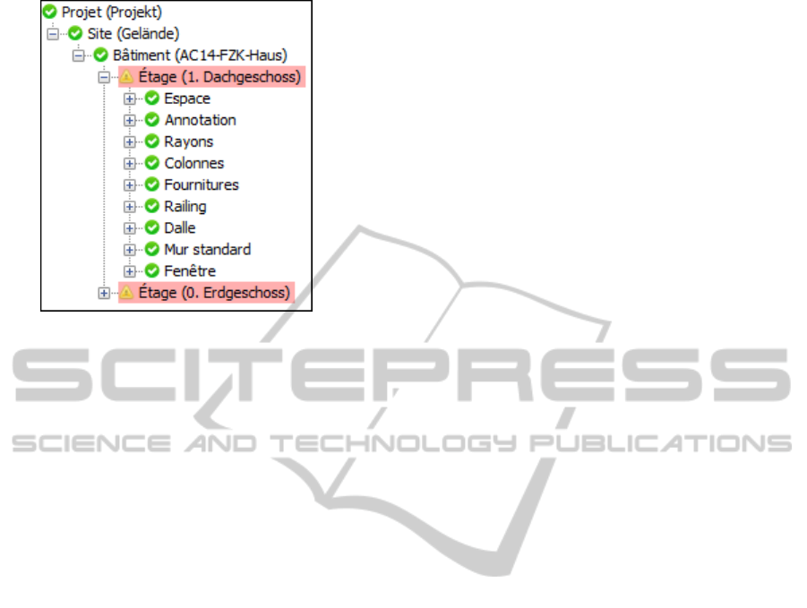
Figure 2: Example of a semantic representation of an IFC.
there are two kinds of agents’ spawners: the first one
spawns agents always on the same point in space and
the second one spawns agent randomly positioned on
a given surface. In this case, the semantics extracted
from the IFC will be used to determine what kind an
agents’ spawner that needs to be used. For example, if
the concept of agents’ spawner is associated to an Ifc-
Space, the spawner will be set as an area spawner that
will be able to spawn agents anywhere in the given
space. In the same manner, if the concept is associ-
ated to an IfcDoor (for example the door that repre-
sents the main entrance) the spawner will only spawn
agents on the exact position of this door.
In addition to performing associations to SFG
concepts, the user can also add some semantic con-
straints to RDF elements. To illustrate this principle,
we use the case of a simulation in which two kinds of
agents can progress, respectively named type A and
type B. The user can, for example, add constraints on
some door to specify that this instance of a door can
only be opened by type A agents. When the simu-
lation will be executed, type A agents will thus see
these doors as crossable elements while type B agents
will see these doors as obstacles. Another example
of constraint is that only type A agents will be al-
lowed to lock or unlock certain instances of doors,
type B agents’ permissions to use the passages will
thus evolve during the run of the simulation. In all
these cases, the COLLADA file will contain the geo-
metrical representation of the door, and the RDF file
will contain the fact that it is a door (and all informa-
tion that stem from it such as “ability to open it”, etc.)
and also constraints on these properties, such as the
fact that the door can effectively by opened, but only
by type A agents.
Finally, each action made by the user is stored by a
profile management module. This module will retain,
for each action, the semantic context and the action
of the user. These profiles are used to propose to the
user to try to perform automatically actions that the
user could do to set a simulation.
3.4 Architecture
The main part of the proposed software is about the
loading the IFC file (Figure 3). Two libraries are used.
The first one is dedicated to load the IFC structure in
memory according to their specifications. The sec-
ond one loads the geometry in a directly usable shape
structure and not in geometry description that need to
be processed.
A central kernel was developed to manage and
launch these two libraries, and link them to get the
shape representation of a given IFC element from the
specification-compliant memory representation. This
kernel also manages the generation of the JaSIM sce-
nario elements. It also allows communication with the
Graphical User Interface (GUI) to update links and
other data according to user actions.
This kernel is not dependent on the GUI and can
thus be used with another GUI or other user interac-
tion manner. The application structure is shown on
Figure 4. As shown on mentioned Figure, the kernel
loads the IFC file in order to extract IFC objects and
geometry that are put respectively in the display tree
and three-dimensional display. The developed GUI
allows to interact with the IFC structure or selection
and only calls kernel functionalities. It can thus be
easily replaced by other user interaction methods.
To perform the JaSIM file generation, the kernel
uses file generating modules shown in Figure 5. The
COLLADA
R
export module has been developed in
the scope of being reusable in any application. It
takes as input a Java3D scene graph (built from the
IFC files) and generate the COLLADA
R
schema that
corresponds to the given structure. Each Java3D el-
ement can be associated to some extra data that al-
lows us to keep a relation between the IFC objects
and the purely geometrical objects, i.e. GUID of IFC
objects is postponed in the COLLADA structure. The
SFG (JaSIM Scenario Configuration) generator mod-
ule parses the IFC data structure of our kernel to re-
trieve associations to SFG concepts and uses IFC ele-
ments’ description to get the geometrical position and
then generate the SFG file.
Finally, profile management is done by the ker-
nel. It updates the profile at each selection and re-use
the profile on the IFC loading to perform associations.
The profile update process is illustrated on Figure 6.
SEMANTIC MANAGEMENT OF INTELLIGENT MULTI-AGENTS SYSTEMS IN A 3D ENVIRONMENT
95
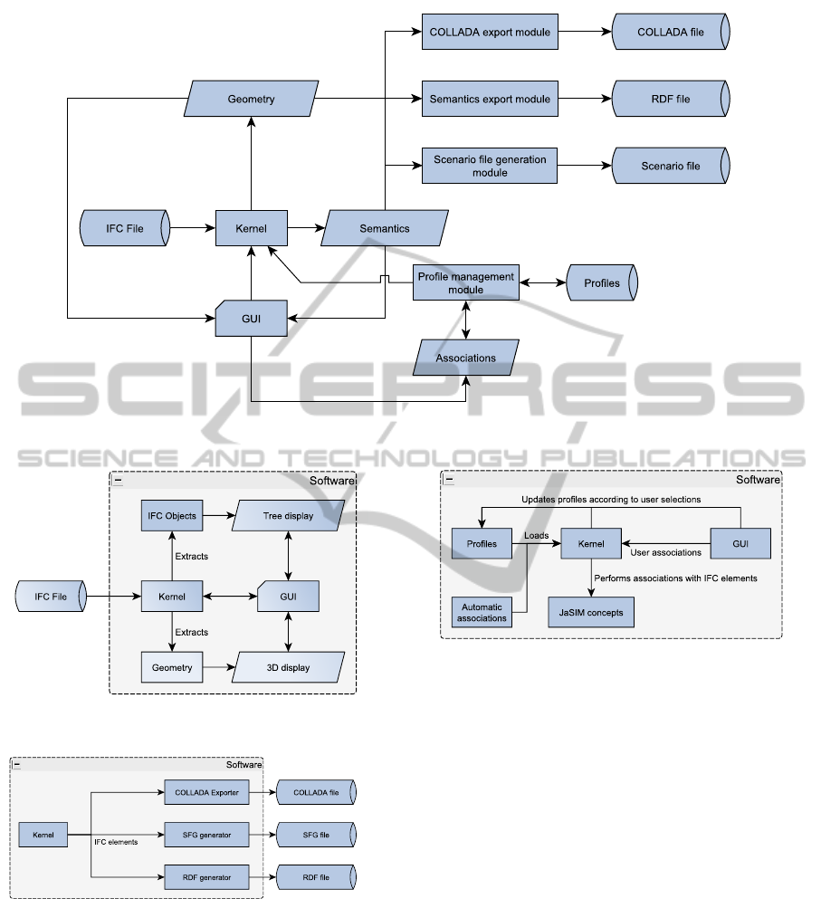
Figure 3: Global chart of our proposal.
Figure 4: Kernel centered architecture of our proposal.
Figure 5: File generation process.
4 CONCLUSIONS & FUTURE
WORKS
This paper discusses an ongoing research on the de-
sign of a multi-agent system based on a semantic in-
dexing of IFC objects. This paper presents the use of
IFC files to generate a MAS environment. These files
Figure 6: Profile management process.
are based on objects’ description merging semantics
and 3D geometries. Our work is done in order to test
the viability of the usage of IFC files in MAS simula-
tion domain.
Using IFC files as a starting point in MAS simula-
tion is beneficial according to the quality of the data,
which are always up-to-date. A simulation can be ex-
ecuted as soon as the building is designed to test the
quality and the level of compliance of such design.
Moreover, using BIM as a MAS input also enables
to bring a high level of semantic information to the
environment that can be used by the agents in turn.
The focus of this paper is on the semantic analysis
of IFC objects composing the 3D environment. It is
used to select and set up 3D objects and elements of
simulation scenarios. The result of this process gener-
ates semi-automatically and dynamically input files to
the JaSIM environment that performs the simulation
at the end. Our next goal is to improve our software to
get a better automation in the selection process. We
are developing an ontology-based IFC. The first re-
KEOD 2011 - International Conference on Knowledge Engineering and Ontology Development
96
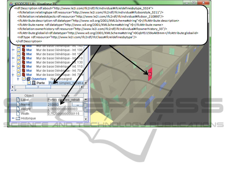
Figure 7: Example of RDF representation of IFC Object.
sults of this work are the translation of the building
objects into COLLADA and RDF files as depicted in
Figure 7.
This ontology will be used to describe associa-
tions to support more parameters and build rules, in-
cluding the management of the context. For exam-
ple, in our environment, doors and windows are both
opening elements and these elements can be seen by
the agents as crossable elements to get out from a
room. Nevertheless, is a window still a valid exit if
this window is on the 6th floor? Rules will make it
possible to perform a better classification of the ele-
ments and to apply several restrictions and filters on
the associations. Finally, this architecture will help
to apply fine associations and to improve the environ-
ment, or at least the simulation scenario.
ACKNOWLEDGEMENTS
This work is funded by the region of Franche Comt
´
e
and receive grants from a cooperative project between
the Franche Comt
´
e and the Bourgogne. Thanks to the
Checksem and SeT teams and Jordan Simonot for his
help in the COLLADA export part of this project.
REFERENCES
Cruz, C. and Nicolle, C. (2005). 3d reconstruction based
on semantic information for architectural applications.
Schriftenreihe Informations- und Messtechnick.
Cruz, C. and Nicolle, C. (2008). Cad software and inter-
operability. Encyclopedia of Information Science and
Technology Second Edition (8-Volume Set).
Cruz, C. and Nicolle, C. (2010). Active3d: Semantic and
multimedia merging for facility management. 6th In-
ternational Conference on Web Information Systems
and Technologies.
De Paiva, D., Vieira, R., and Musse, S. (2005). Ontology-
based crowd simulation for normal life situations. In
Computer Graphics International 2005, pages 221–
226. IEEE.
Ferber, J. (1995). Les Syst
`
emes Multi-Agents : vers une
intelligence collective. InterEditions.
Galland, S., Gaud, N., Demange, J., and Koukam, A.
(2009). Environment model for multiagent-based
simulation of 3d urban systems. In the 7th Euro-
pean Workshop on Multi-Agent Systems, Ayia Napa,
Cyprus.
Gutierrez, M., Thalmann, D., and Vexo, F. (2005). Seman-
tic virtual environments with adaptive multimodal in-
terfaces. In Multimedia Modelling Conference, 2005.
MMM 2005. Proceedings of the 11th International,
pages 277–283. IEEE.
Lugrin, J. and Cavazza, M. (2007). Making sense of virtual
environments: action representation, grounding and
common sense. In Proceedings of the International
SEMANTIC MANAGEMENT OF INTELLIGENT MULTI-AGENTS SYSTEMS IN A 3D ENVIRONMENT
97

Conference on Intelligent User Interfaces, Honolulu,
Hawaii, USA, pages 225–234.
Vanlande, R., Cruz, C., and Nicolle, C. (2003). Managing
ifc for civil engineering projects. In Proceedings of the
twelfth international conference on Information and
knowledge management, pages 179–181. ACM.
Vanlande, R., Nicolle, C., and Cruz, C. (2008). IFC and
building lifecycle management. Automation in Con-
struction, 18(1):70–78.
Weyns, D., Ominici, A., and Odell, J. (2007). Environ-
ment as a first-class abstraction in multi-agent sys-
tems. Journal on Autonomous Agents and Multi-Agent
Systems, 14(1):5–30.
Weyns, D., Parunak, H., Michel, F., Holvo
¨
et, T., and Ferber,
J. (2006). Environments for multiagent systems state-
of-the-art and research challenges. In Third Interna-
tional Workshop E4MAS, volume 4389, pages 1–47.
Springer.
Yersin, B., Maım, J., de Heras Ciechomski, P., Schertenleib,
S., and Thalmann, D. (2005). Steering a virtual crowd
based on a semantically augmented navigation graph.
In Proc. The First International Workshop on Crowd
Simulation (V-CROWDS’05), Lausanne, Switzerland,
pages 169–178. Citeseer.
KEOD 2011 - International Conference on Knowledge Engineering and Ontology Development
98
