
ASSEMBLY SIMULATION THROUGH A DIGITAL MOCK-UP
APPLICATION
Giampaolo Pascali, Angelo Corallo, Mariangela Lazoi and Alessandro Margherita
EuroMediterranean Incubator, University of Salento, Via Monteroni s.n., Lecce, Italy
Keywords: Design for assembly, Digital mock-up, Naval sector.
Abstract: “Design for X” includes a set of techniques to realize the best product yet during the design avoiding re-
works and loose of time and money. Among these, the design for assembly covers an important role and
aims to design a product “thinking” to the physical assembling moment. Digital Mock-Up (DMU) is a
process to enhance assembly feasibility and efficiency through specific design analysis and allow re-
producing a product virtual assembling. Based on an action research based on a collaboration among
company and university researchers, the paper aims to describe the development of a DMU application in a
naval Italian aerospace company to improve a ship fuel system assembling. Technical features of the
application are described.
1 INTRODUCTION
Different authors face the topics of the new product
development phases (Clark, Wheelright, 1995;
Crawford, Di Benedetto, 2003; Ulrich, Eppinger,
2007; Ribbens, 2000; Rosenau et al., 1996),
everyone specify such phase that goes from the
conceptualization until the production trough the
engineering. Ulrich and Eppinger (2007) suggest
five phases: 0. Planning, 1. Concept Development,
2. System Level Design, 3. Detail Design, 4. Test, 5.
Production. Specially, the Design Phase defines the
new product and prepares the work on which the
manufacturing units will impact (Ulrich and
Eppinger, 2007). The main objective in the product
design is to create a product architecture directly
linked with his functionalities. The creativity in the
first phase of conceptualization has to be translated
in a set of wished functions and blended in the
product architecture through the design in order to
facilitate and optimize the manufacturing and the
following maintenance operations providing an
optimized product. (Ribbens, 2000).
In the ‘design for x’ family, design for assembly
(DFA) is a particularly relevant process/approach by
which product assembly issues (mostly number of
parts, their insertion and orientation) are addressed
in the early design phase, with the goal to reduce
overall assembly cost, time and complexity. Among
company processes, the activities for assembling
individual parts to obtain the final product are
crucial as they use over 50% of total production
time, with costs varying from 20% to 40% for a
single unit. The use of DFA can improve
significantly such performance and several methods
have been developed at this purpose (Miyakawa and
Ohashi, 1986; Boothroyd and Dewhurst, 1986;
Holbrook and Sackett, 1988). The research on DFA
is based on the premise that the lowest assembly cost
can be achieved by designing a product in such a
way that it can be economically assembled by the
most appropriate assembly system. (Boothroyd and
Dewhurst, 1986).
Digital Mock-up is used to support design for
assembly providing assembly simulations that can
be used to address changes in product design and
support the physical assembly phase.
The naval industry is an interesting context of
research. Particular dynamics and routine are
peculiarities of this sector and cannot be found in
other industry. The products are very complex and
require high-technological knowledge and skills.
Design for Assembly and Digital Mock-Up
application can support the development of naval
system improving the company performance.
Based on an action research carried by
Università del Salento and Avio S.p.A., the
commercial application Teamcenter Visualization
Mock Up (VISMOCKUP) has been integrated in the
492
Pascali G., Corallo A., Lazoi M. and Margherita A..
ASSEMBLY SIMULATION THROUGH A DIGITAL MOCK-UP APPLICATION.
DOI: 10.5220/0003650304920497
In Proceedings of the 8th International Conference on Informatics in Control, Automation and Robotics (MSIE-2011), pages 492-497
ISBN: 978-989-8425-75-1
Copyright
c
2011 SCITEPRESS (Science and Technology Publications, Lda.)

company CAD system (NX). The paper aims to
answer the question “How is characterized a Digital
Mock-Up application in a naval company?”. The
paper shows criticalities and benefits from the
integration of Digital Mock-Up and CAD
environment in a unique Product Lifecycle
Management System.
In the next section of the paper the Digital Mock-
Up process is described, further insights from the
research design are highlighted and the method used
and application context are described. Another
section is dedicated to the mock-up application
description and finally, conclusions are provided
underling the technological limits of the developed
solution.
2 DIGITAL MOCK-UP
In the last years, there has been a great development
of digital technologies to verify product lifecycle
processes and reduce the need (and thus the costs)
for physical prototypes. Information technologies
can contribute not only to efficiency improvements
but also to improved hypothesis creation capabilities
in engineers and organizations through technical
features such as full visualization, digital pre-
assembly and simulation (Baba and Nobeoka, 1998).
In particular, digital mock-up (DMU) allows
designers to investigate the assembly feasibility of a
product and the constraints imposed by
manufacturing processes. DMU allows the user to
represent the structure of a product and the accurate
position of its geometry, and enables a
multidisciplinary presentation of assembly processes
and analysis (design ‘in context’) such as insertion,
view and collision.
Through DMU, it is possible to obtain a virtual
representation of a product and simulate the shape
and spatial positioning of its components or
subsystems, as well as of the necessary production
tools. By providing the basic representation of a
product, DMU permits to share the core product data
that the different company areas and disciplines use
to collaborate.
DMU has been extensively applied in different
industries such as automotive (Rooks, 1998) and
aerospace. Ford Motor Company is today strongly
involved in the adoption of virtual manufacturing
tools and processes designed to catch possible
manufacture concerns by simulating automotive
performance. An optimized product development
process based on the use of DMU and rapid
prototyping has been defined in the automotive with
the aim to fulfil goals of time and cost reduction, and
quality improvement (Döllner, Kellner and Tegel,
2000).
Shipbuilding is another interesting field for
applying virtual assembly features as it requires a
sophisticated product information model to achieve
the seamless flow of product information. A DMU
system that builds a prototype in a computer has
been proposed for consistent quality control. The
system can simulate models and assemblies on-the-
fly as well as project real-world manufacturability
without the expense and time required to make a
physical mock-up (Won Don, Jong-Ho and Ju Yong,
2007).
3 RESEARCH DESIGN
3.1 Research Method
The study is carried out through an action research
based on an inductive approach in which problems
and solutions have been deducted from observation
of the organizational practices (Bryman, Bell, 2007;
Thomas, 2006; O’Brien, 2001) and working together
to develop the final application. Working with Avio
in several research projects, the researchers of
Università del Salento are very confident with the
company problems and ICT used. The DMU project
has been launched from Avio to improve its
products design through the integration of
VISMOCKUP and the NX CAD system in a way to
work in the direction of a product lifecycle
management system for the company. To develop
the DMU system, three phases have been
accomplished. In the first phase, an analysis has
been done to evaluate how realizes the integration
and its potentialities. A second phase has been of
development and the two software tools have been
integrated in order to guarantee the best performance
for the company. In a last phase, the DMU/CAD
integration has been tested. This phase has been
concluded with a positive results and the application
is widely used inside the company. This action
research is carried out by a team of engineers of
Avio S.p.A and researchers of University of Salento
and the results are presented in the paper in the form
of case study (Yin, 1994) to address the research
question: “How is characterized a Digital Mock-Up
application in a naval company?”. It is a single case
study that wants to express the experiences matured
from the collaboration beetwenn Avio and
Università del Salento in the context of DMU
highlighting the importance and high relevance of
ASSEMBLY SIMULATION THROUGH A DIGITAL MOCK-UP APPLICATION
493
this kind of system for the naval company. To
answer to the research question has been developed
a software solution and the related findings have
described highlighting technological aspects and
managerial implications.
3.2 Company Context
AVIO is a world leader in the design, production
and maintenance of aerospace propulsion
subsystems and components. A smaller part of the
company business is also dedicated to the naval
sector for which produces turbine modules and
automation systems to support the integrated control
of the platform. A central activity is related to
FREMM (Fregata Europea Multi-Missione), a
military ship designed by Fincantieri and DCN to
operate in anti-submarine, anti-air, and anti-ship
settings. In such activity, the company looks for
improving assembly feasibility and optimization of
the (transducer plate of the) fuel system, with the
aim to minimize overall assembly time and costs
while enhancing compliance and operators’ safety.
4 A DMU APPLICATION
Teamcenter Visualization Mockup (from now on
VisMockUp) is a real-time digital prototyping
solution that includes interactive 3D viewing and
robust advanced analysis of large product
assemblies.
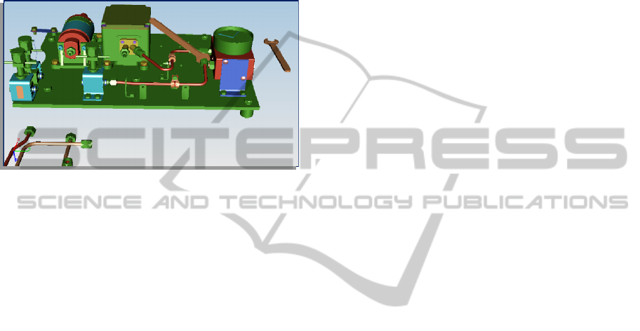
Three-dimensional solid models of the
components of the FREMM fuel system transducer
plate were created in UGS NX 2.0. However,
VisMockUp cannot access directly the solid model
data saved in the NX file format. For this reason, the
solid models were exported in JT file format using
the translator provided by NX. We made
modifications on the configuration of the NX
translator (called PVTRANS) in order to increase
reliability in assembly and clearance simulation. We
have used a PER_PART structure option to obtain a
JT file for the assembly and a directory containing
the JT parts.
JT file format is capable of storing an arbitrary
number of faceted representations with varying
levels of detail (LODs) We have defined two LODs
and set the chordalOption to the ABSOLUTE value
in order to obtain a constant chordal value in the
two LODs defined. In this way, the maximum
absolute distance that a line segment may deviate
from the smooth curve is approximately constant for
each part and independent from the part size. This
distance is expressed in the same unit of measure as
the part. For the two LOD defined we have set a
chordal value of 0.2 and 0.5 millimetres.
Furthermore the second LOD defined has forty
percent less or fewer polygons respect the first
(because its Simplify option has been set to 0.4).
Finally we have used a lossless compression for the
first LOD and a lossy compression in the second
LOD.
VisMockUp alternate hierarchies are generally
used to reorganize product assembly models
according to the specific design needs. We used
alternate hierarchies in order to represent the
assembly steps. In particular, each component of
this alternate hierarchy corresponds to an assembly
step. An assembly step contains the component to
be mounted at this step, the fasteners used and a
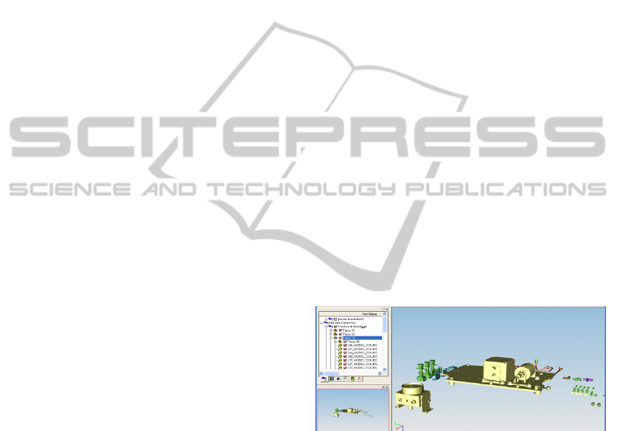
reference to the previous assembly step. In Fig. 3, it
is showed a representation of an assembly step in
which the transducer is being installed upon the
plate. The elements highlighted outside the plate are
the transducer to be mounted and the fasteners used
(four screws are visible). This approach was chosen
to take into consideration both the current element
to be mounted and the target assembly on which the
element is mounted. Each step defined is re-mapped
in the VisMockUp animation environment that is
used to implement the path defined by the DFA
procedure.
Figure 1: An assembly step.
The animation system within VisMockUp is
organized by events which are generally organized
in a sequence, unless there are changes in the
interdependencies among the events. Each event
contains a set of actions which are executed in a
concurrent or sequential way according to what has
been specified in the event timeline. In particular,
VisMockUp supports different types of actions
which can be visualized to make an animation. For
instance, the liner path action is used to define a
path that translates and/or rotates the selected parts
along a path that is created in the 3D view. The
camera action is used to rotate, pan, and zoom the
view of the model whereas the snapshot action is
ICINCO 2011 - 8th International Conference on Informatics in Control, Automation and Robotics
494
used to rotate, pan, and zoom the view and also to
set the visibility and transformation of parts. Finally,
the text action is used to add text mark-up to the
view, either anchored to a part or unanchored.
In our application, the assembly simulation at
each event coincides with an assembly step as
defined in the assembly hierarchy. Each event
should thus contain at least linear path actions which
implement a real assembly path and a snapshot
action to establish the initial layout of the assembly
step. In this way, it is possible to execute each
assembly step separately from others. It is important
to remark that the layout of a given step is obtained
from the end of the execution of the previous step.
As an option, an event can contain text and camera
actions to ease up the understanding and
visualization of the assembly simulation.
Another important action for motion simulation
is the action addressed to execute VFM files. These
are files containing a set of discrete positions of the
part to be moved, without interpolation among the
points representing the position of the part. There are
several ways to obtain a VFM file, for instance by
applying transformation on the part and capturing its
position or by using an automated functionality
provided by VisMockUp (called “path planning”).
This functionality identifies extraction paths for
parts or assemblies that need to be removed from
models for maintenance reasons. In particular, this
functionality generates a collision-free extraction
path in the form of a VFM file by specifying the
parts to be extracted and the parts to be avoided, and
a set of “key positions” of extracted parts. The key
positions must be at least two: a “start” position and
an “end” position. Intermediate positions can also be
defined to constrain the path direction. However,
there are several limitations in the use of VFM files.
In particular, they cannot be edited once defined and
it’s not possible to simplify them through
interpolation. We have also used the “path planning”
functionality to discover if a de-assembly path exists
for a particular component and then to establish
manually the related assembly path though the use
of the linear path action.
Once the initial layout of an assembly step has
been defined (snapshot action), it is possible to
define the assembly paths through the use of a linear
path action. A path consists of a series of control
points (nodes) connected by segments. There are
several ways to add a control point to a path: a) by
picking points directly on the 3D model (a feature
called pick mode); b) by using a dedicated node
creation panel; or c) by selecting the component to
be moved along the path and applying directly on
transformations.
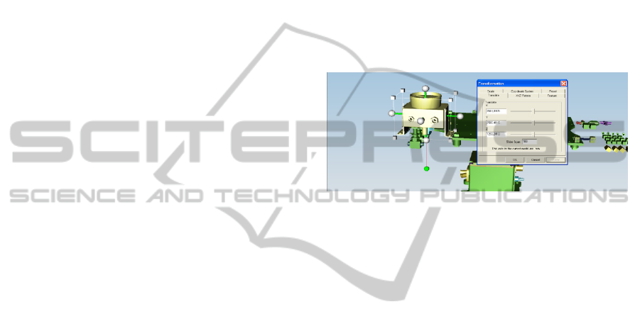
The control of one point’s coordinates is
obtained through the use of a manipulator or
transformation window (figure 4) in which it is
possible to precisely characterize the current
manipulator‘s position and orientation. Since the
manipulator and the part coincide, this also
determines the part’s position (x, y, z) and its spin
angles (θ
x
, θ
y
, θ
z
) which refer to a reference
coordinates’ system defined in the NX CAD
environment. VisMockUp doesn’t allow to estimate
the path duration time, which has been therefore
deducted based on the results of the DFA analysis.
Figure 2: Manipulator and transformation window.
Once an assembly path for the components is
established, they undergo a test for clearance
analysis. Clearance analysis identifies points of
contact and/or penetration among parts or groups of
parts. We can define clearance as the distance
between a pair of items in which there is no physical
interference. VisMockUp allows to specify a
clearance distance. All the items below this distance
(including contacts and penetrating items) are
identified and signalled to the user. VisMockUp
allows both static and dynamic clearance detection.
By setting the dynamic clearance analysis option,
when components are selected and the path
associated with them is executed, all the parts that
are within a predefined range from active parts are
analyzed. For the clearance analysis, we have
imposed to the calculator to use NURBS for the
calculation of the points of contact in order to obtain
a better approximation respect to the JT tessellated
data.
If a collision occurs, the colliding path has to be
modified in order to make it collision-free. There are
some collisions which are acceptable and that the
engineers should be capable to identify (e.g. a screw
that collides with its screwed hole).
To make the assembly simulation more reliable,
we also developed the tools used in the assembly
process. In particular, the tools have been modelled
in NX CAD environment, according to the Italian
UNI standard and using NX parts families. For each
ASSEMBLY SIMULATION THROUGH A DIGITAL MOCK-UP APPLICATION
495
type of tool, a part family was developed to allow
the user to obtain the necessary tool by varying some
typical parameters. Naturally, parameters are
selected by the user in a way to obtain tools
available on the market. Figure 5 shows the sketch
of part families realized in NX and which represents
single open end wrench. The process of importing
from NX to VisMockUp has been described in
paragraph 3.1.
Figure 3: Single open end wrench used in assembly
simulation.
Once an assembly step has been verified, it is
possible to add the assembly instructions that the
operator must follow in order to execute that step.
We keep separated assembly path verification from
assembly text instruction. In fact, assembly
instructions are contained in a separated event
executed in parallel with its associated assembly
event. An assembly instruction contains the part
number of components to be mounted, the fasteners’
part number, and the assembly tool to be used. It is
also possible to specify the tightening torque for
fasteners such as a nuts or bolts and any other
technical information. The complete assembly
simulation, along with assembly instructions, can be
exported in a standard video file format (e.g. avi,
mpeg, etc.) and used for company training purposes.
4.1 Technological Limitations
There are some limitations in the version of
VisMockUp used for the application in AVIO. For
example, in the linear path creation it is not possible
to obtain a feature-based alignment for the path
nodes definition and it is not possible to realize a
simple screw hole alignment using a linear path pick
mode option. Indeed, it’s not possible to select the
hole and the screw centres as inferred points. A
possible workaround is to include in CAD models
some datum points in correspondence of the inferred
points of interest, so that they are present and
selectable in the relative JT files. Datum points
insertion, however, would involve extra work time
for designers who own CAD models. Another
limitation is the fact that flexible components are not
supported since all the components are treated as
rigid bodies. To address this problem, it could be
supposed that if a path exists for a flexible
component treated as a rigid body then it also exists
the path for the flexible component itself. However,
this is not always true and in particular for complex
wiring systems that need different assembly
procedures respect to rigid components. For those
limits the activity of DMU development has been
frozen. However, Avio actually uses the DMU
application knowing its limits. The limits above
described can be overcome by the subsequent
versions of the DMU tool that should provide
improved and ease of use functionalities.
Furthermore, immersive virtual reality technology
integration can be an interesting evolution of this
research that could be thus channelled towards the
integration, within the DMU environment. .
DMU allows the user to make some geometric
verification on product or its sub-system. Therefore,
purpose of a Digital Mock-up is all kind of
simulations concerning the geometric shape,
kinematics or design studies. Instead simulations
regarding product intrinsic functionalities (e.g.
performances) not related to geometric envelopes or
product components spatial position are excluded
form the DMU verifications. In this case other
simulation tools are needed.
5 CONCLUSIONS
Starting from the relevance of design for new
product development, the paper highlights the
importance of the Digital Mock-Up to provide
assembly simulation to improve the result of the
design phase of a new product.
The paper is a technical one and describes the
development of a Digital Mock-Up application in a
naval company. Limits of the application are related
to the technology used.
Future research will apply process based
performance measurement methods to assess how
the new technology impacted assembly processes.
REFERENCES
Baba, Y. and Nobeoka, K. (1998). Towards knowledge-
based product development: the 3-D CAD model of
knowledge creation. Research Policy, 26 (6), 643-659,
ICINCO 2011 - 8th International Conference on Informatics in Control, Automation and Robotics
496

Boothroyd, G. and Dewhurst, P. (1986). Product design
for assembly. Boothroyd Dewhurst, Wakefield, RI.
Bryman A., Bell E., (2007), Business Research Methods,
Oxford University Press, Oxford.
Clark, K. B., Wheelright S. C., (1995), The Product
Development Challenge: Competing Through Speed,
Quality, and Creativity, Harvard Business School
Press
Crawford, C. M., Di Benedetto, C. A., (2003), New
Product Management, McGraw Hill Higher Education
Döllner, G., Kellner, P. and Tegel, O. (2000). Digital
mock-up and rapid prototyping in automotive product
development. Journal of Integrated Design and
Process Science, 4 (1), 55-66.
Holbrook, A. E. K. and Sackett, P. J. (1988). Design for
assembly - guidelines for product design. Proceedings
9
th
International Conference on Assembly Automation,
London, UK.
Khan, Z. (2008). Design for assembly. Assembly
Automation, 28 (3), 200-206.
Miyakawa, S. and Ohashi, T. (1986). The Hitachi
assembly evaluation method (AEM). Proceedings of
the International Conference on Product Design for
Assembly, Newport, RI.
O'Brien, R., (2001), An Overview of the Methodological
Approach of Action Research, Roberto Richardson
Pessoa, Universidade Federal da Paraíba, Brazil.
Ribbens, J., (2000), Simultaneous Engineering for new
product development, John Wiley & Sons, Inc.
Rooks, B. (1998). Shorter product development time with
digital mock-up. Assembly automation, 18 (1), 34-38.
Thomas D., (2006), A General Inductive Approach for
Analyzing Qualitative Evaluation Data, American
Journal of Evaluation, Vol. 27, No. 2, pp. 237-246.
Ulrich, K. T., Eppinger, S. D., (2007), Product Design and
Development, McGraw Hill Education Singapore
Won Don, K., Jong-Ho, N. and Ju yong, P. (2007). A
digital mock-up system for construction of product
information model in shipbuilding process. Journal of
Ship Production, 23 (1), 7-16.
Yin, R. K., 1994, Case Study Research: Design and
Methods, Sage Pubblications.
ASSEMBLY SIMULATION THROUGH A DIGITAL MOCK-UP APPLICATION
497
