
INTERVAL TYPE-2 FUZZY CONTROLLER BASED ON SLIDING
MODE CONTROL FOR ROBOT ARM DRIVEN BY
ARTIFICIAL MUSCLES
A. Rezoug
1,3
, M. Hamerlain
1
, B. Tondu
2
and M. Tadjine
3
1
Division Robotique & Productique, Centre de Développement des Technologies Avancées
Cité 20 août 1956, BP. N° 17, Baba Hassen 16303, Alger, Algérie
2
Institut National des Sciences Appliquées de Toulouse (INSA), Laboratoire d'Analyse et l'Architecture des Systèmes
(LAAS), Groupe GEPETTO, Pôle RIA, Toulouse, France
3
Process Control Laboratory, Electrical Engineering Department, ENP Alger, 10 Av. Hassen Badi, B182, Alger, Algeria
Keywords: Artificial muscles, Type-2 fuzzy logic, Sliding mode control, Fuzzy sliding mode control.
Abstract: In this paper, we propose the application of an Interval Type-2 Fuzzy Sliding Mode Controller IT2FSMC
for 2 degrees of freedom robot arm actuated by pneumatic artificial muscles (PAM). A robust IT2FL
controller based on the Lyapunov stability condition of sliding mode control SMC was adopted. The
objectives of the control are: (1) to avoid the modelling problem in this type of robot, (2) to attenuate the
chattering effect of the SMC, (3) to reduce the rules number of the fuzzy control, (4) to guarantee the
stability and the robustness of the system and (5) to handle the uncertainties of the system. First joints of
robot are approximated by adequately linear differential equations; next we present the proposed IT2FSM
approach of control. In the last, this method has experimented and compared to an interval type-2 fuzzy
controller IT2FC in order to demonstrate its effectiveness.
1 INTRODUCTION
In the last years, some precision robotic tasks based
on the pneumatic artificial muscle (PAM) actuators
have been used (Lilly et al, 2005); (Lopez et al.,
2006); (Schmitt et al., 2007). The (PAMs) are
tubular pull-actuators with a special fibber
arrangement. The fibres form a diamond pattern in a
three-dimensional mesh structure, which allows the
actuator to contract when the internal pressure of the
hose is increased (Schmitt et al, 2007). Several
examples of (PARM) based robot arm can be cited,
for example: Lucy humanoid robot of the Bruxel
University (Verrelst, 2005) ISAC humanoid robot of
(Schröder et al, 2003.), the seven degrees of freedom
(7-DOF) robot manipulator of the INSA laboratory
(Tondu, 2007; Tondu, et al, 2009) and that of
FESTO company (Pomiers, 2003) and so on. These
systems present same advantages such as cheapness,
light weight, compliance and low power/weight. In
the opposite, because of the time varying inertia,
hysteresis and joints friction (Lopez et al, 2006), the
(PAMs) robot’s Arm belongs to the class of highly
nonlinear systems, where perfect known of their
parameters using conventional modelling techniques
is very delicate. For this raison currently, the major
challenge in pneumatic muscle applications is to
have a robust control. Several robust controls are
applied to the robot with artificial muscles, we can
mention: Sliding Mode Control (SMC) (Lopez et al.,
2006), Higher Order Sliding Mode Control (HOSM)
(Tondu et al., 2009) nonlinear control (Xiang, 2001)
and so on.
In the last few years, a new approach of the
Fuzzy Logic (FL) called Type-2 fuzzy logic (T2FL).
This type of fuzzy logic is firstly introduced by L.
Zadeh in 1975 (Castillo et al., 2008). The (T2FL) is
the generalization of the classical type-1 fuzzy logic.
Type-2 fuzzy sets is characterized by membership
grades that are themselves fuzzy (Wu et al., 2006).
The membership function (MF) of a type-2 fuzzy set
has a footprint of uncertainty (FOU), which
represents the uncertainties in the shape and position
of the type-1 fuzzy set (Castillo et al., 2008); (Wu et
al., 2006). The T2FL is given for handle the
uncertainties in the systems (Castillo et al., 2008).
461
Rezoug A., Hamerlain M., Tondu B. and Tadjine M..
INTERVAL TYPE-2 FUZZY CONTROLLER BASED ON SLIDING MODE CONTROL FOR ROBOT ARM DRIVEN BY ARTIFICIAL MUSCLES.
DOI: 10.5220/0003615604610469
In Proceedings of the 8th International Conference on Informatics in Control, Automation and Robotics (ANNIIP-2011), pages 461-469
ISBN: 978-989-8425-74-4
Copyright
c
2011 SCITEPRESS (Science and Technology Publications, Lda.)
Sliding Mode control (SMC) and Fuzzy Logic
(FL) are attractive control methods used in the cases
when we have a process that is difficult to model.
Fuzzy Sliding mode control (FSMC) is the
combination of the sliding mode control and the
fuzzy logic techniques. The objectives of this
combination are: (1) to decrease the chattering effect
caused by the discontinuous part of the SMC, and
(2) to reduce significantly the rules number of the
(FL) part. (FSMC) guaranteed more robustness
compared to the parameters, modelling uncertainties
and external disturbances. A little number of
combination of the (SMC) and the (IT2FL) exist in
the literature, for example: inverted pendulum and
Duffing dynamical system (Hsiao, 2008), SISO
nonlinear systems (Lin et al., 2010) chaotic system
(Roopaei et al., 2010); (Hwang et al., 2011).
This paper presents the experimental study of the
robust interval type-2 fuzzy sliding mode controller
for 2-DOF robot arm actuated by pneumatic
artificial muscles. This control scheme allows us to
avoid the nonlinear modelling problems and
guaranteed the stability and the robustness of the
robot.
For the best presentation of the work, the paper is
subdivided to five sections. After the introduction,
section two presents the 2-DOF robot arm and its
identification. Section three explains sliding mode
control and the type-2 fuzzy control. The proposed
controller with the reasoning method will be the
objective of section four, experimental results and
discussion are presented in the section five. Finally
the paper is closed by the conclusion.
2 ROBOT DESCRIPTION
AND PARAMATERS
IDENTIFICATION
2.1 Robot Description
The 2-DOF of the robot actuated by the pneumatics
muscles called McKibben muscles is presented in
the figure (1). This system is Robosoft product
dedicated to research and development actions
(Pomiers, 2003). We have chosen this robot for the
reason that is suitable for domestic’s application.
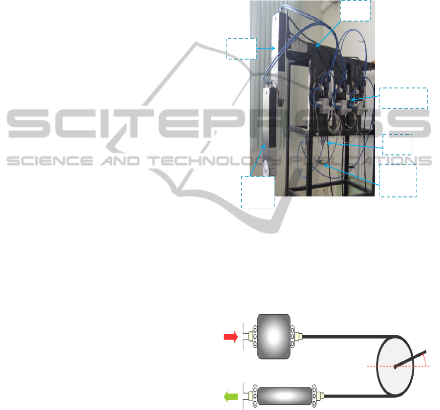
The used robot presented in figure 1 is composed by
several elements such as: (1) 4 FESTO fluidic
muscle, (2) 4 FESTO Proportional directional
control valve (3) 4 FESTO Pressure sensor, (4) 1
FESTO High-Flow D-Series Pneumatic Filters (5) 1
FESTO High-Flow D-Series Pneumatic Regulators
(6) 1 FESTO High-Flow D-Series Pneumatic
Lubricators Economical (7) 1 FESTO Branching
module (8) 1 FESTO Soft-start valve and (9) 1
FESTO Distributor block (Pomiers, 2003). The each
joint has 0.819 m of langue, and robot weight is
around of 15 Kg. The robot must be used at ambient
operating temperature of 0- 45°C.
J
oint2
Joint1
Distributors
Air
Source
Valve
Stem
Figure 1: 2-DOF robot arm actuated by the muscles.
As in skeletal muscles, two actuators are needed
to be coupled in order to generate a bidirectional
motion, one for each direction. This mechanical
motion can be obtained by modifying the pressure
ΔP in each muscle. The motion principle is shown in
Figure 2.
Figure 2: 1-Link arm robot actuated by the muscles.
Depicted in the figure 3, the robot control system
is composed by four subsystems so: in addition of
the robot, there exist a computer PC using for
including the program of control, a control box CB
charged for the communication between the PC and
the robot. The robot, PC and CB are connected by
CAN bus, finally the Air distributer is used as
alimentation of the robot.
+
ΔP
-
ΔP
ICINCO 2011 - 8th International Conference on Informatics in Control, Automation and Robotics
462
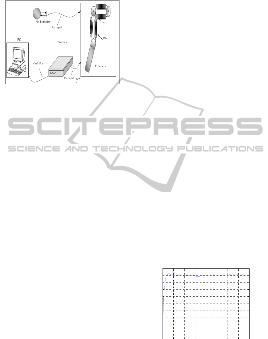
Figure 3: 1-Link arm robot actuated by the muscles.
2.2 Control Problems
In addition to the well known problems of robots
with PAM such as: hysteresis, joint friction and time
varying, in the case of our robot arm, there exist
many difficulties affect its control. We can give: The
pressure in each muscle is not identical. The
antagonistic system is affected by the temperature
and volume variations. The flow of each distributor
is supposed to be identical, but really they can have
a little difference from one to the other, the
characteristics of a muscle change slightly when the
number of operating cycle increases, these
phenomena’s will change the characteristics of the
system behaviour, i.e. the parameters of the system
are not exactly known and the modelling errors may
be appeared.
2.3 Robot Modelling and Parameters
Identification
The dynamic equations of n degrees of freedom
mechanical system using of the Lagrange equations
can be written as follow (Schmitt et al, 2007):
u
q
qqL
q
qqL
dt
d
,,
(1)
Where
q
denote the generalized coordinate vector,
q
denote the generalized velocity vector and t
denote the generalized force vector.
qqL
,
Is the
Lagrange function which is the difference of kinetic
energy and potential energy. The application of the
Lagrange equation for the robot system led to the
following general equation (Lopez et al, 2006):
)()()( uqgqhqJ
(2)
Where
q
,
q
and
q
are respectively the angular
position, velocity and acceleration vectors,
J
is the
inertial related matrix,
)(qh
is the vector of
centrifugal, coriolis and friction terms.
)(qg
is the
vector of gravity terms and
)(u
is the torque input
vector, u is the vector of control.
For one axis, the coriolis forces due to the
interaction with other axis do not exist and the
centrifugal force present a null couple compared to
the axis of rotation. By considering gravity and
viscous frictions dominating, the equation of the
movement can always be written in the following
nonlinear form (Lopez et al, 2006):
)()()( uqqGqqCqJ
(3)
With:
qqCqh
)()(
,
qqGqg )()(
The movement equation can be rewritten as:
)()()(
111
uJqqGJqqCJq
(4)
Within a linear approximation, the equation (2) can
be written, assuming that the derivatives of the entry
are not involved (Lopez et al, 2006):
BUqAqAq
01
(5)
Where
)(
1
1
qCJA
,
)(
1
0
qGJA
and
)(
1
uJBU
are parameters of the robot model that should be
identified. The linear approximation was too the
objective of the work of (Tondu, 2007) for two
articulations of 7–DOF robot manipulator.
For the determination of the best linear model,
the dynamic behavior of the robot joints were
characterized by Pseudo Random Binary Sequence
(PABS) inputs, which is a popular signal used in the
identification of systems. The (PABS) is
characterized by its large spectrum of frequencies.
The adequate (PABS) is injected and result joint
angular displacement values output responses are
saved.
The following figures represent the experimental
results of the identification of the robot’s Joints:
(a)
0 2 4 6 8 10 12 14 16
-4
-2
0
2
4
6
8
10
12
14
16
Time [S]
Experimental and estimated responses of joint 1 [deg]
identification of
j
oint 1
Figure 4: Identification of the joint one (a) and joint two
(b) respectively.
INTERVAL TYPE-2 FUZZY CONTROLLER BASED ON SLIDING MODE CONTROL FOR ROBOT ARM DRIVEN
BY ARTIFICIAL MUSCLES
463

(b)
0 2 4 6 8 10 12 14 16
-4
-2
0
2
4
6
8
10
12
14
16
Time [S]
Experimental and estimated responses of joint 2 [deg]
identification of joints 2
Figure 4: Identification of the joint one (a) and joint two
(b) respectively. (cont.)
The graph of the model validation is illustrated in
Figure (4). The bleu lines represent the
approximated models responses and the black lines
are the real system outputs.
The corresponding polynomial parameters of
each joint are given by:
.2075)(7.8573,16),(
02010
diagaadiagA
9595)(5.6654,2.),(
12111
diagaadiagA
.0194)(15.3217,2),(
21
diagbbdiagB
From these results, the robot arm may be presented
in the state space linear multivariable equations:
tU
XtX
0194.2
0
0
0
0
0
3217.15
0
9595.22075.1600
0100
006654.58573.7
0001
XtY
100
000
0
1
(6)
It is very important to say that the obtained linear
model is not representative of the real robot. But,
this linearization is used in transitory step for
objective to apply the sliding mode control (SMC).
The SMC technique is very knowledge by its
robustness compared to systems poorly modeled
and/or has parameter variations, and/or external
disturbances.
3 INTERVAL TYPE-2 FUZZY
SLIDING MODE CONTROL
DESIGN
We divided this part in two steps. In the first one, we
design the conventional sliding mode control and an
interval type-2 fuzzy control, while the second
proposes the fuzzy sliding mode control approach
for the robot arm control.
3.1 Sliding Mode Control
A Sliding Mode Control is a Variable Structure
Control (VSC). Basically, VSC includes several
different continuous functions that map plant state to
a control surface. The switching among these
functions is determined by plant state which is
represented by a switching function (Xiang, 2001).
For the best presentation of the SMC, we
considering the MIMO system described by the
following state-space equation (Xinghuo et al,
2009):
tBUXFtX
(7)
Where:
tX
is
the vector of state variables,
XF
is
the vector of the non-linear equations of the system,
B
is the input matrix and
tU
is the vector of
control. The design of the sliding mode control
needed two steps.
3.1.1 The Choice of the Sliding Surface
The selected sliding surface for a MIMO system
given in (7) is generally obtained by (Xinghuo et al,
2009):
XSttXtXGtXS
a
d
,
(8)
Where:
tGXt
d
,
tGXtS
a
and
G is a
diagonal gain matrix.
The sliding surface is given usually by the
following linear hyper-plan function:
nnnn
ee
ee
S
S
tXS
1111
),(
(9)
Where
i
with ni 1
are constant positive
values.
Once the function of commutation is calculated
the problem of tracking need the conception of the
law control with the stat vector
)(tX
rested on the
sliding surface. In this case
0),( tXS
for only
0t
.
A suitable control
U has to be found so as to retain
the error
)(te
on the sliding surface. To achieve this
purpose, a positive Lyapunov function
V
is defined
as:
2
SS
sV
T
(10)
ICINCO 2011 - 8th International Conference on Informatics in Control, Automation and Robotics
464

The sufficient condition for the stability of the
system is given by:
0 SsignDS
dt
sdV
T
(11)
Where
D
is the positive-definite diagonal gain
matrix.
3.1.2 Control Law Design
The sliding mode control comports two terms which
are equivalent control and switching control:
tUtUtU
seq
(12)
tU
eq
Is the equivalent term of the sliding mode
control, i.e. the necessary known part of the control
system when
0S
, and it is gevin by the following
equation:
dt
d
XGFGBtU
eq
1
(13)
tU
s
Describes discontinues control part where it is
given by:
SKsignssignDGBU
s
)(.
1
(14)
In our case of control, we choose to not use the
equivalent control of the robot. We uses only the
discontinuous part of control given by equation (14),
this choose is imposed by the parameters variation
of the not possibility to its estimation exactly. The
equivalent control part will be compensated by the
interval type-2 fuzzy controller will be presented in
the later section of this paper.
3.2 Interval Type-2 Fuzzy Control
The idea of a type-2 fuzzy set (T2FS) was
introduced in (1975) by Prof. Zadeh (Castillo et al,
2008). This fuzzy set is an extension of the ordinary
fuzzy set named type-1 fuzzy logic set. The use of
(T2FS) is called type-2 Fuzzy Logic Systems
(T2FLSs), which are useful especially in the cases
where it is difficult to determine an exact and precise
(MF) and/or the measurement of uncertainties is
difficult or even impossible. By including the
footprint of uncertainty (FOU) the (MFs) of the
(T2FSs) become three dimensional forms. The
(FOU) provides an additional degree of freedom to
make it possible to directly model and handle
uncertainties (Castillo et al, 2008); (Wu et al., 2006).
Theoretically, an interval type-2 fuzzy set
(IT2FS)
A
~
in X is characterized as (Castillo et al,
2008; Wu et al., 2006):
x
x
Ju
Xx
x
Ju
uux
Xx
A /
1.01.0
/1),/(1
~
(15)
Where,
denotes the union over admissible
variables
x
and u ,
Xx
is the primary variable,
x
Ju
is the secondary variable, ]1,0[
x
J
is the
primary MF of x, for interval type-2 sets the
secondary grades of
A
~
all equal to 1 (Wu et al.,
2006).
The interval type-2 fuzzy controller consists of:
fuzzifier, an inference engine, rules base, type
reduction and a defuzzyfier. Rules may be provided
by an expert (i.e. a human).
Fuzzyfier: The fuzzifier maps a crisp input into a
type-2 fuzzy set
A
~
.
Rules: The structure of rules in a type-1 FLS and a
type-2 FLS is the same, but in the latter the
antecedents and the consequents will be represented
by type-2 fuzzy sets (Wu et al., 2006). The general
IF-THEN rules in this case is given by (Castillo et
al, 2006).
ii
pp
ii
GisuThenFisxAndAndFisxIFR
111
~
~
:
(16)
Fuzzy Inference Systems: Type-2 Fuzzy Inference
Systems can be used when the circumstances are too
uncertain to determine exact membership grades
(Cazarez-Castro et al. 2010). From the IT2FS point
of view, the fuzzy rule in (16) can be written as
(Castillo, 2008):
ii
p
ii
GFFR
~
~
~
:
1
(17)
From the IT2MF point of view, (17) is equivalent to
ueue
ii
a
i
G
a
F
p
a
R
~
~
1
,
(18)
where u denotes the Meet operation, p is the number
of input variables, and up
eFe
a
F
p
a
i
a
~
~
1
, which
results in an interval set described by (Tsai et al.,
2008)
:
efefeF
i
i
,
~
(19)
Where
ef
i
and
ef
i
be re-expressed as:
2
~
1
~
11
* eeef
ii
FF
i
2
~
1
~
11
* eeef
ii
FF
i
(20)
Where * denotes the product operation.
Type-reducer: The type-reducer generates a type-1
fuzzy set output, which is then converted in a crisp
output through the defuzzifier. This type-1 fuzzy set
is also an interval set, for the case of our FLS we
INTERVAL TYPE-2 FUZZY CONTROLLER BASED ON SLIDING MODE CONTROL FOR ROBOT ARM DRIVEN
BY ARTIFICIAL MUSCLES
465
used center of sets (cos) type reduction,
)(
cos
eU
which is expressed as (Castillo et al, 2008); (Wu et
al. 2006).
M
i
i
M
i
ii
f
M
M
fu
M
r
M
l
uuu
rl
f
uf
ff
ffuuuueU
M
MM
r
M
l
1
1
1
1
,
cos
/1,
,,],[)(
11
(21)
Defuzzifier: the average of
r
u and
l
u
, so the
defuzzified output of an interval singleton type-2
FLS is (Castillo et al, 2008; Wu et al., 2006):
2
lr
uu
y
(22)
3.3 Interval Type-2 Fuzzy Controller
based on Sliding Mode Control
Design
To realize the robust IT2FLC, we choose a
decentralised type-2 fuzzy controller with two inputs
and one output for each joint. The inputs of the
controller are the siding surface and its derivatives’
(
11
1
iiii
eeS
and
i
S
), the output is the control
law (u
fuzzy
) which should be applied to the muscles.
The membership functions of the fuzzy inputs
variables are chosen to be fully overlapped,
triangular, trapezoidal and symmetric for the upper
and lower membership functions. These (MFs) are
presented in the following figures:
(a)
NeZe
Ns
Z
s Ps
‐1‐0.4‐0.2‐0.100.10.20.4+1
(b)
NeZePe
sN
sZ
sP
‐1‐0.4‐0.20 +0.2+0.4+1
Figure 5: Inputs fuzzy controller (a) the sliding surface
and (b) its variation.
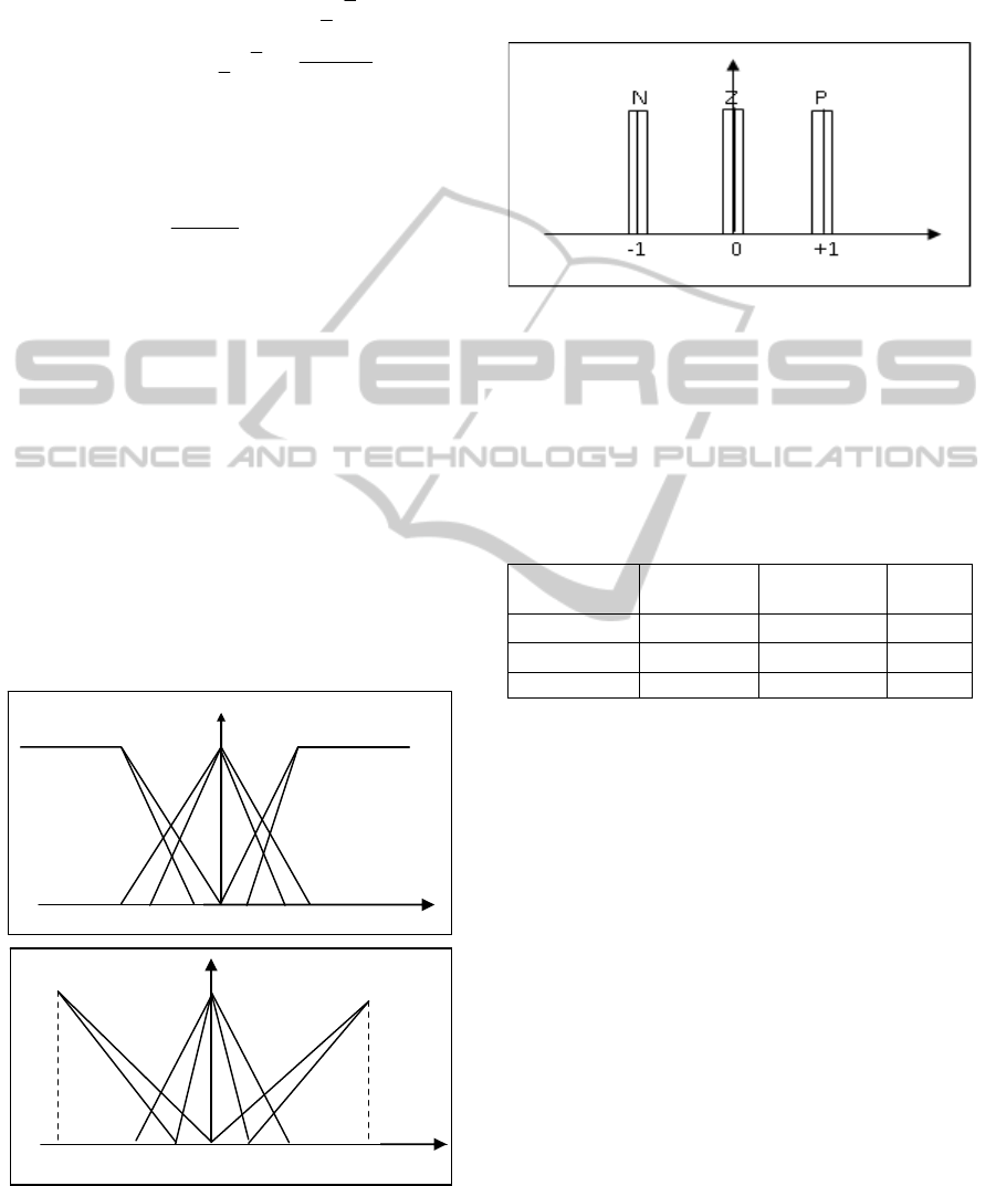
The following figure present the output MF
distributed on discourse universes. There are three
Type-1 MFs (N negative, Z zero, and P positive).
We choose Type-1 (MFs) in the objective to reduce
the time of fuzzy control computing:
Figure 6: Output singleton membership functions.
Based on the stability conditions given in the
general form by the equation (11), we can be led to
the diagonal type of If-Then reasoning rules
(Castillo, 2008), where through that we can able to
guarantee the stability of the global system.
Following table present our reasoning:
Table 1: Rule base.
S
s
N Z P
P Z PM P
Z NM Z PM
N N NM Z
The inference engine is the core of the fuzzy
system which handles the way in which rules are
combined. We used the general equation (20) to
realize the inference step.
In this paper, we are computing a Centroid type-
reducer method given by the equation (21). From the
type-reducer we obtain an interval set Ucos, must be
defuzzifier it.
The defuzifier is the last step of a type-2 fuzzy
control the output of the defuzzier is the crisp value
should be injected to the actuators of the robot arm,
the equation (22) is used to comput this value.
The full feedback control diagram of the
IT2SMC for the robot arm with PAM is presented in
the following figure:
ICINCO 2011 - 8th International Conference on Informatics in Control, Automation and Robotics
466
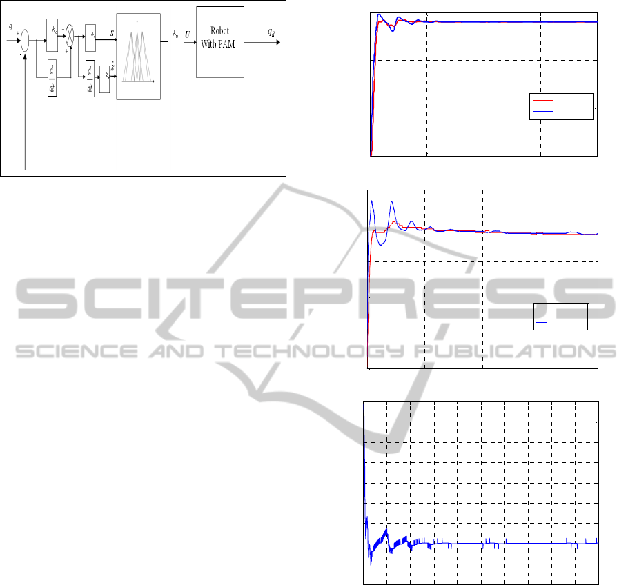
Figure 7: IT2 FSMC control for the robot with PAM.
4 EXPERIMENTAL RESULTS
AND DISCUSSES
Experimental results are used to examine the
feasibility and the validity of the proposed type-2
fuzzy sliding controller. The experimental are
accomplished by the implementation in C language
on the Pentium 4 PC. In order to handle efficiently
such a distributed architecture, the software system
is under Linux with an RTAI module and Syndex as
an interface more detailed has given in (Pomiers,
2003).
The regulation mode was adopted to test the
capability of the proposed controller to maintain the
imposed performances and the robustness. We want
that the 2-DOF robot attend the desired angular
position of 14 degree for the joint one and 10 degree
for the joint 2, with the initial position of zero degree
for all joints. We choose to present the joints
responses, the control signal and the inputs variables
(sliding surfaces) to show the attenuation of the
charting effect for the all joints of the robot arm.
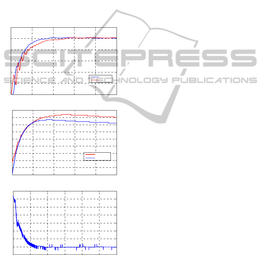
Figure 6 present the experimental results for the
control of the joint 1. Figure 7 gives the
experimental results obtained by the application of
the IT2FSMC. The fuzzy sliding mode controller
was implemented with a sampling time of 10 ms. In
the way of comparison, we used the IT1FSMC as
reference. The interval type-2 fuzzy logic controller
is used for objective to compare with the proposed
IT2SMC controller. The inputs of the IT2FC were
the error on angular position and its derivative. The
output in the pressure should be injected in the each
joint of the robot. The membership functions of the
IT2FC are similar with IT2FSMC.The following
figures present the results of joint 1.
(a)
0 5 10 15 20
0
5
10
15
Time [s]
angular position [degree].
angular position of Joint 1.
IT2FC
IT2FSMC
(b)
0 5 10 15 20
0
20
40
60
80
100
Time [s].
control signal [mB ar].
control signal of joint 1.
It2FLC
IT2FSMC
(c)
0 2 4 6 8 10 12 14 16 18 20
-20
-10
0
10
20
30
40
50
60
70
Time [s].
silding s urfac e.
sliding surface
Figure 8: (a) joint one angular position response for the
IT2FSMC (bleu) and IT2FC (red), (b) control signal for
the IT2FSMC (bleu) and IT2FC (red) and (c) the surface
variation.
For the IT2FSMC, we observe from the position
response curvature that the joint one tracked
adequately the imposed reference angle, with the
existence of satisfactory static and dynamic errors.
We can see from the figures of the control signal
like that of sliding surface the smoothes signals, and
then the chattering effect is attenuated. As the
IT2FSMC as IT2FC present the good results,
however, the IT2FSMC has the little Amelioration.
The control of the joint two is very difficult
compared to the joint one. We observe from the
INTERVAL TYPE-2 FUZZY CONTROLLER BASED ON SLIDING MODE CONTROL FOR ROBOT ARM DRIVEN
BY ARTIFICIAL MUSCLES
467
position response of the IT2FSMC that the joint two
tracked adequately the imposed reference angle,
with the existence of acceptable static and dynamic
errors. This joint present delay may be caused by the
gravitational effect. In the other hand we can see
from the figures of the control signal like that of
sliding surface the smoothes signals, which presents
the attenuation of the chattering effect. In the
opposite the IT2FC has not given the good results.
We can say that the IT2FSMC has given the better
results compared with the IT2FC specifically it is
shown in the joint 2.
The following figures present the results of joint 2:
(a)
0 5 10 15 20 25
0
2
4
6
8
10
12
Time [s].
angular posit i on [degree.
an
g
ular position of
j
oint 2.
IT2FSMC
IT2FC
(b)
0 5 10 15 20 25
0
10
20
30
40
50
60
70
80
90
Time [s ]
cont rol signal [mBar]
control signal of joint 2.
IT2FC
IT2FSMC
(c)
0 5 10 15 20 25 30
-10
0
10
20
30
40
50
60
70
Time [S].
surface.
surface evolution of Joint 2.
Figure 9: (a) Joint two angular position response for the
IT2FSMC (bleu) and IT2FC (red), (b) Control signal for
the IT2FSMC (bleu) and IT2FC (red) and (c) The surface
variation.
5 CONCLUSIONS
In this paper, an interval type-2 fuzzy controller
based on stability condition of the sliding mode
control for robotic arm actuated by artificial muscles
is proposed. This controller was implemented on
real time to the 2- DOF arm robot, to control of its
angular positions with a very little number of rules.
The experimental results shows that not only the
good tracking performance has been obtained, but
also the stability and the robustness have guaranteed
with a chattering effect have avoided. The proposed
IT2FSMC present superior performances compared
with an IT2FC. In future work, we will compare this
control approach with an others control techniques.
REFERENCES
Lilly J. H., and Yang, L., 2005. Sliding Mode Tracking for
Pneumatic Muscle Actuators in Opposing Pair
Configuration, IEEE transactions on control systems
technology, Vol. 13, No. 4.
Lopez P., Nouri, A. S., 2006. Théorie élémentaire et
pratique de la commande par les régimes glissants,
Springer-Verlag Berlin Heidelberg.
Schmitt J., Grabert F. and Raatz A., 2010. Design of a
Hyper-Flexible Assembly Robot Using Artificial
Muscles, Proc. Of IEEE int. conf. on robotics and
biomimrtics, Tianjin, china, PP. 897- 902.
Tondu B., Braikia, K., Chettouh, M. and Ippolito, S.,
2009. Second Order Sliding Mode Control for an
Anthropomorphic Robot-Arm driven with Pneumatic
Artificial Muscles, 9th IEEE-RAS International
Conference on Humanoid Robots, PP. 47 – 54.
Castillo, O. and Melin, P., 2008. Type-2 Fuzzy Logic:
Theory and Applications. Springer-Verlag Berlin
Heidelberg.
Wu, D. and Tan, W. W. 2006. A simplified type-2 fuzzy
logic controller for real-time control, ISA
Transactions, Vol. 45, No 4, PP. 503–516.
Hsiao, M. Y., 2008. Design of interval type-2 fuzzy
sliding-mode controller, Journal Information
Sciences: an International Journal archive Vol 178
(6).
Lin T. C., 2010. Based on interval type-2 fuzzy-neural
network direct adaptive sliding mode control for SISO
nonlinear systems, Commun Nonlinear Sci Numer
Simulat 15, PP. 4084–4099.
Roopaei, M., Sahraei, B. R., Lin, T. C. and Chen, M. C.,
2010. Synchronization of Two Different Chaotic
Systems Using Chattering-Free Adaptive Interval
Type-2 Fuzzy Sliding Mode Control, the 5th IEEE
Conf. on Industrial Electronics and Applications, PP.
121 – 126.
Xiang, F., Block-Oriented Nonlinear Control of
PneumaticActuator Systems, Doctoral thesis, Sweden
ICINCO 2011 - 8th International Conference on Informatics in Control, Automation and Robotics
468

University 2001.
Kaynak, O., Erbatur, K. and Ertugrul, M., 2001. The
Fusion of Computationally Intelligent Methodologies
and Sliding-Mode Control—A Survey, IEEE
Transactions on Industrial Electronics, Vol 48 (1), pp
4-17.
Nohe, R., Castro, C., Aguilar, L. T. and Castillo, O., 2010.
An Application of Fuzzy Lyapunov Synthesis in the
Design of Type-2 Fuzzy Logic Controllers, Soft
Computing in Industrial Applications, AISC 75, PP.
229–236.
Zhixiang, T., Hongtao, W., 2010. Hierarchical Terminal
Sliding Mode Control for Underactuated Space
Robots, International Conference on Machine Vision
and Human-machine Interface, PP. 195 - 198.
Pomiers, P., 2003, Pneumatic Muscles Robot Arm User’s
Guide, Robosoft S.A.
Brian, O. 1997. Fuzzy sliding mode control: critical
review, research report, oklahoma state university.
Tondu, B., 2007. Artificial Muscles for Humanoid Robots,
Humanoid Robots: Human-like Machines, Book
edited by: Matthias Hackel, pp. 89-122, Itech, Vienna,
Austria,
Wu, D., 2009, Intelligent systems for decision support,
Doctor of philosophy electrical engineering.
University of southern california.
Verrelst, B., 2005. A dynamic walking biped actuated by
pleated pneumatic artificial muscles: Basic concepts
and control issues, Doctor in de Toegepaste
Wetenschappen, Vrije Universiteit Brussel.
Schröder, J., Kawamura, G. K., and Dillmann, R., 2003.
Improved control of a humanoid arm driven by
pneumatic actuators, in Proceedings of Humanoids.
INTERVAL TYPE-2 FUZZY CONTROLLER BASED ON SLIDING MODE CONTROL FOR ROBOT ARM DRIVEN
BY ARTIFICIAL MUSCLES
469
