
BlueState
A Metamodel-based Execution Framework for UML State Machines
Alfredo Ortigosa and Carlos Rossi
E.T.S.I. Informatica, Universidad de Malaga, Campus de Teatinos, 29071 Malaga, Spain
Keywords:
State machines, UML, Code generation, MDE, CASE tool.
Abstract:
Most of the tools that generate code from UML state machines present a series of drawbacks, such as the
lack of conformity to the UML specification or the difficulty of integrating them in a real process of software
development and maintenance. In this work, we show how to overcome these drawbacks using BlueState, a
framework we have developed based on class metamodels. BlueState, apart from code generation, includes
debugging and real-time visual monitoring modules. The framework has been designed to be independent of
the modeling tool and makes it possible to generate code in different target languages.
1 INTRODUCTION
Modeling languages are really useful to clearly de-
fine dynamic behavior of systems. Among these lan-
guages, UML is the de facto standard for software
specification. More precisely, the state machine di-
agram is the UML diagram that offers the most possi-
bilities to define dynamic behavior.
Some CASE tools offer a direct transformation of
certain diagrams (like class diagrams) into object ori-
ented languages, yet these seldom occur with state di-
agrams, and high levelprogramminglanguages do not
include a framework for their implementation either.
There are some theoretical models used to trans-
form state machine diagrams into code, as well as
design patterns and some other tools that achieve a
partial transformation of UML state diagrams into
code. Nevertheless, these tools are scarce and usually
present the following drawbacks:
• Lack of UML compliance: There is no formal cor-
respondence with the UML specification. Thus,
tools cannot check the constraints defined in this
specification. Moreover, most tools do not incor-
porate all the elements defined by the UML spec-
ification and use models difficult to extend (to-
wards the inclusion of these elements).
All this diminishes the quality of the software
since the precision of the behavior specification
is lost in the code generation process.
• Many automatic code generators depend on a spe-
cific modeling tool.
• There is no clear division between the code that
implements the state diagram and the code that
must be added to complete the system’s own pro-
cesses. For this reason, it is usually difficult to
make changes in the diagram and transfer them
to the implementation. This makes the process of
software maintenance more complex.
• In general, they do not offer a monitoring and de-
bugging system which is essential for bug location
in state diagrams during software construction.
These drawbacks allow us to conclude that code
generation from UML state diagrams in real software
development has no satisfactory solution.
To advance a solution to this problem, we present
BlueState (Ortigosa and Rossi, 2011), a framework
for the implementation and execution of UML state
machine diagrams. This framework can be employed
in projects of diverse complexity, and is aimed at giv-
ing a solution to the shortcomings of the existing im-
plementation tools for UML state machine diagrams.
The advantages of our solution stem from its code
generation engine based on an intuitive and extensible
model that conforms exactly to the UML metamodel
specification. Thus, our approach also allows for the
validation of constraints of the UML specification.
One of our objectives has been to maintain in-
dependence from the modeling tool (using the XMI
standard as a reference) as well as from the target lan-
guage. To this end, BlueState uses an intermediate
structure thatallows for the generation of code in mul-
tiple languages.
226
Ortigosa A. and Rossi C..
BlueState - A Metamodel-based Execution Framework for UML State Machines.
DOI: 10.5220/0003609202260231
In Proceedings of the 6th International Conference on Software and Database Technologies (ICSOFT-2011), pages 226-231
ISBN: 978-989-8425-77-5
Copyright
c
2011 SCITEPRESS (Science and Technology Publications, Lda.)

Our contribution is not limited to mere code gen-
eration, but also includes modules for real-time de-
bugging, simulation and visual monitoring that, in our
opinion, make BlueState a real improvement over the
current solutions.
In the following section, we analyse the main code
generation techniques for state machines, thus justi-
fying our choice of the class metamodel as the base
technique. In section 3 a description of BlueState and
its usage context is carried out. Section 4 includes
a study of tools similar to BlueState that we use to
vouch for its quality. Finally we draw some conclu-
sions and explain our current and future lines of work.
2 IMPLEMENTATION
TECHNIQUES
There are diverse implementation techniques and de-
sign patterns that are aimed at translating the behav-
ior defined in UML state machine diagrams into code.
We will now analyse such techniques.
Traditional techniques are transition ta-
bles (Cargill, 1992), conditional statements (Dou-
glass, 1998) and the state design pattern (Gamma,
1995). These techniques are aimed at implementing
basic state diagrams and do not directly contemplate
important characteristics of the UML state diagrams,
such as composite states, guards, history states,
“doActivity” behaviors, choices, call events, etc.
Some works have sought to extend these tech-
niques or have created alternative models to solve
these problems and getting closer to the UML spec-
ification. For instance, in (Niaz and Tanaka, 2005)
the state pattern is extended to allow for more ele-
ments, such as composite states. In (Douglass, 1998;
Harel and Gery, 1997) more characteristics are added
to the conditional statements method. The transition
tables method is also used in (Kohler et al., 2000).
Other works (Samek and Montgomery, 2000; Pint´er
and Majzik, 2003) employ hierarchical models to deal
with composite states and other features. Several of
these models utilize non intuitive structures that do
not comply with the UML object-oriented approach,
which makes their understanding and extension com-
plicated.
Nevertheless, the class metamodel technique used
in this work solves these inconveniences, making the
implementation of the state machine diagram a natu-
ral process according to the UML specification.
The class metamodel technique for state dia-
grams (Knapp and Merz, 2002; Derezi´nska and Pil-
itowski, 2009; Mocek, 2010; North State Software,
2008) is an implementation technique less extended
than previously mentioned ones, but very powerful
and closer to the object-oriented paradigm.
Some works (Jakimi and Elkoutbi, 2009; Sterkin,
2008) explain that the syntax of object-oriented lan-
guages such as Java or C# does not allow us to es-
tablish a one-to-one mapping between concepts of
the state diagrams and language features. Therefore,
they indicate that it is necessary to use more com-
plex implementation mechanisms or other languages.
Nevertheless, using the class metamodel technique
it is possible to establish a nearly direct implemen-
tation of the UML state machine diagram (notwith-
standing the informal character of its semantics (Ob-
ject Management Group, 2009)) when we use an
object-oriented language and we add a simple ab-
straction level. That is even more important if we
take into account that the UML specification is given
by a class metamodel (Object Management Group,
2010b). We have reviewed the main implementa-
tion techniques concluding that the most rigorous and
efficient option would be to contemplate this meta-
model. The class metamodel technique has also been
adopted as the core of generic modeling frameworks
like EMF (Steinberg et al., 2009).
Another approach to the execution of a behaviorin
a system is the one proposed in the fUML work doc-
ument (Object Management Group, 2010a). In this
specification it is proposed to directly execute a model
with basic elements through a virtual machine. This
way, the use of an intermediate actions language pro-
vides independence from the target language (Object
Management Group, 2009).
This approach, still in beta phase, only includes a
limited set of the UML metamodel, without consider-
ing the state diagram, and needs to be materialized in
specific implementations. Also, this model requires
a level of abstraction that does not take advantage of
the potential of specific programming languages.
3 BlueState
BlueState is the execution framework for UML state
machine diagrams presented in this work. In this sec-
tion we present its class metamodel and its main mod-
ules, framed in their usage context.
3.1 Class Metamodel
Our theoretical basis is similar to EMF (Steinberg
et al., 2009), but we have eliminated a level of ab-
straction in search of specificity. In this way we aim
for a better adequacy to UML state machine diagrams
BlueState - A Metamodel-based Execution Framework for UML State Machines
227
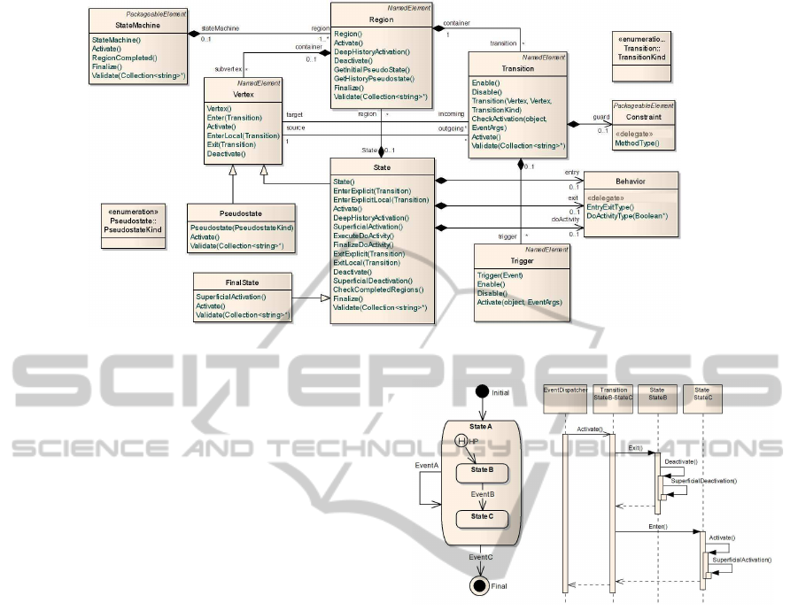
Figure 1: Subset of BlueState class metamodel.
and better performance, facilitating their integration
into real software developments.
BlueState class metamodel very accurately fits the
UML metamodel, as shown in Figure 1.
In this work we have used C# to implement the
class metamodel that defines UML state diagram.
This language has offered both the object orientation
concepts as other important mechanisms of concur-
rent execution and synchronism.
The most essential part of the implementation has
been translating the semantics of the metamodel into
specific operations in each class. Despite the informal
character of the semantics offered by the UML speci-
fication, it has been followed as rigorously as possible
As a result of this implementation we get a class
library (more specifically, .NET Framework library),
which should be referenced in the generated projects.
Following the class metamodel, the code gen-
erated by BlueState is very simple, composed ex-
clusively of object creation statements and property
assignations. The following lines of code are a
fragment of the implementation of the state diagram
shown in Figure 2.
State StateB = new State();
Transition Tran_StateB_StateC = new Transition();
Tran_StateB_StateC. Source = StateB;
CallEvent_EVENTB = new CallEvent();
CallEvent_EVENTB.Name = "EventB";
CallEvent_EVENTB.EvDispatcher = EvDispatcher_ED1;
The class metamodel is completed by a mecha-
nism for the reception and processing of events. In
this way, we have incorporated an event dispatcher
that ensures a run-to-completion execution.
The execution of a state diagram will consist
of calls to the operations of the elements involved
in each transition, together with the event reception
Figure 2: State machine and sequence of operations.
mechanism. Figure 2 shows an example of a state
diagram as well as a sequence of operations in the ac-
tivation of a transition (in this case, the state machine
is in StateB and EventB is received).
The elements of the UML state machines included
in BlueState are: simple and composite states, initial
pseudostates, final states, entry, exit and doActivity
state behaviors, guards, event calls, signals, local and
external transitions, regions and shallow and deep his-
tory pseudostates. So, BlueState allows for the defini-
tion of nearly every behavior in a state machine.
3.2 Usage Context
In this section we describe the workflow for the im-
plementation of a system using BlueState.
3.2.1 Design of the State Machine Diagram
The state machine diagram that represents the behav-
ior specified for the system will be initially designed
in the modeling tool that the user is accustomed to.
The specific code that has to be executed in state
ICSOFT 2011 - 6th International Conference on Software and Data Technologies
228
operations (entry, exit, doActivity) or guard condi-
tional statements, will be directly included in the state
diagram. At the moment this is a complicated task for
modeling tools, as there is a boundary between the de-
sign of the UML state diagram and the code in a spe-
cific programing language. To enhance the compati-
bility between modeling tools we have contemplated
the “name” attributes of these guards or operations to
indicate the methods or code in the target language.
3.2.2 Importing and Parsing XMI Documents
Once the state diagram is designed, the modeling tool
can export it into an XMI document. BlueState fa-
cilitates importing this document through a complete
XMI parser implemented ad hoc.
This parser allows the user to identify the informa-
tion of the state diagrams contained in the XMI doc-
ument. Once a state diagram is selected, it is trans-
formed into an object representation, using the class
model presented in the previous section. At this point,
we validate the constraints of the UML metamodel.
Although in the implementation of this parser we
have rigorously followed the XMI standard (Object
Management Group, 2011), it has also been necessary
to include some configuration parameters to increase
the compatibility with certain modeling tools. We
have checked that it works correctly with Enterprise
Architect (Sparx Systems, 2011), MagicDraw (No
Magic Inc., 2011), Altova Umodel (Altova, 2011) and
Visual Paradigm (Visual Paradigm Intl., 2011).
3.2.3 Automatic Code Generation
The following step will be to indicate the class for
which the code of the state diagram will be generated
and the target programming language.
Then, BlueState will automatically implement the
code for the selected class from the imported state
diagram. To this end, our code generation engine
uses the CodeDOM mechanism of the .NET Frame-
work (Microsoft Corp., 2011) with an intermediate
logic structure that is independent from the target lan-
guage. This way, BlueState generates C# and Visual
Basic .NET code and can be extended to C++, J# and
JScript.
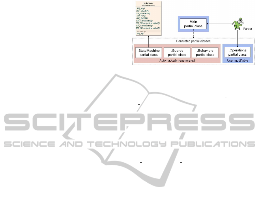
The partial class concept is utilized for a better
separation of the generated code with the code ex-
isting in the class. To that end, four partial classes
are created (see Figure 3). This structure facilitates
the use of BlueState in real software projects, since a
change in the state diagram will conveniently modify
these partial classes in a way transparent to the devel-
oper.
Figure 3: Generated partial classes.
Once the state diagram has been automatically im-
plemented, the initialization and execution of the state
machine only requires the calling to
SM init()
and
SM Run()
methods implemented in the target class.
3.2.4 Concurrent Execution of State Machines
and Event Sending
Another important characteristic added to our frame-
work is the possibility of parallel execution of state
machines and the sending of events between them.
Each implemented object has two methods
(
SM AEvent
and
SM SEvent
) for the reception of
events in synchronousor asynchronousmodes respec-
tively. These methods accept an operation name and
optional parameters.
In (Ortigosa and Rossi, 2011) some videos are in-
cluded with examples of concurrent execution of state
machines.
3.3 Simulator and Debugger
A major drawback in most tools is the inability to ver-
ify behavior models before their code its deployed. It
is well known that the cost of correcting an error is
much lower if it is detected in the modeling process.
To deal with this drawback, BlueState allows to
simulate the execution for any generated state dia-
gram. This simulation is controlled through a graphic
interface built dynamically with the events defined in
the diagram. During the simulation, these events can
be generated by clicking the associated buttons. Fig-
ure 4 shows a state machine diagram that is being
executed and a window of the simulator configured
automatically from that diagram. Also, this interface
allows us to trace the input and output of states and
adjust an execution delay to facilitate the monitoring.
Furthermore, a complete execution log is included. It
allows for the debugging or monitoring of each of the
elements involved in the state machine execution.
BlueState - A Metamodel-based Execution Framework for UML State Machines
229
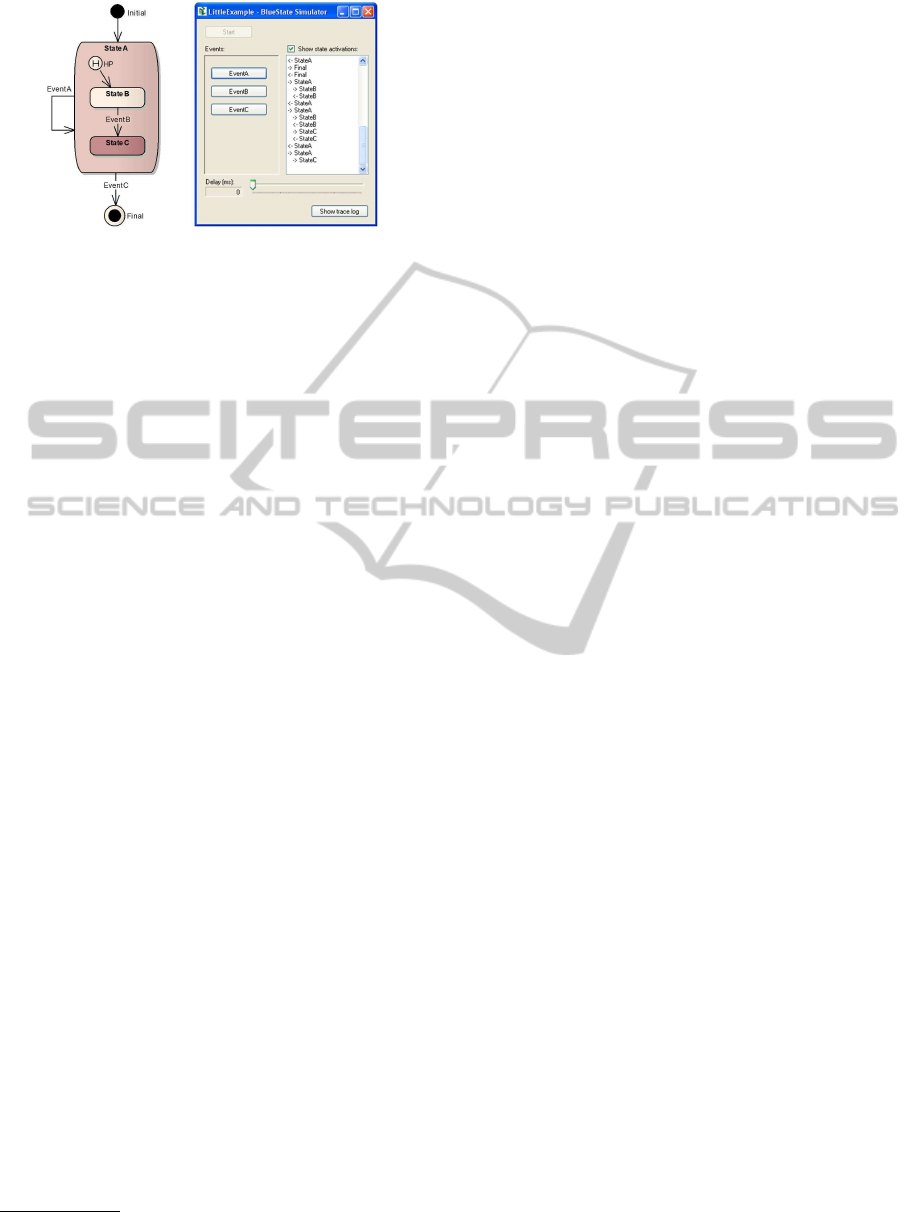
Figure 4: State machine simulation.
3.4 Real-time Visual Monitoring
The BlueState framework has been completed with an
important module that allows real-time visual mon-
itoring of state diagram execution. In this way,
the developer can graphically track the execution of
the state machine once deployed its associated code.
Thus, we facilitate the identification of elements of
the state machine design that are eventually causing
software malfunction. In our opinion, this is a very
useful feature that it is not present in most tools.
This module let us monitor both local and remote
execution of state machine diagrams. Also, it allows
the simultaneous execution of several state diagrams.
The visualization is carried out using an add-in
we developed for Enterprise Architect, which shows
graphically the active states and transitions of a state
diagram in execution. In (Ortigosa and Rossi, 2011)
some example videos are included.
4 RELATED WORKS AND TOOLS
In this section, we briefly analyze works and tools re-
lated with BlueState, focusing on features that facili-
tate the integration in a real software project.
1
• Modeling tool independence:
There are solutions meant to be independent from
a modeling tool and that generate code from state
diagrams contained in XMI files. BlueState is the
solution that best adapts to this idea, followed by
the SinelaboreRT solution (Mueller, 2011).
• Precise behavior:
BlueState stands for its high compliance with the
UML specification. This point is very important
for having a correct execution of a UML state ma-
chine. The next closest solution to the specifi-
cation (although it does not exactly contemplate
1
In (Ortigosa, 2010) we document a thorough analysis
of related tools.
the UML metamodel) is the FXU tool (Pilitowski
and Szczykulski, 2011). Besides, we should men-
tion the UML2Tools project (Eclipse, 2011). This
work includes a visual module and a class library
with a partial implementation of the state machine
metamodel. UML2Tools is based on EMF.
• Code integration:
From the programmer’s point of view, usability is
important, and above all, a clear and simple code
integration. BlueState outstands these character-
istics, including an easy generation assistant and
a partial classes structure that separates generated
and added code. In this way, VisualParadigm sep-
arates generated code into independent classes,
but it requires some references between objects.
• Testing and debugging:
A debugging mechanism is very useful. BlueState
is the one that allows for local or remote visual
monitoring and incorporates an execution simula-
tor. The next solution would be Unimod (eVelop-
ers Corp., 2011) that allows for visual monitoring,
although it is more restrictive.
Also, BlueState stands out for offering advanced
events management, executions that follow the con-
cept of run-to-completion steps, synchronization
mechanisms in the initialization and finalization of
state machines, and diverse possibilities of interaction
among state machines running in parallel.
5 CONCLUSIONS
In this work we have achieved the goal of creating a
tool that allow the automatic implementation of UML
state diagrams, covering the current need of this kind
of solution for software projects of general purpose.
Apart from a code generator, some other easily in-
tegrable components allow us to carry out simulations
and real-time visual monitoring of the transited states,
very useful for the debugging of state diagrams.
We have strived to make the code generator as
independent as possible from the modeling tool em-
ployed. Besides, we have followed an approach based
on the class metamodel method with a structure that is
independent from the target language. The use of this
metamodel allow us to achieve a higher compliance
with the UML specification than other existing solu-
tions. Thus, BlueState guarantees a precise software
behavior as well as facilitates model extensions.
The results obtained affirm that BlueState is a tool
that significatively improves the process of software
construction. On the one hand, it considerably facil-
itates the work of the programmer, who only has to
ICSOFT 2011 - 6th International Conference on Software and Data Technologies
230

implement isolated operations. On the other hand, the
analyst or designer can make changes to the behavior
specification in an direct and controlled manner. The
software thus constructed has a lower probability of
errors and is easier to maintain while incrementing
the productivity of the development team.
To sum up, we achieve a direct and simple corre-
spondence between a specification and its implemen-
tation, one of the goals of Software Engineering.
As far as future work is concerned, we will incor-
porate elements of the UML state machine not imple-
mented as behaviors in transitions, that do not require
important changes, or other features like orthogonal
states or more types of pseudostates. Our metamodel
is an adequate basis for implementing these elements.
Following the MDA philosophy, and for greater
independenceof programminglanguages, we arecon-
sidering the development of both the class metamodel
of BlueState and the result of its generation using a
Platform-Independent Model. This model will later
be transformed into specific programming languages
through Platform Definition Models.
REFERENCES
Altova (2011). UModel. www.altova.com/umodel.html.
Cargill, T. (1992). C++ programming style. Addison-
Wesley.
Derezi´nska, A. and Pilitowski, R. (2009). Realization of
UML class and state machine models in the C# code
generation and execution framework. Informatica,
33(4):431–440.
Douglass, B. (1998). Real-time UML : developing efficient
objects for embedded systems. Addison-Wesley.
Eclipse (2011). MDT-UML2Tools. http://wiki.eclipse.org/
MDT-UML2Tools.
eVelopers Corp. (2011). UniMod. http://unimod.
sourceforge.net/intro.html.
Gamma, E. (1995). Design patterns : elements of reusable
object-oriented software. Addison-Wesley.
Harel, D. and Gery, E. (1997). Executable object modeling
with statecharts. Computer, 30(7):31–42.
Jakimi, A. and Elkoutbi, M. (2009). Automatic code gener-
ation from UML statechart. International Journal of
Engineering and Technology, 1(2):165—168.
Knapp, A. and Merz, S. (2002). Model checking and code
generation for UML state machines and collabora-
tions. In Proc. 5th Workshop on Tools for System De-
sign and Verification, pages 59–64.
Kohler, H. J., Nickel, U., Niere, J., and Zundorf, A. (2000).
Integrating UML diagrams for production control sys-
tems. In Proc. of the 22nd International Conference
on Software Engineering - ICSE ’00, pages 241–251.
Microsoft Corp. (2011). .NET development. http://
msdn.microsoft.com/en-us/library/ ff361664.aspx.
Mocek, C. (2010). UML statechart framework. http://
uml-statecharts.sourceforge.net/index.html.
Mueller, P. (2011). SinelaboreRT. http://
www.sinelabore.com/Main/Main.html.
Niaz, I. A. and Tanaka, J. (2005). An Object-Oriented ap-
proach to generate Java code from UML statecharts.
International Journal of Computer & Information Sci-
ence, 6(2):83–98.
No Magic Inc. (2011). MagicDraw UML. http://
www.magicdraw.com/.
North State Software (2008). UML state machine code
framework. http://www.northstatesoftware.com/.
Object Management Group (2009). Concrete syntax for
a UML action language RFP. http://www.omg.org/
cgi-bin/doc?ad/2008-09-09.
Object Management Group (2010a). Semantics of a foun-
dational subset for executable UML models, v.1.0.
http://www.omg.org/spec/FUML/1.0/Beta3/PDF/.
Object Management Group (2010b). UML 2.3. http://
www.omg.org/spec/UML/2.3/.
Object Management Group (2011). XMI specifi-
cations. www.omg.org/technology/documents/
spec catalog.htm.
Ortigosa, A. (2010). Code generation for UML state dia-
grams. Technical report, Universidad de M´alaga.
Ortigosa, A. and Rossi, C. (2011). BlueState. http://
bluestate.lcc.uma.es.
Pilitowski, R. and Szczykulski, M. (2011). Framework
for eXecutable UML. http://home.elka.pw.edu.pl/
˜mszczyku/fxu.html.
Pint´er, G. and Majzik, I. (2003). Program code gener-
ation based on UML statechart models. Periodica
Polytechnica-Electrical Engineering, 47:187 – 204.
Samek, M. and Montgomery, P. (2000). State-oriented pro-
gramming. Embedded Systems Programming Maga-
zine, 13(8):22–43.
Sparx Systems (2011). Enterprise architect UML modeling
tool. http://www.sparxsystems.com/.
Steinberg, D., Budinsky, F., Paternostro, M., and Merks,
E. (2009). EMF : Eclipse Modeling Framework.
Addison-Wesley.
Sterkin, A. (2008). State-Oriented programming. Technical
report, NDS Technologies Israel Ltd.
Visual Paradigm Intl. (2011). Visual paradigm for UML.
http://www.visual-paradigm.com/product/vpuml/.
BlueState - A Metamodel-based Execution Framework for UML State Machines
231
