
SIMULATION ASSISTED, MODEL-BASED DEVELOPMENT
OF SAFETY RELATED INTERLOCKS
Timo Vepsäläinen and Seppo Kuikka
Tampere University of Technology, Department of Automation Science and Engineering
P.O. Box 692, FIN-33101, Tampere, Finland
Keywords: Model-based development, UML AP, Simulation, Industrial control, Interlocks, Safety.
Abstract: Dynamic simulators could support in several ways the development of industrial automation and control
systems including their interlocking functions, which constitute an important and tedious part of control
system development. In this paper, we present a tool-supported, partially automated approach for creating
simulation models of controlled systems and their interlocking functions based on UML AP models of
control systems. The approach is integrated to a model-based development approach of control applications
with the purpose of facilitating manual development work and enabling early testing and comparison of
control solutions. The tools and the techniques are demonstrated with an exemplary modelling project and
the paper also discusses the relationship between interlocking and safety functions.
1 INTRODUCTION
Model-based development and documentation of
software applications and systems have recently
been the topic of numerous publications in different
application domains, including software engineering
and industrial control. Due to the interests, there
already exist guidelines, languages and tool sets for
implementing such approaches. For example, Object
Management Group (OMG) has pioneered in
standardization of model-based development
approaches (Model-Driven Architecture, MDA) and
languages for modelling (UML and profiles e.g.
SysML), metamodeling (Meta Object Facility,
MOF) and transforming (Query/View/
Transformation, QVT) purposes. The modelling and
transformation languages are already mature and
supported by different tool vendors on several
platforms, such as the open source Eclipse platform.
The idea of model-driven Architecture (MDA)
and related approaches, e.g. Model-Driven
Development (MDD) and Model-Driven Software
Development (MDSD) is to use models (instead of
documents) as primary engineering artefacts during
the development. In the systems engineering
domain, model-based systems engineering (MBSE)
refers to applying models as part of the systems
engineering process with the aim to support analysis,
specification, design and verification of the systems
being developed (Friedenthal et al. 2008).
In model-based development processes, models
are revised towards executable applications by use
of model transformations but also manual
development work with the models. Such processes
often enable automated processing of bulk design
information and are aimed at automatic code
generation but can also aid analysis, understanding
and documentation of the system.
In addition to analysis of models and automating
error-prone development phases, another approach
to improve the quality of systems and applications
could be to integrate the use of simulations to
model-based development. Especially, simulations
could be used to facilititate the manual development
work of developers by enabling, for example,
comparisons of alternative design decisions. In their
previous work, the authors of this paper have created
and prototyped a preliminary approach to transform
functional models conforming to the UML
automation profile (Ritala et al. 2007, Hästbacka et
al. 2011) to simulation models conforming to
ModelicaML (Schamai 2009). The concept was
presented in (Vepsäläinen et al 2010a) and its
purpose is to facilitate control system development
by enabling automated creation of simulation
models of controlled manufacturing systems.
In the process, the simulation models of
controlled systems are composed by creating and
266
Vepsäläinen T. and Kuikka S..
SIMULATION ASSISTED, MODEL-BASED DEVELOPMENT OF SAFETY RELATED INTERLOCKS.
DOI: 10.5220/0003599102660275
In Proceedings of 1st International Conference on Simulation and Modeling Methodologies, Technologies and Applications (SIMULTECH-2011), pages
266-275
ISBN: 978-989-8425-78-2
Copyright
c
2011 SCITEPRESS (Science and Technology Publications, Lda.)

integrating a ModelicaML simulation model of the
control system to an existing ModelicaML model of
the process to be controlled. The focus of the paper
was in basic control functionality and the ability to
support simulation of platform independent and
platform specific functions. However, according to,
for example, our discussions with professionals of
industrial control domain in Finland, an important
and tedious part of development of control
applications is related to interlocking or constraint
control functions.
Interlocks could be characterized as non-safety-
critical safety functions. They are often aimed to
prevent deviation situations from occuring or the
instrumentation from being misused, such as, to
prevent pumps from running dry or to be started
against closed pipelines. Interlocks do not need to be
developed according to safety standards because
safety is usually ensured with separate safety
systems. However, because actual safety systems are
often designed to shut down the whole processes,
they should not be activated unless absolutely
necessary. Another goal of interlocks can thus be
seen in keeping the system in its designed operating
state. To achive this goal, interlocks can be
developed to be more complex than actual safety
functions because they do not need certifications.
The development of interlocks is, however,
difficult. This is because of both the complexity of
the functions and because they are specific to
applications and thus cannot be re-used as, for
example, control functions (e.g. parameterizable
function blocks implementing control algorithms)
can be. The actual logic, how to protect the devices,
is dependent on both the controlled process and the
control approach used to control the plant or process.
Another reason for the difficulty is that interlocks
come from several sources. For example in
industrial processes, part of the interlocking needs
may originate from process design whereas others
originate from hydraulics and electrics design.
Because of the separate sources, they may have
unpredictable cross-effects to the controlled system.
In this paper, we aim to extend our approach to
automatically generate simulations to cover and
facilitate the development of interlocking functions.
We present a modeling framework supporting the
modeling of the functionality of interlocks and how
a simulation model of a controlled system can be
created using model-based techniques. The paper
also discusses the relationship between safety
functions and interlocks with the purpose of
assessing whether also the development of safety
functions could be simulation-assisted. For defining
interlocks, we do not suggest any new modeling
notation. Instead, we integrate a commonly used
notation to our model-based approach. The novelty
of the approach is, thus, not in the way of specifying
the interlocks but in the way in which simulations
are integrated to model-based interlock development
and how the simulation models can be created based
on early design models.
This paper is organized as follows. Section 2
reviews work related to use of simulations and
model-based development in industrial control and
automation domain, and provides a more detailed
introduction to interlocking functions. Sections 3
and 4 present our approach to simulation-assisted
development of interlocks and the developed tool
support, respectively. Section 5 presents an example
modeling project in which the tools and techniques
are utilized. Finally, before concluding the paper,
section 6 discusses how the techniques could be
used in development of actual safety functions.
2 RELATED WORK
Simulations can facilitate the development of
manufacturing processes, machines and plants as
well as automation and control systems in several
ways. For example, (Karhela 2002) mentions the use
of simulations to control system testing, operator
training, plant operation optimisation, process
reliability and safety studies, improving processes,
verifying control schemes and strategies, and start-
up and shutdown analyses.
In (Dougall 1998) the author compares the I/O
simulation approach to the traditional approach of
performing system testing only on-site with the
actual processes. According to the paper, the use of
simulations may result in shorter start-up times as
well as less waste of end products during the start-
ups. In addition, simulations enable better operator
training, ability to test control program in smaller
modules, and the ability to thorough testing of
emergency and dangerous situations. (Dougall 1998)
A more recent survey on use of simulations in
industrial control domain is (Carrasco and Dormido
2006). According to the paper, the benefits of using
control systems in simulators before installation
include improvements to 1) design, development and
validation of the control programs and strategies, 2)
design, development and validation of the HMI
(human-machine Interface) and 3) adjustments of
control loops and programs. (Carrasco and Dormido
2006) It is thus evident that simulations may
facilitate both the development and commissioning
SIMULATION ASSISTED, MODEL-BASED DEVELOPMENT OF SAFETY RELATED INTERLOCKS
267

of control systems. Simulation solutions are
nowadays also provided by major control system
vendors as listed in (Carrasco and Dormido 2006).
The goal of our approach is to enable automated
utilization of design-time models of control systems
and applications so that, for example, early
simulated testing of a control approach would not
need the actual control system hardware or tools and
fully setting the system parameters. Later in
development, the same techniques could enable
testing and validating larger entities. Development
of simulations could be less tedious and they could
be utilized also by companies performing out-
sourced development phases. In our approach, we
assume that a simulation model of the process to be
controlled is already available. In creation of a
simulation model of the controlled system including
both the parts of the control system and the
controlled process, we utilize model transformations
that are commonly used in model-based
development approaches, such as MDA of OMG.
Model-Driven Architecture (MDA) is an
initiative of OMG that encourages the use of models
in development of software as well as re-use of
solutions and best practices. MDA identifies three
types of models which are Computation Independent
Model (CIM), Platform Independent Model (PIM)
and Platform Specific Model (PSM). (OMG 2003)
The development starts from CIM models and
proceeds to PIM models and finally to PSM models
which are the most detailed ones and often source
models for code generation. Our focus is in PIM and
PSM models with the goal of being capable of
utilizing both PIM and PSM models in creation of
simulation models. Thus, for example, a preliminary
simulation model could be created based on PIM
and used for evaluating control schemes. Later, after
selection of the control system vendor, the model
could be refined to PSM level and simulated in
conjunction with vendor specific functions.
In addition to our approach (Vepsäläinen et al.
2010b, Hästbacka et al. 2011), the use of model-
based techniques in the automation domain has been
recently proposed by several projects and papers.
However, not all of these approaches identify
simulation as an essential and beneficial part of
development. The approach of the MEDEIA project,
as discussed in (Strasser et al. 2009b) and (Ferrarini
et al. 2009), is based on Automation Components -
composable combinations of embedded hardware
and software including integrated simulation,
verification and diagnostics services. In their
approach, the simulation of models will be based on
their interfaces, behaviour and timing specifications
using IEC 61499 as a basic simulation model
language (Strasser et al. 2009a).
Another application of model based techniques
to development of industrial control applications has
been presented in (Tranoris and Thramboulidis
2006). In their approach, the design and deployment
of applications is addressed by means of the function
block (FB) construct of IEC 61499. Model
transformations are used to create function block
models. In the paper, they don’t address simulations
but similarly to the MEDEIA approach, FB models
could be possibly used with simulations of the
process to be controlled.
In both the approach of MEDEIA and that of
Tranoris and Thramboulidis, simulations could be
supported with the implementation technology (IEC
61499) of produced applications. The essential
difference to our approach is that we aim to support
simulation with a simulation language so that, for
example, basic simulation functions of simulation
tools could be fully exploited. These functions are
listed in (Carrasco and Dormido 2006) and include
saving and loading current and initial states, freeze,
run and replay simulation, working in slow and fast
mode and support for malfunction situations.
Furthermore, we claim that also model-based
development requires manual work and genuine
design decisions made by developers. To facilitate
the manual design work, we foresee that simulation
techniques could provide a feasible solution and that
model-based techniques could facilitate the creation
of the required simulation models.
Similarities between interlocks of basic control
system and safety functions of safety systems are
remarkable. The main difference is that actual safety
functions are developed according to safety
standards, such as IEC 61508 (IEC 2010), and
require a much more detailed documentation. In
addition, the use of model-based techniques in safety
system development has been traditionally unusual.
However, also according to the present edition (2) of
IEC 61508, automatic software generation could aid
the completeness and correctness of architecture
design as well as freedom from intrinsic design
faults. Hence, the use of model-based techniques in
development of also safety-critical applications may
be increasing in near future. The question of how to
develop safety-critical systems with model-based
techniques is thus both important and current but not
addressed by many papers, so far.
However, for example (Biehl et al. 2010) have
attempted to integrate safety analysis to model-based
software development in automotive industry in
order to automate performing of safety-analysis on
SIMULTECH 2011 - 1st International Conference on Simulation and Modeling Methodologies, Technologies and
Applications
268
refined models with minimal effort. In (Zoughbi et
al. 2007) the authors have extracted the key safety-
related concepts of RTCA DO-178B standard into a
UML profile in order to use them to facilitate the
communication between different stakeholders in
software development.
3 TOWARDS SIMULATION
OF INTERLOCKINGS DESIGN
The focus of this paper is in interlocking (or
constraint control) functions of basic control
systems, which are an important and challenging
part of control system development. Interlocks are
control functions, the purpose of which is to either
guarantee the safety of the process or to keep the
system in its designed operating state and protect the
devices and actuators from being misused by the
control system. Quite often, safety is achieved with a
separate safety system so that the purpose of the
interlocks is the latter one.
During our previous AUKOTON project, we
interviewed personnel from six Finnish and
international companies involved in process and
industrial control system delivery projects.
According to the interviewees, interlockings are
typically designed during the basic design phase of
the control system. The amount of program code
related to interlockings is often smaller than that of
code related to basic control functionality. However,
the development of interlocks is still time-
consuming and prone to errors because interlocks
cannot be reused similarly as, for example,
controllers can be. This is due to the fact that the
actual interlocking needs, logics and delays are
always specific to the application. Solutions to re-
occurring needs in controlled processes can be
librarized but even they need careful examination
before re-use.
Specification of interlocks often utilizes vendor
neutral logic diagrams - or vendor specific logic and
FB diagrams if the control system vendor has been
selected. In the process, the diagrams are used for
depicting the activating and disabling conditions of
the functions, and possibly overriding control values
for locked actuators or devices. Logic diagrams suit
well to this purpose because they are familiar to
developers and unambiguous. Logic diagrams, as a
semi-formal method, are also highly recommended
by IEC 61508 to detailed design of safety-critical
software (IEC 2010). Logic diagram based approach
for defining the interlocks is thus both sound and
already familiar to developers of the domain.
The purpose of UML AP is to cover both the
specification of requirements and functionality of
applications. Logic diagrams may aid in supporting
both of these features. Especially, in the
development of safety-related applications,
requirements must be defined clearly and in an
unambiguous manner. On the other hand, formal or
semi-formal specification of functionality is a
necessity in enabling simulation of design or in
automating generation of code. In our approach, we
added the logic diagram concepts to be used with
both the requirements modelling sub-profile and
functional Automation Concepts sub-profile of UML
AP and the UML AP tool that we have developed
along with the profile. The concepts and some
related existing modelling concepts of the profile are
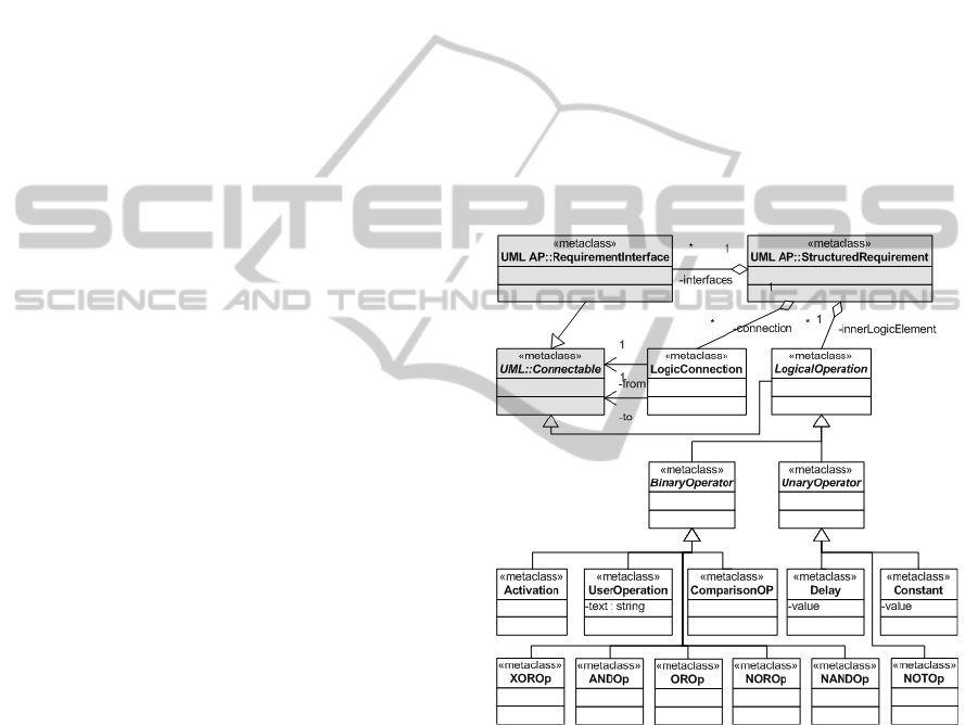
presented in figure 1. Existing UML AP and UML
metamodel elements are highlighted with grey
colour.
Figure 1: The essential additions to UML AP metamodel
to support the definition of interlocks.
In UML AP, requirements are structured
concepts that can be connected to others with port-
like interfaces in order to model dependencies
between required functions. The purpose of the logic
concepts, on the other hand, is to enable the
modelling of required activations of interlocks and
algorithms to compute control values. Required
interchange of computed signals and values can then
be modelled with the interfaces. The operations
include familiar operations, such as AND and OR,
but also delay, constant, Activation gate (that lets its
input flow to output when control input is activated),
SIMULATION ASSISTED, MODEL-BASED DEVELOPMENT OF SAFETY RELATED INTERLOCKS
269
comparison operator and a UserOperation with
which the developer can specify the logic to output
from inputs with a textual equation. Examples of use
of the concepts will be provided in section 5.
The functional modelling concepts of UML AP,
Automation Functions, constitute a hierarchy of
function-block-like concepts. The hierarchy is based
on their purpose, such as to execute control
algorithms or to interface with sensors or actuators
of the system. They are presented in detail in
(Hästbacka et al. 2011). Automation Functions
(AFs) exchange signals between them with ports that
extend the UML::Connectable concept (see figure
1). The logic operators and connections, on the other
hand, can be used inside the AFs to define the
functionality of them. Consequently, the technical
challenges of our approach to simulate the models
are in transforming the specifications conforming to
UML AP to simulation models. The solution to
transform the models to ModelicaML models and
finally to simulateable Modelica models will be
discussed in next section.
4 IMPLEMENTATION
OF THE APPROACH
It is first necessary to present some basic
information about Modelica and ModelicaML that
are used in our approach as target simulation
languages. Modelica is an object oriented simulation
language for modelling of large, complex and
heterogeneous physical systems. Modelica models
are mathematically described by differential,
algebraic and discrete equations. Modelica includes
also a graphical notation and user models are usually
described by schematics that are also called object
diagrams. A schematic consists of components,
which are connected together using connectors
(ports) and connections. A component, on the other
hand, can be defined by another schematic or, on the
lowest level, as a textual equation based definition.
Modelica Modeling Language (ModelicaML),
on the other hand, has been created to enable an
efficient way to create, read, understand and
maintain Modelica models with UML tools
(Schamai 2009). ModelicaML is a UML profile and
defines stereotypes and tagged values of stereotypes
that correspond to the keywords and concepts of the
textual Modelica language. ModelicaML models are
not simulateable as they are (at least with current
tool support) but can be transformed to simulateable
Modelica models. Tool support for generating
textual Modelica models, as well as the profile, is
made publicly available by the OpenModelica
project. (OpenModelica 2011) The profile is based
on UML2 implementation of the UML metamodel
on the Eclipse platform. UML2 is further based on
Eclipse Modeling Framework (EMF) which is an
implementation of OMG MOF specification on the
platform.
EMF is also utilized by our UML AP metamodel
implementation (Vepsäläinen et al. 2008). Because
of this similar background, the shifting between
UML AP and ModelicaML can be realized with use
of standardized QVT languages. The possibility to
use standardized transformation languages with
existing open source tool support and the open
source background of Modelica and ModelicaML
are good reasons for selecting Modelica as the target
simulation language in our approach.
In Modelica (and in ModelicaML) simulation
classes are defined separately from their use context,
similarly to classes in object oriented programming
languages. In ModelicaML models, the model
elements also need to reference the ModelicaML
profile in order to use the stereotypes and tagged
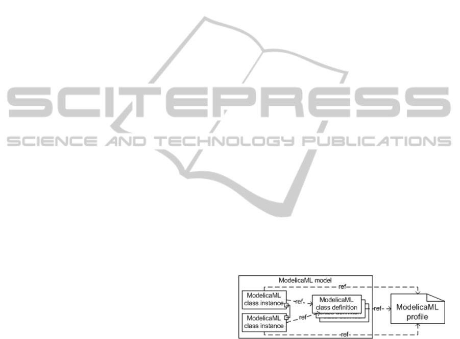
values of it. This results in a structure sketched in
figure 2. ModelicaML models consist of Modelica
class definitions and instances of the classes. Classes
may contain ports with which they can be connected
and both the definitions and instances of the classes
need to use the stereotypes of the ModelicaML
profile in order to map the concepts to Modelica
keywords. In our approach, we assume that
ModelicaML models of processes to be controlled
are available and conform to this structure.
Figure 2: General structure of ModelicaML models.
The purpose of the transformation is to add the
control system specific parts to the existing model of
the process to be controlled and to connect the parts
to the existing model so that the controlled system
can be simulated. In this process, the transformation
utilizes librarized ModelicaML classes for platform
independent (PIM) and platform specific (PSM)
concepts. Librarized definitions are copied to the
model and instances of them are created and
connected together and to the existing model
elements according to the UML AP model. This
process is discussed in detail in (Vepsäläinen at al.
2010a). However, because interlocks are specific to
SIMULTECH 2011 - 1st International Conference on Simulation and Modeling Methodologies, Technologies and
Applications
270
applications they cannot be librarized, as explained
earlier.
Instead, the definitions of interlock classes need
to be created by the transformation based on the
logic diagrams. This process is rather simple and
illustrated with an example shown in figure 3. Ports
contained by classes, such as interlocks, are special
kind of classes in Modelica and finally typed by type
definitions in ModelicaML profile. When creating
ModelicaML classes based on UML AP classes,
instances of such special port classes can be created
and named based on ports used in the UML AP
model. This applies to both input and output ports.
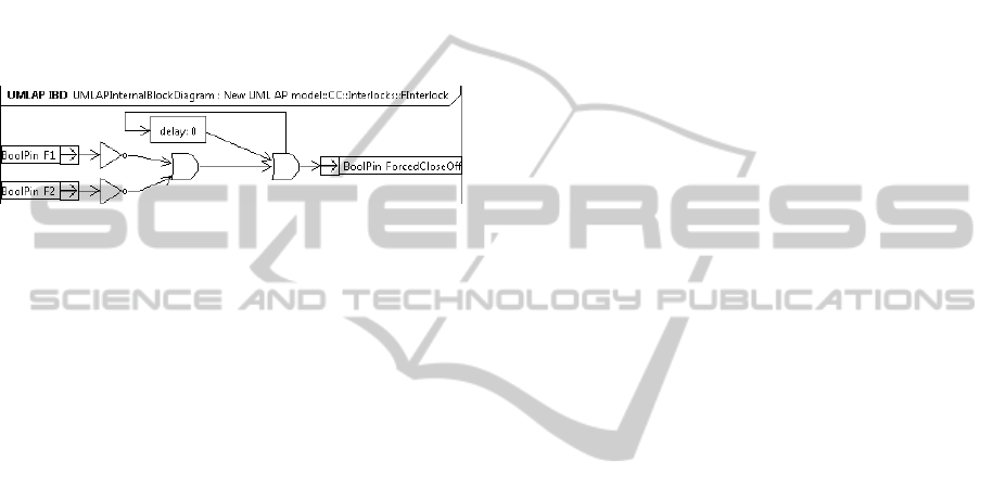
Figure 3: Simple example of an interlocking function.
Figure 3 contains only three kinds of logical
operations of the 11 presented in figure 1: two NOT
and two OR operations and one delay. The
transformation processes operations by creating a
property (variable) for each operation instance. In
case of Boolean operations (NOT, AND, NAND,
OR, NOR, XOR, the type of the property is always
Boolean. In case of other operations, the type needs
to be defined in the UML AP model so that the
corresponding ModelicaML type can be chosen. The
equations determining the values of the properties
are created based on the kind (for example NOT or
AND) and the connections coming into the operation
which can be followed to another operation or port.
For example, the value of the first OR operation
(from left in figure 3) can be defined equal to the
logical OR of the values of the NOT operations.
The transformation, thus, tries to define the
values of properties with equations. However, if a
model contains loops, this may not be possible. For
example figure 3 contains a loop the purpose of
which is to keep the interlock activated if it once
activates so that the output of the second OR
operation (from left) is true. Certain kinds of loops
may produce errors, at least with the OpenModelica
tool that we use for simulating, so the problem was
solved by using algorithms in which operations are
applied in an order (instead of equations that apply
all the time). This is also one of the interactive
features of our transformation. If the transformation
detects a loop within an interlock or other kind of
AF, it creates algorithmic statements based on the
model, shows them to the user of the tool and lets
the user select the order in which they are executed.
Another interactive feature of the transformation
is related to connecting model parts of the control
system to parts of the process to be controlled. These
connections are necessary for, for example,
connecting measurement functions of control
systems to sensors of the process models. By
default, the transformation uses properties of the
process model with specific names or the names of
properties that have been specified with a specific
VariableMapping stereotype. However, if suitable
properties are not found, the transformation provides
the user of the tool with a list of properties available
in the model class in question and lets the user to
choose the correct property.
The third interactive feature is related to un-
connected ports. When an unconnected input port is
detected by the transformation, the user of the tool is
asked for a constant value for the port. In this case,
the user of the tool may leave the port unconnected
or define a constant value for it in order to be able to
simulate the design. If the port has been left un-
connected unintentionally, the user may fix the
problem before executing the transformation again.
The transformation definition was written with
QVT operational mappings language and it specifies
how to process target models based on source
models. Executable Java-transformation code to be
used in the Eclipse environment was generated with
SmartQVT tooling. In order to be able to implement,
for example, the interactive features, the generated
transformation class was extended with a hand-
written Java class that also handles the processing of
tagged values related to stereotypes. In order to be
able to launch and control the transformation from
the UML AP tool, the transformation was packaged
to a plugin defining an (Eclipse) extension to one of
the extension points of the tool. The structure of the
plugin was similar to the plugin structure presented
in (Vepsäläinen et al. 2009). The referred paper also
presents in detail the extension points of the tool.
5 EXAMPLE CASE
The purpose of this section is to provide a simple
example in which the modelling concepts and tools
are used in creation of a simulation model of a
controlled process to evaluate two alternative
interlocking approaches.
An illustration of the (partial) system to be
controlled is shown in figure 4. The system consists
of a cart and a rail along which the cart can be
moved with an electric motor. The cart can be
stopped with a brake, if necessary. The purpose of
SIMULATION ASSISTED, MODEL-BASED DEVELOPMENT OF SAFETY RELATED INTERLOCKS
271
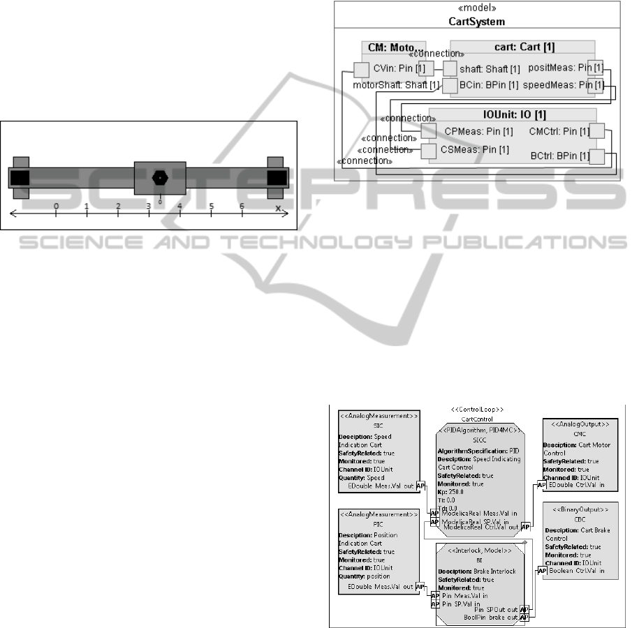
the cart is left unspecified and not illustrated in the
figure. It could be assumed, for example, to operate
a boom or a gripping device nearby the rail. The
control needs to be addressed in the example are
related to only controlling the velocity and location
of the cart. The operator of the system controls the
system by giving speed requests (setpoints) with a
joystick. In addition to feedback control of the cart
speed, the control system is supposed to protect the
cart from colliding to stoppers at the end of the rail.
In detail, the location of the cart must be kept
between 0.0 and 6.0. In industrial installations the
need for a similar stopping interlock could be also
caused by forbidden areas.
Figure 4: Simple example system to be controlled includes
a cart that can be moved along a rail.
The stopping functionality can be implemented
with at least two alternative approaches. Firstly, the
control system could observe the location and
direction of the cart and stop it with the brake, if the
cart violates the limits. Secondly, the control system
could be designed to constrain the speed setpoint
near the limits so that the setpoint would be zero at
the limit coordinates and it would be reduced
already before reaching the limits. These approaches
will be next simulated based on a ModelicaML
model of the process to be controlled and UML AP
models of the control approaches.
To be able to utilize the tools and techniques
presented in this paper, the system to be controlled
need to be available as a ModelicaML model. The
UML composite diagram presenting the simplified
model of the system is in figure 5. The model
consists of 3 ModelicaML components that are
instances of ModelicaML classes. The cart is
operated with a motor (CM) that takes its control
signal from the IOUnit that collects all measurement
and control signals. The total weight of the cart and
motor is assumed to be 20kg (m
total
) and the radius
of the drive wheel 0.1m (r
dw
). The torque (T) and
acceleration (a) equations of the motor and cart
based on drive voltage (V
d
) are presented in
equations 1, 2 and 3. The numerical values of the
constants of the motor are: R
m
=0.5, L
m
=0.0015,
K
emf
=0.05 and K
t
=0.01. The brake is assumed to be
able to decelerate the cart with force of 200N (F
b
).
The equations are, thus, simple but sufficient for
demonstration purposes.
V
d
– ω * K
em
f
= L
m
* dI/dt + R
m
*I (1)
T = K
t
*I (2)
T / r
dw
+ F
b
= m
tota
l
* a (3)
Figure 5: Model of the system to be controlled as a
ModelicaML model, composite structure diagram.
The UML AP control structure diagram
presenting a control solution for the system is
depicted in figure 6. The control solution consists of
analogue measurements of cart position and speed,
an interlock, a PID controller and a binary and an
analogue output for controlling the brake and the
motor, respectively. In the first solution, the speed
request (setpoint) is not constrained. However, in
order to enable that to be implemented later, the
speed request is relayed through the interlock AF.
Figure 6: UML AP control structure diagram of a control
solution for controlling the process.
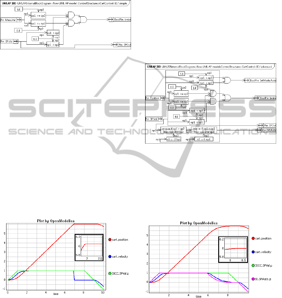
The detailed logic of the first interlocking
solution is presented in figure 7. The solution is
designed to activate the brake outside the intended
working area if the speed request is driving the cart
away from the working area. In order to be able to
SIMULTECH 2011 - 1st International Conference on Simulation and Modeling Methodologies, Technologies and
Applications
272
revert back to the working area, the brake is not
activated if the speed request is towards the allowed
working area.
Figure 7: An illustration of the first interlocking solution.
After specification of the detailed control
solution, the transformation, discussed in section 4,
was used to transform the UML AP control solution
to ModelicaML and to append it to the existing
model of the physical process (see figure 5). In order
to simulate the model, the ModelicaML model was
further transformed to Modelica code with
OpenModelica tooling. The shifting from UML AP
model to simulateable model was, thus, totally
automated with two model transformations.
The simulation result related to the solution is
presented in figure 8. At the beginning, the position
of the cart is 0 as is also its speed. The speed request
is ramped from 0 to 1 and kept at 1 for 7 seconds
after which, the speed request is ramped to -1 in
order to revert the cart. The control solution works
as it was intended, however, because it takes time to
stop the cart, the location of the cart reaches 6.05
before stopping. Clearly, the control solution could
be improved by decelerating the cart already before
reaching the limits.
Figure 8: Simulation result of the first control solution
plotting cart position (cart.position), velocity
(cart.velocity) and speed request (SICC.SPVal.p).
The second control solution is illustrated in
figure 9. In this solution, the braking is implemented
similarly to the first solution and the speed request
from the user is relayed similarly to the controller.
However, when the measured location of the cart is
between 0 and 1 or between 5 and 6, an automatic
mode is activated and another speed setpoint is
calculated by the interlock function. The setpoint is
constrained so that between 0 and 1 and between 5
and 6, the maximum allowable speed setpoint is
equal to the distance left to the limit. For example, if
the location is 5.5, the maximum allowed speed
setpoint is 0.5 to the positive direction. In order to
relay the second setpoint signal and the mode
activation signal, the AF block has been added two
new ports. Similar ports were added also to the
controller block (see figure 6) and its equations.
Figure 9: The second interlocking solution.
The simulation result related to the improved
interlocking function is presented in figure 10. The
speed request obtained from the user is similar to
that of the first simulation. In this case, the cart is
smoothly decelerated already before reaching the
limit and the overshoot is much smaller than that in
the first simulation. Clearly, this alternative provides
a better control performance.
Figure 10: Simulation result of the second control solution
plotting cart position, velocity, speed request and
constrained speed request (BI.SPAuto.p).
SIMULATION ASSISTED, MODEL-BASED DEVELOPMENT OF SAFETY RELATED INTERLOCKS
273

6 TOWARDS DEVELOPMENT
OF SAFETY FUNCTIONS
The use of model-based techniques in development
of safety-critical applications has not been
recommended by safety standards, such as IEC
61508, until recently. However, due to the new
version of the standard, they could be used to, for
example, aid testing and architecture design.
Perhaps the most essential difference between
the development of safety systems and basic control
systems is that safety systems require extensive
documentation including clear and unambiguous
specification of requirements and design. We are
currently striving to extend the scope of UML AP to
cover also the development and design of safety
systems. The work is targeted to the requirement
concepts of the profile (see Hästbacka et al. 2011)
but also to documentation of the results of risk and
hazard analysis so that the models could also
document the traceability between them and
software development. Another working direction is
the ability to simulate designs and specifications.
Testing or simulation-aided testing of design and
development specifications cannot be used to prove
the correctness of them. However, simulations can
be used to test the reactions of control or safety
systems to events in the system that could not be
tested with the actual system without compromising
safety. Extensive testing is also required by
standards. The problem with conventional testing is
that the system should be already implemented in
order to be tested. With our approach, the main
improvement is the ability to test earlier in the
development process.
Another difficulty in development of both safety
and basic control systems is related to the
specification of requirements. In development of
safety-critical applications, the functional
requirements (what the system must do) originate
from hazard analysis and the non-functional
requirements (how well it must be done) from risk
analysis. However, unambiguous and complete
specification of the functional requirements is still
difficult. Perhaps this task could be easier with a
semi-formal, domain specific modelling approach.
In (Jones 2008) the author has analysed the
quality of produced software in about 12500 projects
from year 1984 to 2008 and the defects delivered
(and removed) during the projects. The results may
not be directly generalizable to safety-critical
applications, however, according to the survey, also
in the best-in-class-quality, a main portion of defects
delivered were related to defects in requirements
specifications, partly because defects in
requirements are difficult to discover.
If the design could be simulated earlier, for
example with the techniques presented, simulations
could be also used to assess whether the required
functionality is able to detect and handle the
hazardous situations. The feedback loop from design
to requirements could thus be shortened. This could
further facilitate the development of both basic
control and safety-systems.
7 CONCLUSIONS
This paper has presented a tool-supported approach
to transform functional UML AP models and their
interlocking specifications to ModelicaML models
and finally to simulateable Modelica models. The
aim of the transformation is to enable automated and
less tedious creation of simulation models and thus
support model-driven development of control
systems, including their interlocking and constraint
control functions. Compared to present development
practices of control systems, this could enable the
testing of the solutions earlier during the
development process. The approach also offers the
other benefits of simulations.
The example system and the control approaches
presented in this paper were both simple but still
adequate for demonstrating the techniques in
creation of two simulation models. Simulations
could then be used to compare the two interlocking
approaches. This is also how simulations are
currently typically used if their development is
considered worthwhile.
Simulations can facilitate the analysis of systems
– not directly the synthesis of systems. Nevertheless,
simulations can still help developers in making
design decisions. The purpose of model-based
techniques is often to automate simple development
tasks. However, also within model-based
development, real design decisions need to be made
by developers and this work can be eased with
simulations. In our approach, we use model-based
techniques also for developing the simulation
models. We thus aim to facilitate model-based
development of control systems by application of
more model-based techniques.
A future working direction of our approach is to
shift towards safety functions which share several
similarities with interlocks. It is clear that also
development of safety functions could benefit from
simulations. However, the development of safety
related systems requires extensive documentation of
SIMULTECH 2011 - 1st International Conference on Simulation and Modeling Methodologies, Technologies and
Applications
274

design and traceability between design artefacts.
This is why we are currently working with the
requirement sub-profile of UML AP. With this
work, we aim to support the detailed definition of
requirements but also documentation of information
originating from risk and hazard analysis phases.
The rationale is that the requirements of safety
functions are based on these analyses but the
information is not always visible for, for example,
the software developers, which makes it difficult to
judge the correctness and completeness of design.
REFERENCES
Biehl, M., DeJiu, C. and Törngren, M. 2010 “Integrating
safety analysis into the model-based development
toolchain of automotive embedded systems”. In:
LCTES 2010, pp 125-132, New York, NY, USA,
2010. ACM.
Carrasco, J. and Dormido, S. “Analysis of the use of
industrial control systems in simulators: State of the
art and basic guidelines”. 2006. ISA Transactions, Vol
45, Number 2, April 2006, pp. 295–312
Dougall, J. Applications and benefits of real-time I/0
simulation for PLC and PC control systems. 1998. ISA
Transactions, Vol. 36. No. 4. 1998, pp. 305-311.
Ferrarini, L., Dede, A., Salaun, P., Tuan Dang, Fogliazza,
G. 2009. “Domain specific views in model-driven
embedded systems design in industrial automation”.
INDIN 2009 the 7th IEEE International Conference on
Industrial Informatics, June 23-26, 2009, Cardiff, UK.
Friedenthal, S., Moore, A., Steiner, R. 2008 “A practical
guide to SysML”. Morgan Kaufmann OMG Press, San
Francisco. 2008
Hästbacka, D., Vepsäläinen, T., Kuikka, S. 2011. Model-
driven Development of Industrial Process Control
Applications, The Journal of Systems and Software
(2011), In Press, Accepted Manuscript, doi:10.
1016/j.jss.2011.01.063
IEC 61508: Functional safety of electrical/electronic/
programmable electronic safety-related systems. parts
1-7. 2010
Jones, C. 2008. “Software quality in 2008: A survey of the
state of the art”. Software Productivity Research LLC.
http://www.jasst.jp/archives/jasst08e/pdf/A1.pdf
(achieved 13.2.2011). 59 p.
Karhela, T. 2002. “A software architecture for
configuration and usage of process simulation models:
Software component technology and XML-based
approach” PhD Thesis, VTT Technical Research
Centre, Finland.
Object Management Group. 2003. Technical Guide to
Model Driven Architecture: The MDA Guide. Version
1.0.1 (formal/2008-04-03) Edition.
OpenModelica project website. 2011. http://www.ida.liu.
se/pelab/modelica/OpenModelica.html
Ritala, T., Kuikka, S. 2007. “UML Automation Profile:
Enhancing the Efficiency of Software Development in
the Automation Industry”, The Proceedings of the 5th
IEEE International Conference on Industrial
Informatics (INDIN 2007), Vienna, Austria, July 23-
27, 2007, pp. 885-890.
Schamai, W. 2009. “Modelica Modeling Language
(ModelicaML) – a UML Profile for Modelica”,
Technical Report 2009:5, EADS IW, Germany,
Linköping University, Institute of Technology.
Strasser, T., Rooker, M., Ebenhofer, G. 2009a. “MEDEIA
- Model-Driven Embedded Systems Design
Environment for the Industrial Automation Sector”.
1st Version of the MEDEIA open source modelling
prototype (documentation). Available: http://www.
medeia. eu/26.0.html
Strasser, T., Rooker, M., Hegny, I., Wenger, M., Zoitl, A.,
Ferrarini, L.,Dede, A., Colla, M. 2009b. “A research
roadmap for model-driven design of embedded
systems for automation components”. INDIN 2009 the
7th IEEE International Conference on Industrial
Informatics, June 23-26, 2009, Cardiff, UK.
Tranoris, C., Thramboulidis, C. 2006. “A tool supported
engineering process for developing control
applications”. Computers in Industry, Vol. 57, pp.
462-472, 2006.
Vepsäläinen, T., Hästbacka, D., Kuikka, S. 2008. “Tool
Support for the UML Automation Profile - for
Domain-Specific Software Development in
Manufacturing”, The Proceedings of the 3rd
International Conference on Software Engineering
Advances, Sliema, Malta, October 26-31 2008. pp. 43-
50.
Vepsäläinen, T., Hästbacka D. and Kuikka, S. 2009. ”A
Model-driven Tool Environment for Automation and
Control Application Development - Transformation
Assisted, Extendable Approach”. In Proceedings of
the 7th Nordic Workshop on Model Driven Software
Engineering, Tampere, Finland, August 26-28, 2009.
Vepsäläinen, T., Hästbacka, D., Kuikka S., 2010a.
"Simulation Assisted Model-Based Control
Development - Unifying UML AP and Modelica ML",
in 11th International Middle Eastern Simulation
Multiconference, Alexandria, Egypt, December 1-3,
2010a.
Vepsäläinen, T., Sierla, S., Peltola, J and Kuikka, S.,
2010b. ”Assessing the Industrial Applicability and
Adoption Potential of the AUKOTON Model Driven
Control Application Engineering Approach”,
Proceedings of International Conference on Industrial
Informatics. Osaka, Japan, July 13-16, 2010b.
Zoughbi, G., Briand, L., Labiche, Y. 2007. “A UML
Profile for Developing Airworthiness-Compliant
(RTCA DO-178B), Safety-Critical Software”. In:
MODELS 2007. LNCS, vol. 4735, pp. 574–588.
Springer, Heidelberg (2007)
SIMULATION ASSISTED, MODEL-BASED DEVELOPMENT OF SAFETY RELATED INTERLOCKS
275
