
MECHATRONIC SYSTEM MODELING
A Consistent Preliminary Design Process
Jean-Yves Choley, Régis Plateaux, Olivia Penas
SUPMECA (LISMMA Laboratory), 3 Rue F. Hainaut, 93407 Saint Ouen Cedex, France
Christophe Combastel
ENSEA (ECS laboratory), 6 Avenue du Ponceau, 95014 Cergy-Pontoise Cedex, France
Hubert Kadima
EISTI (LARIS laboratory), Avenue du Parc, 95011 Cergy-Pontoise Cedex, France
Keywords: Preliminary design, Mechatronic system, Modelling, Topology, Interval analysis.
Abstract: In order to describe a consistent and collaborative preliminary design process for mechatronic systems, this
study deals with an automotive power lift gate scenario. First, a functional analysis is carried out with
SysML from user requirements. This allows one to define suitable architectures and associated test cases.
Each of them has to be analysed and optimized separately in order to select the best architecture and the best
set of key parameters. The next step of the preliminary design is a modelling of its structure and its
behaviour. In order to merge multi-physical and geometrical parameters, our generic method relies on a
topological analysis of the system and generates a set of equations with physical and topological constraints
previously defined. Finally, an interval analysis is implemented, allowing one to explore exhaustively the
search space resulting from a declarative statement of constraints, in order to optimize the parameters under
the constraint of the relevant test cases.
1 INTRODUCTION
Nowadays, system engineering problems are solved
using a wide range of domain-specific modelling
languages and tools. Standards such as ISO 15288
detail the large number of system aspects and
various components of multi-domain systems
(ISO/IEC 2001) (Turki, 2008). It is also not realistic
to create an all-encompassing systems engineering
language capable of modelling and simulating every
aspect of a system. However, for multi-domain
systems, a global approach is necessary. Indeed,
each domain has its own methodologies and
languages, thus impeding the consistency of the
different modelling. Hence, a global optimization is
difficult during the preliminary design process of
these systems.
Mechatronic systems development involve
considering the modelling of their components
together with their interactions. Models can be used
to formally represent all aspects of a systems
engineering problem, including requirements,
functional, structural, and behavioural modelling.
Additionally, simulations can be performed on these
models in order to verify and validate the
effectiveness of design decisions.
This study covers the preliminary design phase
of a mechatronic system, in order to verify that the
chosen design is in accordance with the system
requirements and to verify that this chosen design
minimizes risks in further design phases. Following
the recent advances in Model Based System
Engineering (Estefan, 2008), the preliminary design
can be viewed as a model transformation process
(Hartman and Kreische, 2005).
Based on the example of a power lift gate, our
goal is to show how the engineering knowledge can
be formalized and used all along the three following
phases of the preliminary design process:
requirements definition and functional analysis,
geometrical and physical modelling, optimization.
Once the early design phases have been
performed with SysML models, the physical
modelling of the overall system has to be built,
based on the topology of the system, in order to
generate the equations required for the optimization
57
Choley J., Plateaux R., Penas O., Combastel C. and Kadima H..
MECHATRONIC SYSTEM MODELING - A Consistent Preliminary Design Process.
DOI: 10.5220/0003598800570064
In Proceedings of 1st International Conference on Simulation and Modeling Methodologies, Technologies and Applications (SIMULTECH-2011), pages
57-64
ISBN: 978-989-8425-78-2
Copyright
c
2011 SCITEPRESS (Science and Technology Publications, Lda.)
phase. This being done, the Design Space
Exploration can be executed in order to discover the
optimal design solution from all functional and
architectural specifications and constraints. Indeed,
the most efficient way to explore this design space is
to reason about previous SysML models, thus
proving in a mathematically rigorous way that all
required properties and constraints are met.
2 A POWER LIFT GATE
SCENARIO
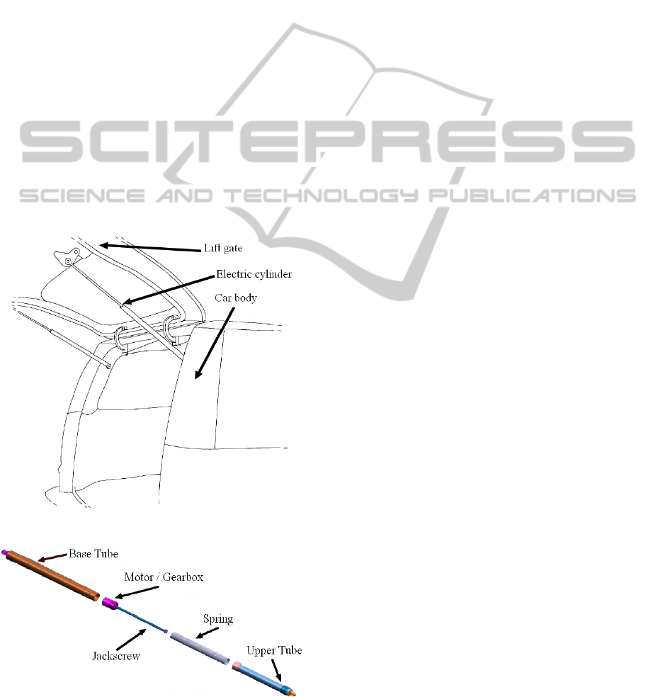
An automotive power lift gate (Figure 1) includes a
lift gate door hinged to a car body. This system
moves the lift gate between its open and closed
positions, thanks to electric cylinders (Figure 2) that
replace the usual gas struts in a classic manual lift
gate. It includes a motor and a gearbox that are fixed
to the base tube and a jackscrew that drives the
upper tube, helped by a spring, in order to sustain
static forces. Both electric cylinders are identical and
are fixed to the car body and the lift gate.
Figure 1: The Power Lift Gate Location on a Car Body.
Figure 2: The Electric Cylinder Architecture.
In order to ensure that the main requirements are
fulfilled, such as the opening duration and the power
consumption, the electric cylinder has to be
preliminarily designed, whatever its internal
structure is, meaning that the fixing points on the
car-body and the lift gate, the force needed to open
and maintain the lift gate and its full length and rest
length have to be determined.
3 THE PRELIMINARY DESIGN
PROCESS
The proposed preliminary design process relies on a
methodology that deals with different modelling,
(SysML model, topological model) in order to
provide consistent equations for an optimisation of
the mechatronic system with interval analysis.
3.1 Modelling of the Power Lift Gate
System with SysML
We propose a modelling of a power lift gate system
by means of appropriate SysML models at the early
stages of the technical engineering process. The
different SysML diagrams make it possible for
engineers from various disciplinary fields to share a
common view about the system. First, we create an
extended context diagram, in order to present the
different interactions between the extended system
(Lift gate + Electric cylinder) and its environment
(Figure 3).
Then a Use Case Diagram is defined to describe
the system services (Figure 4).
SysML Requirement Diagram can be used to
clearly organize user and derived system
requirements (Figure 5). By using a hierarchical
representation of the requirements, clear gains can
be made in the elaboration of requirements, in
tradeoffs, as well as in the validation and the
verification of requirements. Indeed, during design
activities, verification activities need to be defined to
satisfy system constraints and properties. Links
between the Requirements Diagram and other
models allow engineers to connect test criteria to test
cases used throughout the development process.
During the architecture analysis, system synthesis by
assigning functions to identified physical
architecture elements (subsystems, components) is
carried out (Figure 6). Finally we create a kinematic
joint diagram (Figure 7) with connectors regarding
to application points and with links representing the
field or the type of joints between two elements.
SIMULTECH 2011 - 1st International Conference on Simulation and Modeling Methodologies, Technologies and
Applications
58
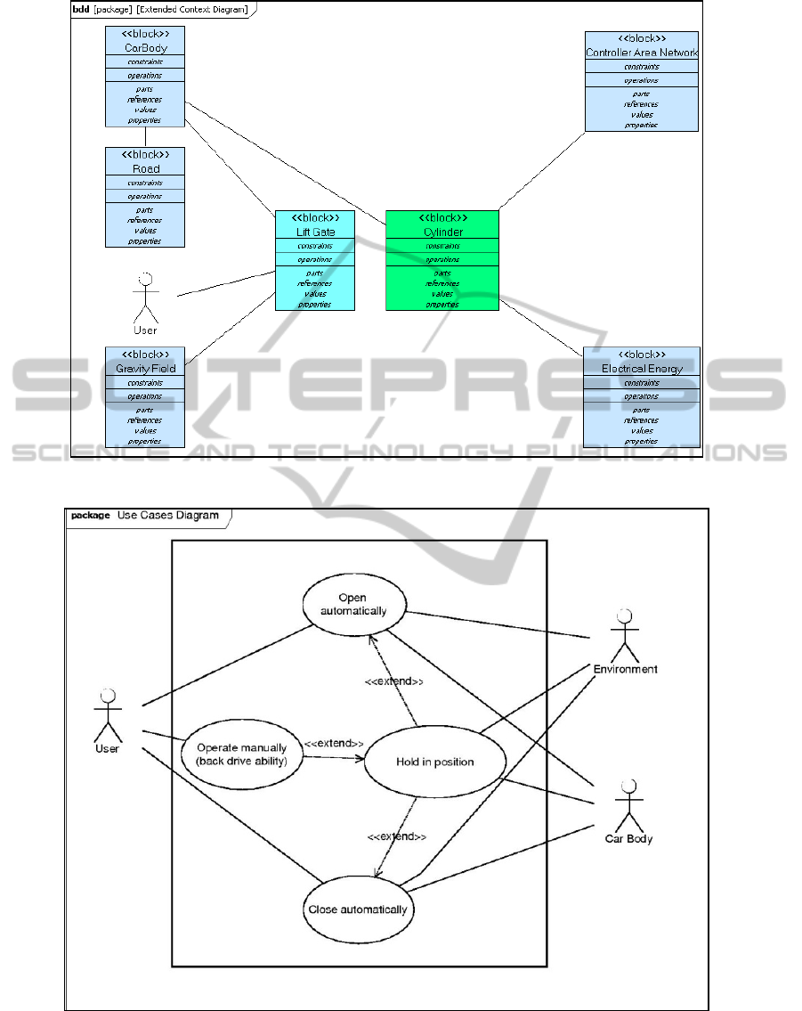
Figure 3: Extended Context Diagram of the Power Lift Gate System.
Figure 4: Use Cases Diagram of the Power Lift Gate System.
MECHATRONIC SYSTEM MODELING - A Consistent Preliminary Design Process
59
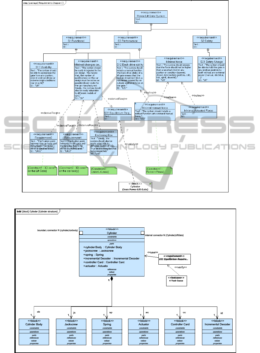
Figure 5: Requirements Diagram.
Figure 6: Architecture, Test Cases and System Requirements Attachment.
SIMULTECH 2011 - 1st International Conference on Simulation and Modeling Methodologies, Technologies and
Applications
60
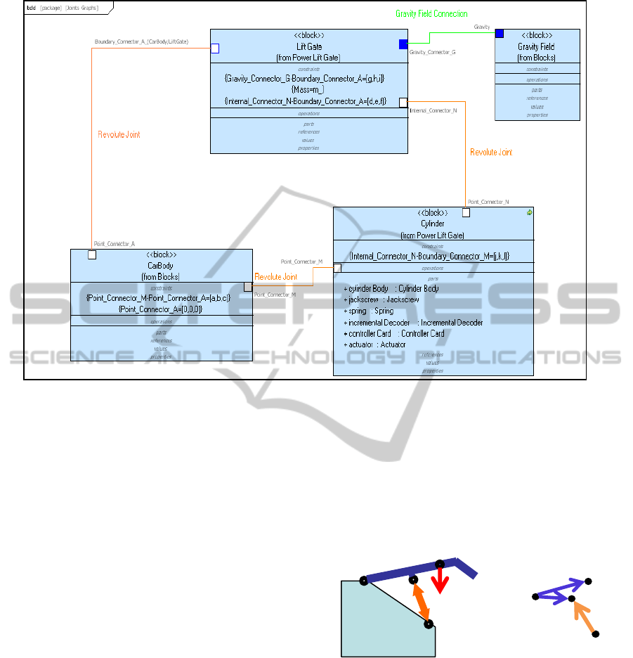
Figure 7: Kinematic Joints Relations Diagram in SysML.
3.2 Vector-based Mechanical
Modelling Derived from System
Topology
The previous SysML diagrams bring to light the key
parameters and the topology of the power lift gate
system. In order to optimize these key parameters,
this mechanical problem has to be translated into
equations. We propose to use a highly suitable
method (Plateaux et al, 2008) for multi-domain
systems such as automotive mechatronic
components. Based on a topological analysis of the
system, this generic method delivers equations that
can be processed by a solver. It relies on the works
of Kron (Kron, 1959), Branin (Branin, 1966) and
Björke (Björke, 1995). Here, our method is
restrained to the mechanical study of the static
equilibrium of the lift gate but it may also be used to
express the internal structure of the electric cylinder
(screw and nut system, tubes, gearbox, spring,
sensors, electrical engine and electronic
components...).
The isolated system includes the lift gate with the
electric cylinder between the points M and N, the car
body being an external system. Let us assume that:
the mechanical joints are perfect; points A, M and G
belong to the system boundary; there is neither
external mechanical force nor torque on internal
point N; P is the external force on the gravity centre
G; F
C
is the force created by the electrical cylinder,
which corresponds to the internal force R
MN
.
In order to model the architecture of the system,
a topological graph has first to be defined from
geometrical and mechanical definitions of the
problem (figure 8).
M
A
G
N
P=mg
M
A
N
G
Figure 8: Power Lift Gate Topological Graph.
We use the kinematic joints diagram and the
vectorial constraints between characteristic points of
previous SysML diagrams to describe the
topological structure. Indeed, each connector in the
kinematic joints relations diagram represent a
particular point, named “node” in the topological
structure, and each link between two connectors give
the nature of the kinematic screw, dual of its static
screw. The automation of this process between
SysML diagrams and our topological representation
is made through the analysis of a xml/xmi generated
MECHATRONIC SYSTEM MODELING - A Consistent Preliminary Design Process
61
file from the SysML Kinematic Joints Relations
Diagram (Figure 7). So, the boundary of the system
is expressed by means of labels attached to each
node (boundary) named (A, G, ...), like the SysML
connectors, and to each branch (internal), all of them
inherited from SysML diagrams.
Then, the topology has to be mathematically
expressed (equation 1) using a connexion (or
incidence) matrix named C and an algebraic graph
that allows one to connect nodes and branches. The
topological structure (graph) is overlaid with an
algebraic structure. This global structure connects
nodes and branches of the graph, and may include
physical parameters which govern the behaviour of
the system. This method has been thoroughly
described in previous papers (Plateaux et al, 2007)
(Plateaux et al, 2008).
A
M
N
G
⎛⎞
⎜⎟
⎜⎟
⎜⎟
⎜⎟
⎝⎠
AN
MN
AG
⎛⎞
⎜⎟
⎜⎟
⎜⎟
⎝⎠
1010
C=(-1) 0 1 1 0
1001
−
⎡⎤
⎢⎥
−
⎢⎥
⎢⎥
−
⎣⎦
Branches
(internal)
Nodes
(external)
(1)
Thus, the transposed matrix C
T
can be used to
express (equation 2) the connection between internal
and external mechanical forces and moments,
defined with their associated static screws, with T
A
standing for “screw of external mechanical action on
point A” and T
AN
standing for “screw of internal
mechanical action on AN structure”:
AN
MN
AG
T
T
T
⎛⎞
⎜⎟
⎜⎟
⎜⎟
⎝⎠
AANAG
MMN
NANMN
GAG
TTT
TT
TTT
TT
+
⎛⎞⎛
⎞
⎜⎟⎜
⎟
⎜⎟⎜
⎟
=
⎜⎟⎜
⎟
−−
⎜⎟⎜
⎟
−
⎝⎠⎝
⎠
T
10 1
010
C=(-1)
110
001
−−
⎡⎤
⎢⎥
−
⎢⎥
⎢⎥
⎢⎥
⎣⎦
(2)
As a result, an equations system (3) is obtained, with
the decomposition of screws in 4 force equations
and in 4 moment equations expressed in the
arbitrarily chosen point A:
A
A
A
AN
AN
MN
MN
AG
AG
R
M
R
M
R
M
⎛⎞
⎧⎫
⎜⎟
⎨⎬
⎩⎭
⎜⎟
⎜⎟
⎧⎫
⎜⎟
⎨⎬
⎜⎟
⎩⎭
⎜⎟
⎧⎫
⎜⎟
⎨⎬
⎜⎟
⎩⎭
⎝⎠
A
AANAG
MMN
NANMN
GAG
AANAG
MMN
NANMN
GAG
R=R R
R=R
R=R R
R=R
M=M M
M=M
M=M M
M=M
+
⎧⎫
⎪⎪
⎪⎪
⎪⎪
−−
⎪⎪
−
⎪⎪
⎨⎬
+
⎪⎪
⎪⎪
⎪⎪
−−
⎪⎪
⎪⎪
−
⎩⎭
T
10 1
010
C=(-1)
110
001
−−
⎡⎤
⎢⎥
−
⎢⎥
⎢⎥
⎢⎥
⎣⎦
(3)
The equations system is solved and the static
equilibrium of the lift gate system is expressed.
3.3 Computational Support for the
Exploration of the Solution Space
based on Constraint Programming
and Interval Analysis
Special emphasis is also placed on interval-based
computational methods (Jaulin et al, 2001) allowing
one to explore exhaustively the search space
resulting from a declarative statement of constraints
(Yannou et al, 2003). Given the previous high level
vector model linked to a given topology, formal
calculus and causal ordering based on bipartite
graphs theory (Duff, 1981) (Pothen and Chin-Ju,
1990) can be used to avoid part of the tedious work
consisting in giving the mathematical expressions of
some constraints as required to run dedicated
solvers. The use of interval computations within a
constraint programming paradigm (Blick et al, 2001)
also provides a computational support to quantify
uncertainties and to detect inconsistencies. From a
methodological point of view, the refinement
inherent to the design process is underlined.
A Constraint Satisfaction Problem (CSP) is
usually defined by (X, D, C) where X = {x
1
, x
2
, …,
x
n
} is a set of variables, D = {d
1
, d
2
, …, d
n
} is a set of
domains such that
∀
i
∈
{1,…, n}, xi
∈
di, and C =
{C1, …, Cm} is a set of constraints depending on the
variables in X. Each constraint includes information
related to constraining the values for one or more
variables. When continuous variables are
considered, the use of interval analysis techniques
naturally arises in order to represent the domains.
Those methods make it possible to explicitly take
uncertainties (in the sense of deterministic
imprecision rather than probabilistic variability) into
account in the preliminary design process. The use
of an interval CSP solver (here, RealPaver)
(Granvilliers, 2003) allows an exhaustive search
within the search space D which is partitioned into
three sets, D = D
0
∪
D
1
∪
D
?
, the latter two being
described by a box paving: D
0
is a sub-domains of D
where the constraints are never satisfied; D
1
is a sub-
domains of D where the constraints are always
satisfied; D
?
is a sub-domains of D where the
satisfiability of the constraints has not been decided
yet according to some stopping criterion (precision,
for instance).
From an engineering design point of view, the
variables in X can be a set of design parameters, the
domains in D can be used to define the range of the
search space of interest, and the constraints in C can
be concurrently stated by several engineers in any
order. Such a declarative modelling is a significant
advantage of the CSP paradigm throughout the life
SIMULTECH 2011 - 1st International Conference on Simulation and Modeling Methodologies, Technologies and
Applications
62

cycle of a Computer Aided Engineering (CAE)
application (Raphael and Smith, 2003).
From a methodological point of view, the
refinement inherent to the design process can be
supported as follows: the poor initial knowledge
results in a small number of constraints with few
variables belonging to rather large intervals; then,
the sequence of assumptions, trials and evaluations
constituting the heart of an iteration within the
design refinement loop allows the engineers to
acquire knowledge, to organize it, and to gradually
converge toward what will become the detailed
solution (Aughenbaugh and Paredis, 2006).
In this paper, our case study is restricted to a few
design parameters and focuses on the equilibrium
requirement for the power lift gate. The design
parameters are X = [x
MB
, y
MB
, x
NL
, y
NL
] i.e. the 2D
coordinates of the electric cylinder fixation points M
(on the car body) and N (on the lift gate). The
equilibrium requirement is related to four constraints
previously identified in the analysis based on
SysML:
C
Δ
F
: “The additional force value
Δ
F required to
maintain the lift gate static equilibrium is inferior to
some threshold level (
Δ
F
max
)”.
Δ
F refers here to the
force
Δ
F defined as F
cyl
= F
spring
+
Δ
F, where F
cyl
is
the cylinder force required to maintain the static
equilibrium and where F
spring
is the force of the
spring within the power cylinder used to reduce the
power of the electrical motor;
C
L
: “The electric cylinder length L is within the
interval [L
min
, L
max
] related to the aperture angle of
the lift gate”;
C
M
: “The car body fixation point M is within a
specified area”;
C
N
: “The lift gate fixation point N is within a
specified area”.
Following formal computations guided using causal
ordering techniques, all the constraints are expressed
as functions of the design parameters, and the text
file required as input of the interval CSP solver is so
obtained. The preliminary design of the power lift
gate then consists in using the interval solver outputs
to understand the influence of the opening angle on
the position of fixation points and to perform a
(possibly iterative) refinement by selecting an area
in the solution space.
Table 1 (a-d) illustrates the influence of the
opening angle on the solution set. This corresponds
to a preliminary study before an exhaustive search
for all the opening angles. Focusing on an area in the
search space corresponds to the refinement related to
the preliminary design process. The reduced search
area allows a more precise exploration while
preserving a reasonable computation time. The
proposed refinement iteration aims at being
reproduced all along the preliminary design process
in order to converge toward the solution set, table 1
(e,f), that will be kept to initiate the detailed design
of the power lift gate.
Table 1: Interval CSP Outputs.
(a)
θ
=0° (b)
θ
=0° (c)
θ
=0°
(d) = (a)
∩
(b)
∩
(c)
(e) M in (x
MB
,y
MB
) (f) N in (x
NL
,y
NL
)
4 CONCLUSIONS
We have presented a proven solution for a global
multi-domain constraints-based preliminary design
supported by a robust design methodology in
conformance with System Engineering Standards.
Based on three interactive design environments and
illustrated by a mechatronic example, it
demonstrates the power of collaborative engineering
in model-based design. As a result, Model-Based
System Engineering simplifies the development of
mechatronic and other multi-domain systems by
providing a common approach for design and
communication across different engineering
disciplines.
REFERENCES
Aughenbaugh, J. M., Paredis, C. J. J., 2006. “Why are
intervals and imprecision important in engineering
design ?” NSF Workshop on Modelling Errors and
Uncertainty in Engineering Computations, REC’2006,
hosted by Georgia Tech Savannah, February 22-24.
Bjørke, Ø., 1995. "Manufacturing systems theory – a
geometric approach to connection ", Tapir publisher,
ISBN 82-519-1413-2.
Bliek, C., Spellucci, P., Vicente, L. N., Neumaier, A.,
Granvilliers, L., Monfroy, E., Benhamou, F., Huens,
E., Van Hentenryck, P., Sam-Haroud, D., Faltings, B.,
2001. “Algorithms for solving non linear constrained
MECHATRONIC SYSTEM MODELING - A Consistent Preliminary Design Process
63

and optimization problems: the state of the art”, The
Coconut Project, Deliverable D1, June 8.
Branin Jr., F. H., 1966."The algebraic-topological basis
for network analogies and the vector calculus ", in
Proceedings of the Symposium on Generalized
Networks, Polytechnic Institute of Brooklyn.
Duff, I. S., 1981. “On algorithms for obtaining a
maximum transversal”. ACM Association for
Computing Machinery, Transactions on Mathematical
Software, Vol. 7, No. 3, pp. 315-330, September.
Duff, I. S., 1981. “Algorithm 575, Permutations for a
zero-free diagonal”. ACM Association for Computing
Machinery, Transactions on Mathematical Software,
Vol. 7, No. 3, pp. 387-390, September.
Estefan, J., 2008. “Survey of Candidate Model-Based
Systems Engineering (MBSE) Methodologies”,
www.omgsysml.org/MBSE_Methodology_Survey_Re
vB.pdf. Rev. B, May 23.
Granvilliers, L., 2003. “RealPaver user’s manual: solving
nonlinear constraints by interval computations”,
Edition 0.3, for RealPaver Version 0.3, Institut de
Recherche en Informatique de Nantes (IRIN), July.
Hartman, A, Kreische, D., 2005. (Eds) "Model Driven
Architecture - Foundations and Applications", First
European Conference, ECMDA-FA 2005 Nuremberg,
Germany, November 2005 Proceedings Springer.
ISO/IEC 2001. ISO 15288, Systems lifecycle Processes,
International Electro-technical commission. Brussels.
Jaulin, L., Kieffer, M., Didrit, O., Walter, E., 2001.
“Applied interval analysis, with examples in
parameter and state estimation, robust control and
robotics”. Springer.
Kron, G., 1959. "A short course in tensor analysis for
electrical engineers ". Tensor Analysis of Networks
(New York: John Wiley & Sons, Inc., 1939), Wiley,
New York; Chapman & Hall, London, 1942.
Republished as Tensors for Circuits. With a new
Introduction and List of Publications of Gabriel Kron.
Dover, New York.
Plateaux, R., Choley, J-Y., Pénas, O., Rivière, A., Cardon,
F., Clément, A., 2008. “A piezoelectric mechatronic
systems modelling based on a topological analysis”,
7th France-Japan congress, Mechatronics 2008, Le
Grand Bornand, France, May 21-23.
Plateaux, R., Penas, O., Rivière, A., Choley, J-Y., 2007.
“Need for the definition of a topological structure for
the complex systems modelling”, CPI 2007, Rabat,
Morocco, October 22-24.
Pothen, A., Chin-Ju, F., 1990. “Computing the Block
Triangular Form of a Sparse Matrix”, ACM
Transactions on Mathematical Software, Vol. 16, No.
4, pp. 303-324.
Raphael, B., Smith, I. F. C., 2003. “Fundamentals of
Computer-Aided Engineering”, John Wiley & Sons
Ltd.
Turki, S., 2008. «Ingénierie système guidée par les
modèles: Application du standard IEEE 15288, de
l'architecture MDA et du langage SysML à la
conception des systèmes mécatroniques», Thesis of
University of South Toulon. France.
Yannou, B., Simpson, T. W., Barton R. R., 2003.
“Towards a computational design explorer using
meta-modelling approaches and constraint
programming”. In DETC/DAC: ASME Design
Engineering Technical Conferences / Design
Automation Conference, Chicago, Illinois, USA,
September 2-6.
SIMULTECH 2011 - 1st International Conference on Simulation and Modeling Methodologies, Technologies and
Applications
64
