
MODELING AND SIMULATION OF THE AUTOMATIC TRAIN
PROTECTION IN WLAN BASED CBTC SYSTEMS
Xiaomin Zhu and Junyang Li
School of Mechanical, Electronic and Control Engineering, Beijing Jiaotong University, 100044, Beijing, China
Keywords: WLAN, CBTC, Automatic Train Protection.
Abstract: The urban rail transit is playing a more and more role in the social and economic development, building a
suitable ATP system in wireless LAN based CBTC system with low cost and high accuracy has become
increasingly important. Based on the theories of wireless LAN-based CBTC and ATP system, this paper
studies the general structure and modelling of ATP system in wireless LAN based CBTC system, and
accordingly establishes the model of speed-distance brake curve for ATP system which is essential in
optimal design of an ATP system. The model can realize a smooth train stopping and speed protection
function. Meanwhile, strong wireless signal coverage improves the equipment reliability of internal
communications. Comprehensive simulations on labVIEW platform verify the correctness of the model.
1 INTRODUCTION
In recent years, urban rail transit in various cities of
China is developing rapidly. Along with the advance
of computer technology, communication technology
and control technology (generally called the 3C
technologies), the latest train control system —
CBTC (Communication Based Train Control)
formed gradually. CBTC outcomes the shortcomings
that information can only be transferred by trackside
equipment when the train runs, and achieves real-
time two-way communication between the train and
the trackside equipment (Chen et al., 2005). Safety
is an important factor which restricts the
development of CBTC in China. ATP (Automatic
Train Protection) which is responsible for safe
running of trains is the core component of CBTC on-
board equipments. In CBTC, with the characteristics
of wireless broadband, high speed and mobility,
WLAN provides a more reliable medium in data
communications on high-speed trains (Carr et al.,
2005). CBTC automatic train protection system
based on WLAN can further reduce the amount of
trackside equipment of signal system, and improve
the ability of system upgrading and expanding. It has
already become a new development direction of
ATP system in urban rail transit.
In foreign countries, WLAN security technology
has already reached the safety standards in CBTC
system. CBTC system based on WLAN has been
already widely used in urban rail transit (Wu, 2005).
Automatic train protection system is an important
problem to be solved on the way to establish a
CBTC system with independent intellectual property
in China. Due to the characteristics of CBTC
system, the WLAN network performance under the
condition of fast moving traffic on the road should
be considered as a key issue. And we should pay
attention to the problem of automatic train protection
system in CBTC based on WLAN. To ensure the
safety of operation and to improve the efficiency of
transportation, it is urgent to equip advanced, safe
and reliable train control system. Train control
system currently used in China is mainly based on
track circuit (Xu and Tang, 2007). This kind of
system played an important role in the protection of
traffic safety and efficiency. But some problems also
exist, for example, real closed-loop control cannot
be achieved due to the limited amount of
information transmitted by track circuit, the stability
of track circuits influenced by environment and large
investment on repairing the track circuit. To
overcome the shortcomings of train control system
based on track circuit, more and more countries
prefer to use CBTC which is a new generation of
train control technology. Based on communication
technology, CBTC achieves information exchanging
with the station or the train controlling centre
through on-board equipment and site communication
449
Zhu X. and Li J..
MODELING AND SIMULATION OF THE AUTOMATIC TRAIN PROTECTION IN WLAN BASED CBTC SYSTEMS.
DOI: 10.5220/0003594604490458
In Proceedings of the 13th International Conference on Enterprise Information Systems (EIT-2011), pages 449-458
ISBN: 978-989-8425-55-3
Copyright
c
2011 SCITEPRESS (Science and Technology Publications, Lda.)

equipment. There are many advantages when
compared with TBTC, such as a shorter departure
interval, less quantity of hardware, simple
maintenance, more flexible, better security of the
system and a better transmission mode. CBTC train
control system will become a mainstream
technology in the future.
Therefore China should speed up on the research
of train control system, and develop train control
technology with its own intellectual property.
Although China has started the research of CBTC
train control system technology, it is still in infancy
period. Currently, WLAN based on the standard of
IEEE802.11 has become the most widely used data
communication method in urban rail transit
(Grappone and Hubbs, 2007). ATP (automatic train
protection system), which is responsible for the safe
operation of trains, is the core component of CBTC
equipment. Therefore, the study of urban rail transit
ATP system based on WLAN is the main mission in
the research of CBTC. The establishment on the
model of urban rail transit ATP based on WLAN is a
paramount and urgent research work. It is significant
for ensuring the security and stability of CBTC
system. Meanwhile it can help to reduce the project
cost of CBTC systems.
This paper will analyze on giving a model of the
core algorithm formula on the speed-distance curve
of the ATP system based on WLAN, and use
modular design method to establish the model of
ATP system and system maintenance and upgrading
will benefit from it. To test the reliability of the
model, the platform of Labview is selected and an
integrated simulation system of ATP is established
in this research. Then simulates this program and
discusses the feasibility and accuracy of the
proposed solution.
The paper follows the steps by question
prompting, theoretical research, practical research,
solution proposing and model establishing to check
the solution. First, the paper points out the necessity
and background of security problems in application
of ATP system, and elaborates practical significance
of this study. Second, the paper defines the basic
theories, targets and principles of establishing
models on applying WLAN to CBTC, and analyzes
the advantages and disadvantages of current ATP
systems, so that to find out the advantages of ATP
system applied to CBTC based on WLAN. Then,
applies WLAN technology based on IEEE 802.11 to
the train control systems, builds the structure of the
entire wireless communication system, and focuses
on modeling the ATP speed-distance curve in
mathematics and dynamics. Next, based on the
established model, simulates the ATP system in
CBTC based on WLAN and discusses the accuracy
and feasibility of the proposed solution. Finally,
summarizes the work on composing the paper.
2 RESEARCH FOUNDATION
AND RELATED THEORIES
2.1 Problems Existed in WLAN
WLAN obeys an open channel standard. Therefore,
it is hard to prevent attackers from eavesdropping
deliberately, tampering and forwarding maliciously.
Information of WLAN transmits in the air through
radio waves. So attackers can receive, interfere,
tamper, forward or even forge information as long as
they have the same receiving equipment while the
sender can’t detect them. It’s easier for attackers to
camouflage to be legal users because users do not
have to connect with the net actually. In addition,
when the radio wave transmits in the air, the signal
attenuates which leads to the missing of information
for various reasons, such as barrier or shield. Radio
coverage area is limited. Wave energy will become
lower and lower when it spreads in the air. Besides,
there may be some obstacles in the communication
environment. When transmitting through the
obstacles, the information may lose, causing data
integrity problems.
When applied to urban rail transit CBTC, the
WLAN’s characteristics mentioned above will cause
some specific security problems. When CBTC
communicates by WLAN, as the environment is
more complex, the speed of the train is fast and there
are all kinds of interference such as signal reflection
in the subway tunnel, shielding and signal
temporarily blind areas, electromagnetic, signals,
human destruction, etc
[5]
. Equipment processing
capacity, network load capacity problems,
communication equipment or media failure, may
lead to insecurity data communication. Unauthorized
users’ accessing, eavesdropping, simulating base
stations and other malicious behaviours are what we
need to consider.
To solve these problems, there have been some
related researches at home and abroad, for example,
obtain the best AP density to ensure relatively
redundancy by modelling and calculating to solve
the problem of data loss. To carry out effective
authentication, Message sequence number, Time
stamp (Cai, 2000), Time-out, Source and destination
identifiers, Feedback message, and Safety code
ICEIS 2011 - 13th International Conference on Enterprise Information Systems
450
(Chen and Song, 2007) are used. Dynamic keys or
random keys are used for data encryption.
Currently, there are some products which have
been put into use in foreign CBTC system (Zhou et
al., 2009). However, the related domestic research
has just started. As mature and open DCS
communication security technology and products are
still rare, related products are very expensive.
Besides, the safety of urban rail transit is directly
related to the security of life, property and social
stability. Therefore, train operation control puts
forward higher requirements for reliability, security
and confidentiality of wireless transmission. These
problems seriously affect and restrict the
popularization and application of CBTC technology.
2.2 Characteristics of the ATP System
in CBTC based on WLAN
ATP (He, 2005) system is an important subsystem of
the automatic train control (ATC) system and a key
facility to ensure the operation safety of trains. It is
consisted of the trackside equipment and on-board
equipment. With the advantages of its high accuracy
positioning of trains, two-way high capacity train-
ground data communication and on-board, the ATP
system in CBTC based on WLAN (Zhang and Li,
2008) has become an important and indispensable
part of the development of urban rail transit at home
and abroad.
The main functions of ATP system in CBTC
based on WLAN exists in following aspects:
security parking point protection; speed monitoring
and speeding protection; measurement of distance
and speed to control the safe running of the train;
gate controlling to prevent opening the door outside
the station, opening the wrong door inside the station
and preventing the train from starting with the door
open in order to ensure the safety of passengers;
interval controlling to prevent the train from rear
collision.
There have been some fixed necessary
engineering data in the computer of ATP system
such as route slope, length of track circuit, speed
limit and so on. According to the existing data and
operating conditions of the route, ATP computer
follows a certain algorithm to calculate the
maximum allowable curve of the train (Hong, 2006).
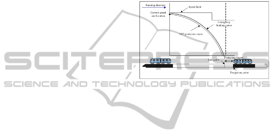
Shown in Figure 1.
The information of the position or the danger
point of the train ahead (named A) transmits to the
follow-up train B which is running in the line
interval through the wireless communication system.
For train B, position of train A is a danger point.
Train B calculates the maximum allowable speed to
the danger point. With train A moving forward, the
safe parking point of train B (stations do not belong
to safe parking points) also changes. Train B
calculates the speed-distance curve to the parking
points at real-time. When actual speed exceeds the
maximum allowable speed, the system alerts and
requires the train to decelerate. If the train fails to
decelerate to the maximum allowable speed within
the given time, the system will implement
emergency brake to ensure the safety of the train.
Figure 1: Operation principal of ATP system.
3 MODELING OF ATP SYSTEM
STRUCTURE
3.1 The General Model of ATP System
Now build the model of ATP system according to
section 2.2. The model mentioned in this paper takes
WLAN which is based on the standard of
IEEE802.11 to communicate between train and
ground (Hu, 2002). Use the advantages of WLAN
technology such as flexible using, convenient
installation, economic, easy extension to connect
ground equipment and on-board equipment through
the information transmitting platform. We can
achieve not only fast and real-time transmitting of
high capacity information but also closed loop
testing of train-ground information. The system will
be more advanced when supplied by positioning and
checking equipment (Chen et al., 2007). The general
model of ATP system in CBTC based on WLAN
includes 3 parts: regional control centre, on-board
equipment of the train and train-ground two-way
transmitting system (
Mirtchev, 2005). The general
model is shown in Figure 2.
3.2 Design of Regional Control Centre
The regional control centre is established in the
station where there is a bifurcation so that to
MODELING AND SIMULATION OF THE AUTOMATIC TRAIN PROTECTION IN WLAN BASED CBTC SYSTEMS
451
interlock this station with neighbouring bifurcated
stations and to control the ATP system. The control
targets are turnouts, protective signal equipments
and digital track circuits. The designed capacity of
this centre is: controlling range ≤5km; system
treatment cycle time200~250ms; the number
collected by relay (digital input) ≤500points; the
number controlled by relay (digital output)
≤500points (
Lamborn and Thomas, 2005); the
communication channel with neighbouring centres is
redundant fiber channel; the number of centres
whose interfaces can be connected ≤3.
Communication mode: two-way serial
communication; communication cycle time
(transmission) 200~250ms (Wang et al., 2005).
The wireless regional control centre which must
be operated safely is the core part of the entire ATP
system. Here redundant measurement, disperse and
isolate measurement are carried out. Redundant
measurement includes 3 levels (Xu and Tang, 2007):
system redundancy, net redundancy and power
supply redundancy. Disperse and isolate
measurement distributes control to all I/O modules
in order to reduce the burden on the host system by
I/O modules intellectualization. Meanwhile board-
level state testing and failure diagnosing are
implemented.
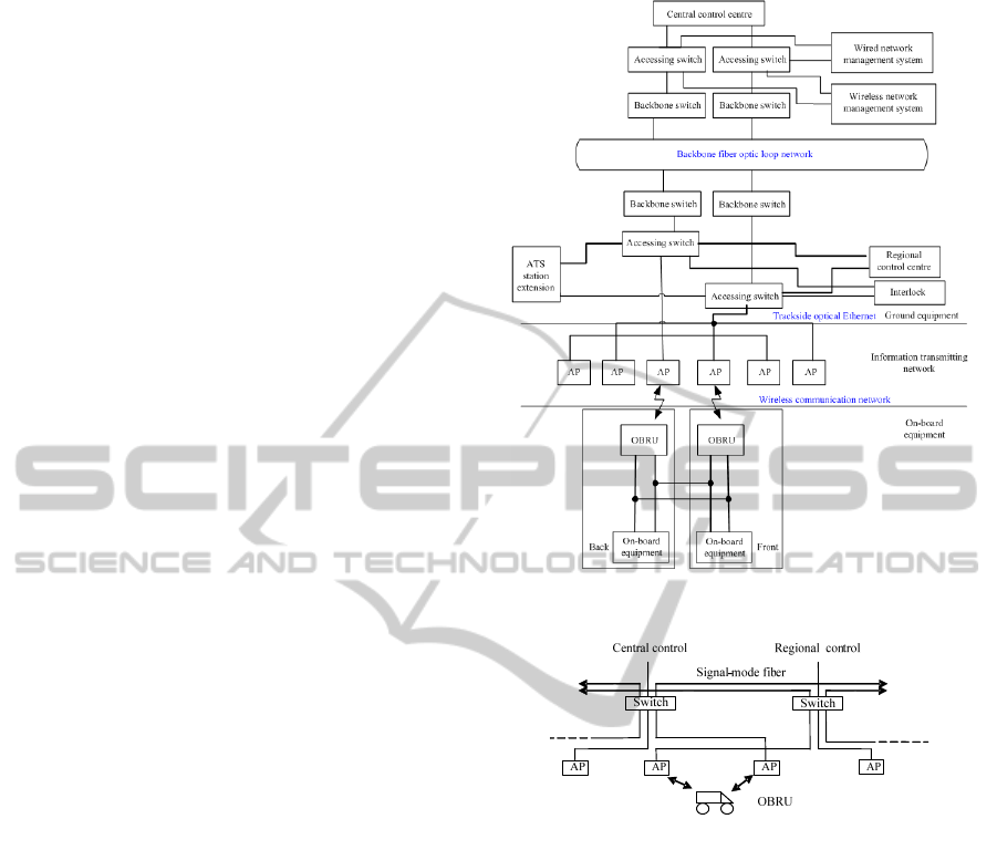
3.3 Construct of WLAN
Communication System
3.3.1 Structure of WLAN Communication
System
As the development of urban rail transit, data
communication system based on WLAN will
become the most widely used communication
system in CBTC considering of the advantages of
WLAN based on the standard IEEE802.11, for
example, it can be applied to the situation that needs
to connect with the net when moving and roaming; it
supports distant data processing and uneasy wiring
areas; its flexible using, convenient installation,
economic, easy extension and so on (Xu and Li,
2006). The wireless data communication network
consists of wired backbone network and wireless
mobile network. Its network structure is shown in
Figure 3.
WLAN communication system is the data
transmission platform between different parts of
ATP system (Zhang, 2007). The whole data
communication system includes 3 levels: Core level,
i.e., the backbone network. It’s the central of data
Figure 2: General model of ATP system.
Figure 3: Schematic diagram of wireless data
communication network.
communication system which is implemented by
redundant optical network with the characteristics of
high bandwidth and high reliability. Centre control
system and regional control system access to the
wired backbone optical network directly; Middle
level, i.e., the trackside network. It connects
backbone network and wireless network system. The
network extents following the route by network
switch which has accessed to the backbone network.
In this way the trackside network formed. This
network connects with wireless railside unit (WRU).
Thereby, the wireless access point (AP) can access
in it; Mobile level, i.e., the wireless network. This
network supports train-ground two-way mobile
communication. The trackside AP and on-board
wireless units (OBRU) on moving trains
communicate by wireless way. In this way, it
constructs a link between ground and moving trains.
One side of the wireless link is AP and the other side
ICEIS 2011 - 13th International Conference on Enterprise Information Systems
452

is on the train which connects with OBRU. WLAN
communication doesn’t mean totally wireless. There
are wired fiber between different regional control
centres. The equipment of whole communication
system includes: optical backbone network, AP,
wireless on-board equipment, interlocking
centralized station, switch in control centre and
router.
3.3.2 WLAN Ethernet Train-ground
Communication System
(1)Trackside Wireless Unit
One side of the wireless link is AP and the other side
is on the train which connects with OBRU. There is
an identification gateway for every switch’s ports
and OBRU. This gateway certificates the
identification of DCS message. To implement the
redundant of wireless network, every port of every
WRU connects with different switches. So a series
of redundant local network is supplied to WRU.
The switch of trackside network connects with
the supply chain of local WRU. This chain is
consisted of fiber. Considering of technology
demand and cost, multimode fiber is used generally.
WRUs are installed following the route about 250
per meter. Actual distance depends on detailed
survey, including terrain, tunnel structure, local
standard, antenna type and so on. Every AP on
WRU connects with Ethernet switches through local
servo chains. Every AP has two directional antennas
facing opposite directions.
Special transmit condition at the channel bend
and between distant stations should be considered
when arranging AP antennas. We should install
antennas according to the actual measured wireless
covered range whether it is channels or outdoors.
This way most factors that may influence signal
transmission would be involved so that there won’t
be any gaps under the cross covering by wireless
signals.
(2)OBRU
There’s an OBRU with moving wireless radio (MR)
station on each side of the train. In order to
implement the redundancy between trackside and
the train, these two OBRUs both connect with
VOBC. In addition, to diverse the receiving mode of
the signal, all MRs connect with 2 on-board
antennas. Each MR can search out at least 2 AP
signals at any time because of overlapping coverage.
To enhance the signal strength and reduce the
number of devices, these antennas are oriented.
3.4 On-board Subsystem
3.4.1 Structure of On-board Subsystem
ATP on-board equipment regard the information
received from the ground as a basis and generate a
speed Hijack curve to compare with the actual
speed. If actual speed exceeds the speed control
curve, on-board equipment will brake automatically.
According to principles of ATP on-board subsystem
and its mission, this paper refines it into different
functional modules. The train can protect itself
automatically by mutual coordination between all
functional modules. Main processor is the central
part to carry out different functional calculates. It
calculates output according to the settings of
application program and information from different
modules and drive corresponding parts using these
outputs.
3.4.2 Structure of Train Positioning
Technology System
Real-time, precise train positioning technology is a
premise to implement moving block urban rail
transit and is the basis for ATP system. This model
uses a technology called Wireless Spread Spectrum
Communication Location to implement real-time,
precise, train positioning and tracking under
complex environment. This technology includes
advanced wireless spread spectrum communication,
pseudo code ranging and computer information
processing technology. Wireless spread spectrum
communication location system accord with the
demand of ATP system based on WLAN. It can
locate precisely and is a completely independent
positioning system.
Set ranging base central controlling station on
the ground along with the trackside radios. Install
wireless spread spectrum communication transmitter
on both sides of the train. The transmitter sends
positioning information to the ranging base station
on the ground; after receiving the information, the
ranging base station calculates pseudo-range using
digital signal processing technology and transmits to
the central controlling station to precede data
processing through wireless or wired links. The
positioning result displays on e-maps and transmits
to trains by wireless way. The position of trackside
radio stations are fixed after accurate measurement.
All the radio stations are synchronization accurately
by synchronous clock. Trackside computers or on-
board computers will calculate the position of the
train according to the transmitting delay time of
different radios.
MODELING AND SIMULATION OF THE AUTOMATIC TRAIN PROTECTION IN WLAN BASED CBTC SYSTEMS
453

A WLAN is constructed by distributed radio
stations. Under most conditions, the area between
different stations can be covered by wireless reliably
and have redundancy. This kind of redundancy is a
self healing structure. When a radio station fails to
work, the system can rearrange and report the
location or number of the failed radio automatically.
So it won’t influence communication and train
controlling. Information of one radio station will be
received by 2 or even 3 radios generally. Spread
spectrum technology is design for military
application initially. It has the ability to transmit
under harsh electromagnetic environment. The
position of a train can be tested every 0.5s and the
positioning precision can reach to ±5m (
Stadlmann,
2008).
4 MODELING OF ATP
SPEED-DISTANCE BRAKING
CURVE
After building the model of ATP structure, this
section will research on ATP core algorithm
modelling, speed-distance braking curve modelling.
Train braking curve is the basis of over speed
protection of ATP system in CBTC based on WLAN.
The traction and braking force involved in this
model is determined according to “Order of train
traction calculation” (The Ministry of Railways of
The People’s Republic of China) promulgated by the
PRC Railway Ministry.
4.1 ATP Protection Curve
The function of braking is to ensure the train to stop
at a certain position or to limit the speed in a certain
range, i.e., the so-called “rash advance protection”
and “speeding protection”. Rash advance protection
is a special condition of speeding protection when
the limit terminal velocity equals to 0. But there are
some differences, for example, the result will be
different when distinguishing the braking safety
distance. In our design, all conditions are treated as
“speeding protection” because moving-blocking
method is used here. Expanse and adjust it to satisfy
precise controlling of all parameters. The train
braking distance formula after adjusting is shown as
formula (1).
jchh
mK
b
i
vvTv
S
0
22
00
1000
)(17.4
6.3
(1)
Where:
v
0
, v
m
—initial and terminal velocity of braking;
φ
h
—conversion friction coefficient of brake shoes;
θ
h
—conversion rate of train braking;
β
c
—common used braking coefficient;
ω
0
—unit basic resistance of the train;
i
j
—additional slop thousandths at braking section.
ATP system of urban rail transit monitors the
speed continuously to prevent from speeding. Firstly,
ATP system works out the maximum allowable
speed of the train at any time, i.e., the safe running
speed. If actual speed exceeds this speed, ATP
system will brake so that the actual speed can
decrease to safe speed in given time. In this process,
ATP speed-braking curve model is a most important
basis for speeding protection.
4.2 Algorithm to Determine
the Maximum Allowable Speed
There have been some fixed necessary engineering
data in ATP system such as route, slope, length of
track circuit, speed limit and so on. On-board ATP
equipment stores basic data about the train such as
mass and performance characteristics. First,
determine the position of the train by on-board
positioning system. On-board wireless equipment
transmits information including position code to
regional control centre through track WLAN. Then
regional control centre sends fixed engineering data
of the train position to on-board ATP equipment
through WLAN. On-board ATP computers work out
the maximum allowable speed curve based on this
model algorithm.
4.3 ATP Speeding Protection Process
After calculating the maximum speed and generating
the maximum allowable speed curve, on-board ATP
computers monitor the running speed and position of
the train. If actual speed curve exceeds the
maximum speed protection interface, ATP system
will cut off the train traction power immediately to
carry out protection braking.
The maximum allowable speed varies as the train
position changes. On-board ATP equipment makes
real-time and two-way communication with regional
control centre through WLAN. So ATP speeding
protection system is dynamic and real-time. This is
just the advantages of ATP system based on CBTC.
ICEIS 2011 - 13th International Conference on Enterprise Information Systems
454

5 SIMULATION OF ATP SYSTEM
OF CBTC BASED ON WLAN
In Section 3 and 4 we’ve built the models of ATP
system and ATP braking curve. The combination of
them can implement the main function of ATP
system, i.e., designated parking, speed monitoring,
speeding protection, distance and speed measuring,
gate controlling and interval controlling. Now build
a simulation platform based on LabVIEW to verify
the effect of this model.
5.1 Function of ATP System based on
WLAN
According to the main function of ATP system in
CBTC based on WLAN, this paper designs it into 4
functional modules:
(1)Basic data input subsystem
It is mainly used to set basic parameters for the
entire ATP system including 2 parts: structure of
route data and train data. Structure of route data
includes slop segment data, curve data and speed
limiting data. Structure of train data includes traction
braking characteristic curve data, mechanical
property data of the train and parameters.
(2)Speed controlling subsystem
It is used for speed monitoring, distance and
speed measuring and speeding protection. This
subsystem can prevent the train from speeding and
ensure the actual speed lower than allowable speed
which is determined by route, turnout, train and safe
controlling curve so that the train can run safely.
(3)Position testing and interval controlling
subsystem
It is used to protect the safe parking point and
control the running interval. This subsystem can
check running state of the train automatically and
generate a corresponding curve according to the
route environment so that the train can stop at safe
regions and rear collision can be avoided.
(4)Gate protection subsystem
It is used for protecting the safety of opening or
closing the door. This subsystem controls the
platform screen doors and safety doors to ensure the
security of passengers when the train stops or leaves.
5.2 Input and Output Design for ATP
System based on WLAN
Input and output design includes speed controlling,
position testing and interval controlling and gate
protection subsystem. The following example shows
the speed controlling subsystem.
5.2.1 Function Description
Speed controlling subsystem involves basic data
input system and speed controlling sub module.
Here is the train speed controlling sub module
simulation-IPO (Input-Process-Output) diagram, as
is shown in Figure 4.
Called by:
System name:ATP system in WLAN based CBTC
Calls for:
Initial input:line and curve data
Actual input:
current speed
running distance
work mode of ATP
drawing or braking choice
Choose curve data
End
Local data:Vo—ideal speed,Fi—drawing/braking force of last minute,Ni—speed series
index of drawing/braking characteristic curve,Nil—force series index of drawing/braking
characteristic curve
Module name:
Speed controlling subsystem
Speed controlling subsystem
Speed controlling subsystem
Basic data input subsystem
current speed limit of ATP
Actual output:
force series
start
current traction
Final output:null
Every 300ms
Obtain current speed limit,work mode of ATP and current speed,running distance
Make choice of drawing,coasting or braking according to current and ideal speed
Manually selection of drawing/braking series is available,default series is 1
Calculate drawing/braking force using interpolation method
Pass result of the choice,force series,current drawing force
Algorithm explanation:
Figure 4: IPO diagram of speed controlling subsystem.
5.2.2 Algorithm Explanation
Use interpolation method to calculate
traction/braking force: assume (V
1
, F
1
) and (V
2
, F
2
)
are two known points on the traction curve. Point
(V
X
, F
X
) is a point whose speed is known but force is
unknown and should be worked out.
When V
1
<V
X
<V
2
:
12 1
1
21
()()
X
X
F
FV V
FF
VV
(2)
Where:
F
X
—traction/braking force of the unknown point
(KN);
V
X
—current speed (km/h).
5.3 System Simulation and Calculation
5.3.1 Simulation Environment
Use LabVIEW virtual instrument development
platform of NI to develop the system. LabVIEW
MODELING AND SIMULATION OF THE AUTOMATIC TRAIN PROTECTION IN WLAN BASED CBTC SYSTEMS
455
(Zhang and Zhang, 2007) is currently a unique
worldwide graphical programming environment
based on data flow. According to the program of
simulation and test, this paper chooses LabVIEW
PDS, Measurement Studio, Signal Express and
LabVIEW add-on tools in NI Developer Suite.
ATP system of CBTC based on WLAN includes
initial parameter setting, speed controlling, position
testing, and interval controlling and gate protection.
Speed controlling is the central module of the entire
ATP system. It generates fixed or temporary speed
limit curve after inputting basic train information
and route information. It can also generate braking
curve according to the information from the control
centre.
The train and route parameters of this simulation
come from Rail Transit Line 2 of the straddling
monorail train and line data in Chongqing and are
simplified according to the model. Here, a section of
1.2km is chosen to simulate. In order to better reflect
the logic of the model all speed limits are attributed
to one parameter-interval speed limit which is set as
85km/h. In order to reflect the ability of the model to
adapt to various situations, all input data involved in
the software, including interval speed limit, can be
manually set to facilitate the testing of the system.
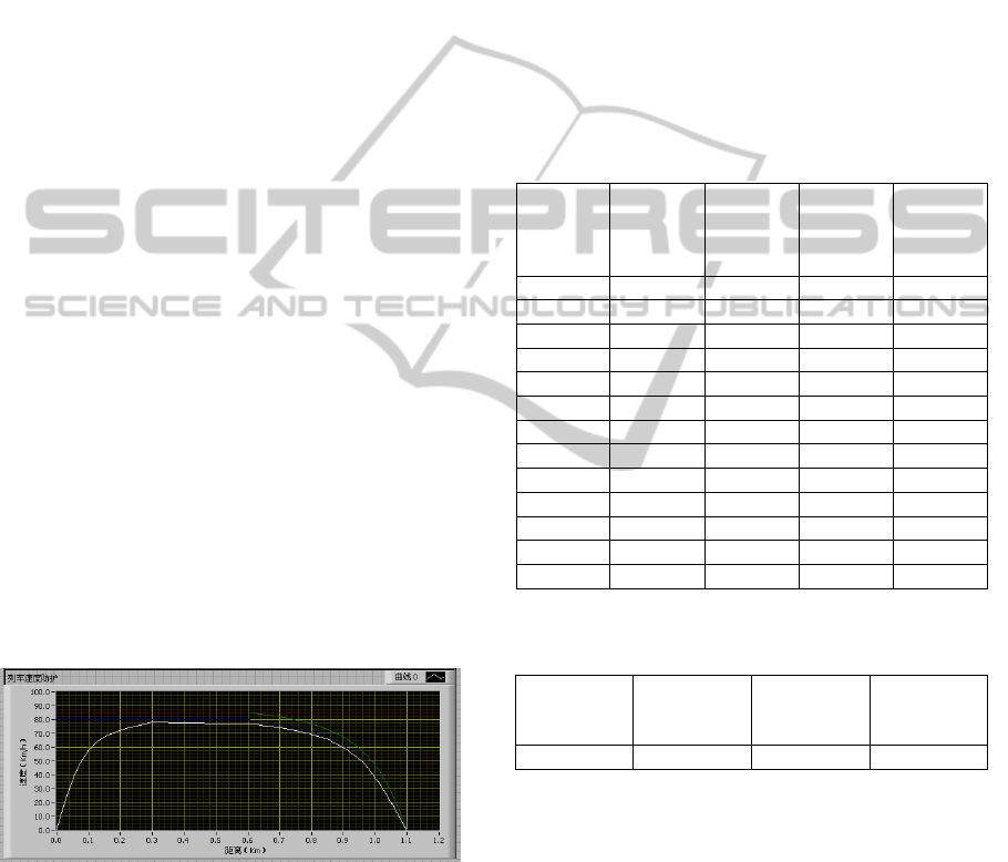
5.3.2 Simulation Result
Initial state: the train ahead runs under a constant
speed 85km/h and stops smoothly at 1.1km. The
distance between the train behind and the train ahead
is 0.5km. The train behind regards the front train as
target distance and target speed to adjust the
protection curve. The simulation result is shown in
Figure 5.
Figure 5: Braking curve of the train.
In this figure the red curve represents for interval
speed limit data. It’s obtained from reading data
which is set before the software runs. The green
curve represents for protection curve. It’s generated
by the model of ATP system. The blue curve
represents for target speed. It’s obtained by
decreasing the speed of protection curve by 3-7km/h.
This paper compared the simulation result with
actual auto protection curve obtained in the test
phase of Rail Transit Line 2 of the straddling
monorail train in Chongqing. Sampling point is
chosen as every 0.1km. The comparison result is
shown in Table1 and Table2.
5.3.3 Simulation Result Analysis
The braking curve, i.e., the speed-distance curve
indicates that if the train wants to stop at a certain
safe parking point with a certain initial speed, it
should start braking at a certain position to ensure
the train arriving right there according to braking
curve.
Table 1: Comparison of simulation speed and actual data.
Sampling
points
(km)
Protec-
tion
speed
(km/h)
Target
speed
(km/h)
Simula-
tion
speed
(km/h)
Actual
speed
(km/h)
0 85 80 0 79.52
0.1 85 80 57.61 78.98
0.2 85 80 72.09 78.76
0.3 85 80 77.94 78.03
0.4 85 80 77.47 77.57
0.5 85 80 76.89 77.08
0.6 85 80 77.00 76.65
0.7 82.17 76.44 74.13 76.12
0.8 77.19 71.05 69.38 73.78
0.9 67.23 60.19 59.97 68.43
1.0 45.86 38.61 38.54 45.57
1.1 0 0 0 0.01
1.2 — — — —
Table 2: Comparison of simulation stopping distance and
actual data.
ATP
stopping
distance(m)
Target
stopping
distance(m)
Simulation
stopping
distance(m)
Actual
stopping
distance(m)
1100 1098 1097.8 1098.5
Figure 5 shows that this model of ATP system
can implement the function of smooth parking and
speed protection. It can be found from Table1 that
the simulation speed is always lower than the target
speed and changes smoothly. The goal of controlling
the train to be safe and satisfying the comfort
requirement is able to achieve. At the point of 0.8km,
the actual speed is 73.78km/h. Although this speed
hasn’t reached ATP protection speed 77.19km/h, it
has exceeded target speed 71.05km/h already. As
soon as the actual speed exceeds the target speed,
the train will start to brake. It’s easy to cause
emergency brake. Thus, it doesn’t satisfy with the
ICEIS 2011 - 13th International Conference on Enterprise Information Systems
456

comfort requirement. However, ATP system in
CBTC based on WLAN in this paper improved the
situation that actual speed exceeds target speed when
the train runs because of transmission delay or
equipment limits. Table2 shows that this system is
able to satisfy the function of designated parking and
rash advance protection.
We can conclude after comparing the train
operation diagram and data:
(1)ATP system in CBTC based on WLAN
applies WLAN to CBTC so that it can communicate
wirelessly. It overcomes the disadvantages of
traditional ATP systems such as one-way
transmission, high cost and hard maintenance.
(2)The model build in this paper can calculate
the data of protection curve at real-time according to
two-way communication of WLAN and display
directly.
(3)ATP speed protection model, working as a
speed monitor, controls the train to run according to
the target speed curve. Running curve and protection
curve fits well.
(4)Under the monitor of ATP protection model,
the train meets the demand of protected parking. If
the train exceeds the parking section when entering
the station parking circle range, ATP system will
carry out full brake and monitor the train to ensure it
parking in front of the parking spot.
(5)This system takes hardware redundant of key
modules to satisfy with the reliable designing
requirements of single unit equipment. It also takes
advanced WLAN technology to implement strong
covering of wireless signals and improve the
reliability of internal communication.
(6)This system takes distributed network
structure, standard communication protocol, typical
division of module function and other measures to
improve equipment expansibility. It can meet some
special functional requirements of urban rail trains.
6 CONCLUSIONS
The research of CBTC based on WLAN has been a
research focus in the entire rail transit industry. In
this paper, we mainly focus on modelling of ATP
system in CBTC based on WLAN and propose
related frame structure and principle model
according to the study of ATP system and WLAN
technology combining with private ideas and
literature summary. We also focus on ATP speed-
distance curve modelling in detailed mathematics
and dynamics. Finally, we make simulation on the
ATP system in CBTC based on WLAN. The
functional modules of simulation, data structure and
IPO were designed for implementation of
simulation. And we also focus on simulation of
speed controlling module and analyze the simulation
result to verify the correctness of the model.
There are still imperfections that need further
study for the simulation of ATP system in CBTC
based on WLAN. A research of simulation on
channel establishment of the entire wireless
communication system in ATP has not been given
yet. Meanwhile, the signal security and system
stability problems are not solved. These are to be
researched for the next step.
ACKNOWLEDGEMENTS
This paper is partially supported by a fund of
Chinese Ministry of Railways with contract number
of “2010X001”.
REFERENCES
Cai, M.J., 2000. Automatic train protection and automatic
driving. Electronic Engineer, 26(8), 30-33.
Carr, D.W. Ruelas, R. Gutierrez- Ramirez, J.F. Salcedo-
Becerra, H., 2005. An Open On-Board CBTC
Controller Based on N-Version Programming. In:
International Conference on Computational
Intelligence for Modelling. Vienna November 2005.
Chen, H.F., Liu L., Xu S., 2005. Communication based
train control (CBTC) system. Railway Signalling &
Communication Engineering, 1,21.(In Chinese)
Chen, L., Ning, B., Xu, T.H., 2007. Research on
Modelling and Simulation of Vehicle-on-board
Automatic Train Protection Subsystem of
Communication Based Train Control System. In:
IEEE International Conference on Vehicular
Electronics and Safety, Proceedings.
Chen, G.F., Song, Q., 2007. Analysis of IEEE 802.11
based Wireless LAN Security. Guangdong
Communication Technology, 27(5), 35-39.(In Chinese)
Grappone, V.F., Hubbs, G.P., 2007. The Long Island Rail
Road Signal Strategy and its joint effort with New
York City Transit on communication-based train
control. IEEE, 33-34.
He, Z.T., 2005. ATP on-board equipment design principle
and implementation. Railway Signalling &
Communication, 41(C00), 19-21.(In Chinese)
Hong, D.C., 2006. Train-ground data communication of
urban rail transit ATP system. Railway Signalling &
Communication Engineering, 3(4), 14-15,19.(In
Chinese)
Hu, Y.H., 2002. Analysis and research of train protection
system under the condition of China train speed.
Chinese Railways, (8), 28-31.(In Chinese)
MODELING AND SIMULATION OF THE AUTOMATIC TRAIN PROTECTION IN WLAN BASED CBTC SYSTEMS
457

Lamborn, M., Thomas, M., 2005. Using fiber optic-to-
radio frequency (RF) conversion for communication-
based train control. In: Proceedings of the 2005
ASME/IEEE Joint Rail Conference. 2005, 181-186.
Mirtchev, A., 2005. Automatic Restart for Communication
Based Train Control Systems. In: Proceedings of the
2005 ASME/IEEE Joint Rail Conference. 2005, 177-
179.
Stadlmann, B., 2008. Basic Train Control System for
Regional Branch Lines - field Test Report. Computers
in Railways Xi- Computer System Design and
Operation in the Railway and Other Transit Systems,
253-262.
The Ministry of Railways of The People’s Republic of
China, 1999. Train traction calculation procedures.
Beijing: China Railway Publishing House. TBT1407.
Wang, C.L., Xiao, P., Kang, T.P., 2005. Train Control
System Security Model and Research Technology.
Journal of Transportation Engineering and
Information, 3(1), 36-39,56.(In Chinese)
Wu, X.Y., 2005. Analysis and Research on CBTC
algorithm for mobile ad hoc networks. Radio
Communications Technology, 31(6), 101-102.(In
Chinese)
Xu, G., Li, J.,2006. Development of wireless transmission
system in the automatic train control. Railway Survey
and Design, 5,35-38,44.(In Chinese)
Xu, T.H., Tang, T., 2007. The modeling and Analysis of
Data Communication System (DCS) in
Communication Based Train Control (CBTC) with
Colored Petri Nets. In: 8
th
International Symposium on
Autonomous Decentralized Systems.
Zhang, H., 2007. Wireless LAN applications in urban
mass transit. Urban Mass Transit, 10(2), 61-65.(In
Chinese)
Zhang, X.H., Zhang, Y.P., 2007. LabVIEW 8.20
Programming From Novice to Professional. Beijing:
Tsinghua University Press.(In Chinese)
Zhang, T.A., Li, L., 2008. Analysis of CBTC application
in subway though Guangzhou subway signal system.
Rail Transit, 11, 70-72.(In Chinese)
Zhou, P., Xu, H.Z., Hou, J.J., 2009. One Method to
Evaluate the Safety of Train Control Centre. In:
International Asia Conference on Informatics in
Control, Automation, and Robotics, Proceedings.
Thailand February 2009.
ICEIS 2011 - 13th International Conference on Enterprise Information Systems
458
