
Implementation of the Finite Automaton Public Key
Cryptosystem on FPGA
Dina Satybaldina, Altynbek Sharipbayev and Аigul Adamova
L. Gumilyov Eurasian National University, Munaitpasov str. 5
010000, Astana, Kazakhstan
Abstract. Hardware implementation aspects of the finite automaton public key
cryptosystem are discussed in this paper. A general architecture of the
multiplication of a square matrix on a vector over GF(q) is presented in the
paper. Our design was implemented on Altera EP3C5E144C8N of the Cyclone
III FPGA family. The performance of finite automaton public key
cryptosystems is mainly appointed by the efficiency of the underlying finite
field arithmetic. The results are compared with reported reconfigurable
hardware implementations of RSA. Proposed hardware realization of
cryptographic system allows organizing pipeline calculations.
1 Introduction
Today there are many distributed systems, which use communication resources that
must be safeguarded against eavesdropping or unauthorized data alteration. Thus
cryptographic protocols are applied to these systems in order to prevent information
extraction or to detect data manipulation by unauthorized users. Besides the widely-
used RSA method [1], other public-key schemes have gained more and more
importance in this context.
The public key cryptosystem on the basis of finite state machines (FSM) has been
offered by Tao Renji [2] and was named FAPKC (Finite Automaton Public Key
Cryptosystem). The private key consists of two FSM that are constructed so that their
inverses are easily calculated. The public key is the automaton which we get by
combining these two automata. It is believed to be hard to invert this combined
automaton without knowledge of the private key automata [1].
FAPKC cryptosystem is a stream ciphe. There are some modifications: FAPKC0
[2], FAPKC1 and FAPKC2 [3], FAPKC3 [4,5] and FAPKC4 [6]. The cryptosystem
can be used as for enciphering (with using public key) and for decryption (with using
FSM, which is reversed to public key), and for signing (by this FSM) and for check of
the signature (by public key) [6, 7].
Cryptographic transformations can be implemented in both software and hardware
[8]. Software implementations are designed and coded in programming languages,
such as C, C++, Java, and assembly language, to be executed, among others, on
general purpose microprocessors, digital signal processors, and smart cards. Hardware
implementations are designed and coded in hardware description languages, such as
VHDL and Verilog HDL, and are intended to be realized using two major
Satybaldina D., Sharipbayev A. and Adamova A..
Implementation of the Finite Automaton Public Key Cryptosystem on FPGA.
DOI: 10.5220/0003594301670173
In Proceedings of the 8th International Workshop on Security in Information Systems (WOSIS-2011), pages 167-173
ISBN: 978-989-8425-61-4
Copyright
c
2011 SCITEPRESS (Science and Technology Publications, Lda.)

implementation approaches: application-specific integrated circuits (ASICs) and field
programmable gate arrays (FPGAs).
In this paper we describe an implementation method of FAPKC. The method is
based on realization of computational structure in GF(q). A project was implemented
on the programmed matrix FPGA EP3C5E144C8N of the device family Cyclone III
offered by Altera.
2 FAPKC Principles
2.1 Definitions and Denotations
Let us introduce the basic terminology [5]:
Definition 1. Finite automaton M – a quintuple <X, Y, S,
δ
,
λ
>, where we have the
input alphabet X, the output alphabet Y and the state alphabet S which all are
nonempty finite sets and the transition function
δ
:S
×
X→S and the output function
λ
:S
×
X→Y which are single valued functions.
If we denote by A
N
the set of all finite words of alphabet A, by A
ω
the set of all
infinite words of alphabet A and by ϵ the empty word, we can expand the domains of δ
and λ to S ×X
N
and S × (X
N
∪ X
ω
), respectively, as follows:
δ(s, ϵ ) = s, δ(s, αx) = δ(δ(s, α), x), (1)
λ(s, ϵ ) = ϵ, λ(s, xα′) = λ(s, x) λ(δ(s, x), α′), (2)
where s ∈ S, x ∈ X, α ∈ X
N
and α′ ∈ X
N
∪ X
ω
.
Definition 2. Let M = <X,Y,S,K,
δ
,
λ
> be a finite automaton, X and Y are column
vector spaces over GF(q) of dimension l and m, respectively, and τ be a nonnegative
integer. M is a weakly invertible with delay τ if, for any x
i
∈
X, i =0, 1, …, τ and s
∈
S, x
0
can be uniquely determined by the state s and the output λ(s, x
0
…x
τ
).
For any states s ∈ S and s′ ∈ S, if ∀α ∈ X
ω
, ∃α
0
∈ X
N
:
λ′ (s′, λ(s, α)) = α
0
α and |α
0
| = τ, (3)
then (s′, s) is a matching pair with delay τ or s′ matches s with delay τ .
Definition 3. Let M = <X, Y, S,
δ
,
λ
> and M′ = <Y, X, S′, δ′, λ′> be two finite
automata and τ be a nonnegative integer. M′ is a weak inverse with delay τ of M if, for
any s ∈ S, there exists s′ in S′ that (s′, s) is a matching pair with delay τ.
Definition 3. Let M
1
= <X, Y, S
1
,
δ
1
,
λ
1
> and M
2
= <X, Y, S
2
,
δ
2
,
λ
2
> be two finite
automata. Superposition of M
1
and M
2
is a finite automaton C(M
1
,M
2
) = <X
1
, Y
2
, S
1
×
S
2
, δ, λ >, where
δ(<s
1
, s
2
>, x) =<δ
1
(s
1
, x), δ
2
(s
2
, λ
1
(s
1
,
x
))> (4)
λ(< s
1
, s
2
>, x) = λ
2
(s
2
, λ
1
(s
1
, x)), (5)
for any x ∈ X
1
and s
1
∈ S
1
, s
2
∈ S
2
.
Definition 4. Let
ϕ
be a mapping from Y
k
× X
h+1
to Y. This mapping defines
M
ϕ
=<X,Y,Y
k
×X
h
,δ,λ> to be an (h, k)-order memory finite automaton if
y(i) =
ϕ
(y(i − 1), . . . , y(i − k), x(i), . . . , x(i − h)), i = 0, 1, . . . (6)
168

If the mapping
ϕ
is from X
h+1
to Y then M
ϕ
is an h-order input memory finite
automaton.
2.2 Brief Overview of FAPKC Cryptosystems
In the paper [5] it was shown how to break the FAPKC cryptosystem if not a suitable
nonlinear automaton is used. From the mathematical point of view of rules and
conditions finding of invertible nonlinear automata of the suitable form and
superposition of its are in detail considered in [5,9]. Therefore here we will consider
only the cryptographic algorithm steps for encryption/decryption without
mathematical calculations.
Let X and Y be column vector spaces over GF(q), with dimension l.
A FAPKC3 user A chooses his own public key and secret key as follows:
(1) Construct two automata: an (h
0
, k
0
)-order memory finite automaton M
0
=<X, Y,
S
0
, δ
0
, λ
0
> and a (τ
0
+ k
0
, h
0
)-order memory finite automaton M
0
*
=<Y, X, S
0
*
, δ
0
*
, λ
0
*
>.
(2) Construct an h
1
-order input memory finite automaton M
1
==<X, X, S
1
, δ
1
, λ
1
>
and a (τ
1
, h
1
)-order memory finite automaton M
1
*
==<X, X, S
1
*
, δ
1
*
, λ
1
*
>.
(3) Construct the finite automaton C′(M
1
,M
0
) =< X, Y, S, δ, λ > from M
1
and M
0
.
(4) Denote τ = max(τ
0
, τ
1
, h
0
).
Choose an arbitrary state
=
〈
,
…
,
,
,
…
,
〉
of C′ (M
1
,M
0
) to
be the starting state for encryption. Compute
′
,
…′
,
=
λ
(
〈
,
,…
,
〉
,
,
…
,
(7)
Define parts needed in decryption
,
=
〈
,
,…,
,
〉
(8)
and
,
=
〈
′
,
,…,′
,
〉
(9)
(5) The public key of the user A is {C′(M
1
,M
0
), s
e
, τ
0
+ τ
1
}.
The secret key of the user A is {
∗
,
∗
,
,
,
,
,
,
}.
Encryption. When user B wants to send to user A a plaintext x
0
… x
n
in secret, he
first adds some τ
0
+ τ
1
letters x
n+1
… x
n+τ0+τ1
to the end of the plaintext. Then he can
compute the ciphertext using A’s public key:
…
=
λ
,
…
. (10)
Decryption. After receiving the ciphertext
…
, user A first computes
using parts
∗
and
,
of his secret key and part
,
…
,
of his public key
′
…′
=
λ
∗
(
〈
,
,…
,
,
τ
,…,
,
,
…
,
〉
,
…
). (11)
Then using parts
∗
and
,
of his secret key user A retrieves the plaintext
…
=
λ
∗
(
〈
,
,…
,
,′
τ
,…,
〉
,′
…′
). (12)
As present in [5] automaton M
0
is in the form of
(
)
=
∑
( − )
+
∑
(
−
)
, = 0,1, …
(13)
169

and
∗
in the form of
(
)
=
∑
∗
( − )
+
∑
∗
(
−
)
, = 0,1, …
(14)
The nonlinear automaton M
1
is in the form of
′
(
)
=
∑
( − )
+
∑
∗
(
−
)
,…,
(
−−
)
, = 0,1, …
(15)
where
(
−
)
,…,
(
−−
)
is a nonlinear function from X
ϵ+1
to X, ϵ is a small
positive integer.
Then C′(M
1
,M
0
) can be expressed by
(
)
=
∑
( − )
+
∑
(
−
)
+
∑
(
−
)
,…,
(
−
−
)
, = 0,1, … (16)
where
=
∑
,
,
(17)
and
′
=
∑
′
,
,
(18)
Parameters h
0
, h
1
, k
0
, τ
0
and τ
1
may be chosen by users.
3 FPGA Implementation of FAPKC
3.1 Hardware Implementation Environment
In this paper FAPKC3 was implemented on the programmed matrix Altera FPGA of
the device family Cyclone III (EP3C5E144C8N). This Cyclone III device has a total
of 5,136 logic elements, 23 multipliers, 2 phase-locked loops (PLLs) [10]. Quartus II
Web Edition software includes an integrated development environment to accelerate
system-level design and seamless integration with leading third-party software tools
and flows [11].
3.2 Implementations Details
The equations show that multiplication of a square matrix on a vector is the basic
operation in algorithm FAPKC3. Matrix Аr[n, n], a vector V[n], dimension of a matrix
are input parameters for the given procedure. P [n] is a resultant vector. Each element
of a resultant vector calculated by search of elements of lines of matrix Аr and their
multiplication to corresponding elements of a vector V. The result of multiplication
increases to current value of an element of vector P. Each element of a resultant
vector is calculated by the following formula:
=
∑
∙
(19)
170
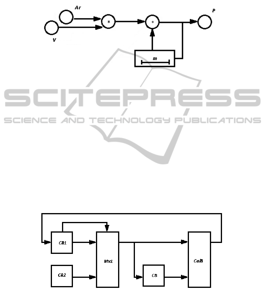
The information graph of calculation realization according to the formula (19) is
presented in Figure 1.
Fig. 1. The graph of multiplication of a matrix on a vector-column. Аr and V – input
information tops, Р – output information top, m – depth of a delay line.
Depth of a delay line is equal to m, size of a vectors stream. Thus for the stream of
vectors V we have:
=
〈
…
…
…
…
〉
, (20)
where the top index means a vector’s element, the bottom index means number of
vector in the stream.
Thus, elements streams of matrix and vectors from information tops Аr and V
accordingly are put on multiplier inputs. Further, the result of multiplication is added
with earlier keeped value of an element of vector P from the delay line.
The structure of block P, which is used for multiplication of a matrix on vectors
stream, is presented on Figure 2. CR blocks provide communication of the computing
scheme with memory cells from which commands and the data are read out and
written. CR1 is designed for storage and getting of commands and lines elements of
a matrix, and also for writing of calculation results from CalB. CR2 it is designed for
storage and getting of vectors stream.
Fig. 2. Structure of calculator P: CR1, CR2 – controllers of the memory; Мx1 – the
multiplexer of choice CR1 or CR2; CB – the control block; CalB – the calculation block.
171
Multiplexer Mx1 is used for switching of the input data flows to CalB. At each
moment of time on CalB arrives:
- elements of a matrix line for their preservation in the internal buffer (loading
of elements of a matrix),
- or elements of stream vectors for computing structure (performance of
calculations). Commands to CB are arrive from CR1.
CB is designed for decoding of commands and formation of control signals for
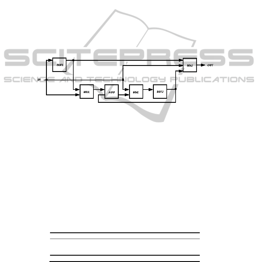
management of calculations by CalB. The structure of CalB block is presented on
Figure 3.
Buffer BUF1 is used for storage of a matrix line. Multiplier MUL, adder ADD and
a delay line BUF2 realize calculations according to an information graph as shown on
Figure 1. Multiplexer Mx2 is intended for switching of the input data flows to CalB.
Data flows represent streams of matrix lines, streams of vectors and streams of
results. Multiplexer Mx1 is intended for switching of streams of intermediate results
and results from previous CalB, which come into buffer BUF2. Thus, hardware
realization of set CalB allows organizing pipeline calculations.
Fig. 3. The structure of calculatoin block CalB.
3.3 FPGA Implementations Results
The proposed architecture was captured by using VHDL. All the system components
were described with structural architecture. The system tested using confirmed test
vectors [5] in order to examine its correctness. The whole design was synthesized,
placed and routed by using Altera FPGA device (Cyclone III, EP3C5E144C8N) [10].
Synthesis results for the proposed implementation are obtained as follows: 4,314 logic
elements used (84% from available area) at a maximum frequency of 45 MHz and
data rate of 24,3 Kb/s.
The maximum operating frequency F as well as the number of logic elements
required for our implementation was obtained from the Quartus II Web Edition
software. Comparison between the proposed FAPKC implementation and a 512-bit
RSA implementations are presented in Table 1. Area resource comparisons are not
given because they are not provided by the other implementations.
Table 1. Public key cryptosystem implementations comparison.
Public key cryptosystem F (MHz) Data rate (Kb/s)
RSA in [12] 45.6 140-460
RSA in [13] 100 100
RSA in [14] 50 43
Proposed 45 MHz 24,3
172

4 Concluding Remarks
FAPKC implementation oriented on multiplication of a square matrix on a vector
over GF(q) on the reprogrammable matrix is offered in this paper. FAPKC3 was
implemented on Altera FPGA of the device family Cyclone III (EP3C5E144C8N).
The proposed system achieves a data throughput up to 24,3 Kb/s in a clock
frequency of 45 MHz. The most part of an integrated circuit area (84%) was used in
our FPGA implementation of FAPKC3 with small parameters (q = 2, l = 3, h
0
= 1, k
0
= 2 and τ
0
= 1).
Thus, a future work will to concern of the implementation of FAPKC with the
large parameters. The most obvious extension is to design a fully pipelined
architecture in order to obtain a higher throughput at the price of area.
References
1. Schneier, B.: Applied Cryptography: Protocols, Algorithms, and Source Code in C. John
Wiley & Sons, New York (1996).
2. Tao R. C. and Chen S. H.: A Finite Automaton Public Key Cryptosystem and Digital
Signatures. Chinese J. of Computer 8 (1985) 401-409.
3. Tao R. J. and Chen S. H.: Two Varieties of Finite Automaton Public Key Cryptosystem and
Digital Signatures. J. of Compt. Sci. and Tech.1 (1986) 9-18.
4. Tao R. J. and Chen S. H. and Chen X. M. FAPKC3: a new finite automaton public key
cryptosystem. ISCAS–LCS–95–07. Chinese Academy of Sciences, Beijing (1995).
5. Meskanen, M.: On Finite Automaton Public Key Cryptosystems. TUCS Technical Report,
408 (2001).
6. Tao, R. J. and Chen S. H.: The generalization of public key cryptosystem FAPKC4.
Chinese Science Bulletin, Vol. 44 (1999) 784-790.
7. Xiang, G.: Finite automaton public key cryptosystems and digital signatures - analysis,
design and implementation. Dissertation (in Chinese). Institute of Software. Chinese
Academy of Sciences, Beijing (1994).
8. Çetin Kaya Koç (ed.): Cryptographic Engineering. Springer Science+Business Media, New
York (2009).
9. Tao, R. J.: Finite Automata and Application to Cryptography. Jointly Published with
Tsinghua University Press (2009).
10. Cyclone III device handbook. Available at the web site “http:// www.altera.com
/literature/lit-cyc3.jsp”.
11. Quartus II handbook v10.1.0. Available at the web site “http:// www.altera.com
/literature/lit-qts.jsp”
12. Blum, T. and Paar, C.: High–Radix Montgomery Modular Exponentiation on
Reconfigurable Hardware. IEEE Transactions on Computers, Vol. 50, No. 7 (2001) 759 -
764.
13. Chih-Yuang Su, Shih-Arn Hwang, Po-Song Chen, and Cheng-Wen Wu: An Improved
Montgomery’s Algorithm for High-Speed RSA Public-Key Cryptosystem. IEEE
Transaction on Very Large Scale Integration (VLSI) Systems, Vol. 7, No. 2 (1999) 280 -
284.
14. Chen, P. S., Hwang, S. A. and Wu, C. W.: A systolic RSA public key cryptosystem. In
Proceedings of International Symposium of Circuit and System (ISCAS’96), Vol. 4 (1996)
408-411.
173
