
Towards the Refinement of Topological Class Diagram as
a Platform Independent Model
Uldis Donins, Janis Osis, Armands Slihte, Erika Asnina and Bernards Gulbis
Department of Applied Computer Science, Institute of Applied Computer Systems
Riga Technical University, Meza iela 1/3, Riga, LV 1048, Latvia
Abstract. In this paper a refinement process of topological class diagram is pre-
sented. The refinement process is aimed to lower the abstraction level of the ini-
tial topological diagram which is obtained from the topological functioning
model. Topological functioning model uses mathematical foundations that ho-
listically represent complete functionality of the problem and application do-
mains. By lowering abstraction level of the topological class diagram, it gets
additional information which is needed during the software development and
maintenance phases. The refinement process consists of six steps. As a result of
applying refinement process, a rich topological class diagram with lower ab-
straction level is obtained. The refinement process is a part of topological mod-
eling approach and it is shown in the context of laundry business system soft-
ware development project. By applying topological modeling approach it is
possible to enable computation independent model creation in a formal way and
to enable transformation from it to the platform independent model.
1 Introduction
The topological modeling approach for business systems modeling and software sys-
tems designing given in [15] is aimed to enable Computation Independent Model
(CIM) creation in a formal way and to enable transformation from it to Platform Inde-
pendent Model (PIM) in the context of Model Driven Architecture (MDA) [9]. It is a
model-driven approach and it combines Topological Functioning Model (TFM) [11]
and its formalism with elements and diagrams of TopUML [15] (a profile based on
Unified Modeling Language (UML) [10]). Despite the fact that there are a number of
UML profiles created [17], no one of them uses topology from TFM in conjunction
with UML elements.
At the moment there exist a number of Model-Driven Software Development me-
thods, but according to [8] only a few methods include the requirements discipline in
the Model-Driven Development process. The main drawback of the most software
development methods or approaches is that the beginning of the software development
is too fuzzy and lacking a good structure. Therefore, for example, the CIM-to-PIM
conversion depends much on designers’ personal experience and knowledge and the
quality of PIM cannot be well controlled [12] [20]. As a result of this drawback we
Donins U., Osis J., Slihte A., Asnina E. and Gulbis B..
Towards the Refinement of Topological Class Diagram as a Platform Independent Model.
DOI: 10.5220/0003583600790088
In Proceedings of the 3rd International Workshop on Model-Driven Architecture and Modeling-Driven Software Development (MDA & MDSD-2011),
pages 79-88
ISBN: 978-989-8425-59-1
Copyright
c
2011 SCITEPRESS (Science and Technology Publications, Lda.)

can agree with Mr. Jones [6] that the way software is built remains surprisingly primi-
tive. We are considering that by formalizing the very beginning of the software devel-
opment life-cycle it is possible to build a better quality software systems and as shown
in [15] – to enable CIM-to-PIM conversion.
By using the TFM construction approach given in [16] it is possible to automate
the creation of TFM of business system. The automation of TFM creation is gained by
applying natural language processing on business use cases. By following the guide-
lines of PIM creation by means of topological class diagrams given in [15], the initial
topological class diagram gets developed by applying transformations on TFM. This
topological class diagram can be considered as initial, because it shows only the
classes and topological relations between them. The topological relations between
classes show the control flow within a system. They are a strong relation because this
relation exists between functional features, objects and even classes. Initially topolog-
ical relation is identified between functional features and after that by applying trans-
formations it is transferred further as the same relation between objects and classes. In
spite of having topological relations between classes a refinement of topological class
diagram should be performed in order to find and define generalized classes, structural
relationships, enumerations, and provided and required interfaces.
There are a number of related works in class diagram modeling and refinement, for
example, [1], [2], [7], [18], and [19]. The UML user guide [3] also contains guidelines
for modeling with UML diagrams and elements. Mainly all mentioned methods are
intended to evolve classes and relations between them by reviewing previously created
software artifacts (like use cases, requirements specification, etc.) and by doing addi-
tional interviews. This is an informal way in software development which is mainly
based on the discretion of designer [14]. Since the mentioned methods are supposed to
deal with standard UML class diagrams, at the moment there exist no method for
improving the quality and structure of topological class diagrams.
The main goal of this research is to provide guidelines for topological class dia-
gram refinement in order to lower the abstraction level of the initial topological class
diagram. As an example of initial topological class diagram is used topological class
diagrams for laundry business system as given in [15]. This paper is organized as
follows. Section 2 describes the PIM development by means of topological class
diagram. By applying described process in software development the initial
topological class diagram is developed in accordance to the CIM. Section 3 gives
guidelines in detail for the topological class diagram refinement. The refinement
process consists of six steps: identifying generalizations, defining both provided and
required interfaces, identifying structural relationships between classes, identifying
enumerations, checking for additional relationships (such as dependencies and
realizations), and revising topological class structure. Section 4 gives conclusions of
our research and future research direction.
2 Topological Modeling and the Initial Topological Class Diagram
There are two stages at the beginning of the problem analysis: the first one is analysis
of the problem domain and the second one is analysis of the solution domain. These
80
levels should be analyzed separately. The first idea is that the application context
constrains the business context, not vice versa (fully satisfies [5]). The second idea is
that functionality determines the structure of the planned system. Having knowledge
about the complex system that operates in the real world, a TFM of this system can be
composed. This means that the TFM of the system validates functional requirements
and can be partially changed by those requirements [13]. Construction of TFM and
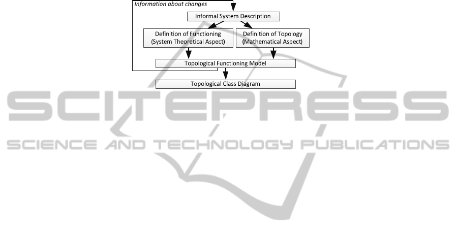
topological class diagram is shown in Fig. 1.
Fig. 1. Construction of Topological Functioning Model and Topological Class Diagram.
TFM has strong mathematical basis and is represented in a form of a topological
space (X, Θ), where X is a finite set of functional features of the system under consid-
eration, and Θ is the topology that satisfies axioms of topological structures and is
represented in a form of a directed graph. The necessary condition for constructing the
topological space is a meaningful and exhaustive verbal, graphical, or mathematical
system description. The adequacy of a model describing the functioning of a specific
system can be achieved by analyzing mathematical and functional properties of such
abstract object. The TFM has topological characteristics: connectedness, closure,
neighborhood, and continuous mapping (definition of topology on Fig. 1). Despite that
any graph is included into combinatorial topology, not every graph is a topological
functioning model. A directed graph becomes the TFM only when theoretical substan-
tiation of the systems is added to the above mathematical substantiation. The latter is
represented by functional characteristics: cause-effect relations, cycle structure, and
inputs and outputs (definition of functioning on Fig. 1). At least one directed closed
loop must be present in every topological model of system functioning. This loop
shows the “main” functionality that has a vital importance in the system’s life. Usually
it is even an expanded hierarchy of cycles. Therefore, a proper cycle analysis is neces-
sary in the TFM construction, because it enables careful analysis of system’s operation
and communication with the environment. [11]
After the construction of TFM it is possible to transform topology defined in TFM
into class diagrams (it is possible because the TFM has strong mathematical basis). In
this way it means that between classes are precisely defined relations which are identi-
fied from the problem domain. In traditional software development relations (mostly
associations and generalizations) between classes are defined by the designer’s discre-
tion. [14]
In order to develop a topological class diagram, after the creation of TFM a graph
of problem domain objects must be developed and afterwards transformed into a topo-
logical class diagram. In order to create problem domain object graph, it is necessary
to detail each functional feature of the TFM to a level where it uses only one type of
81

objects. After construction of problem domain object graph all the vertices with the
same type of objects and operations must be merged, while keeping all relations with
other graph vertices. As a result, topological class diagram with attributes, operations
and topological relationships is defined as shown in [15].
The abstraction level of initial topological class diagram is high. In order to lower
it, a refinement of initial topological class diagram should be done. During the refine-
ment process both other types of relations and classifiers are introduced. The refine-
ment process in detail is given in next section.
3 Refinement of Topological Class Diagram
The refinement of topological class diagrams is aimed to lower abstraction level of it.
By lowering abstraction level the diagram gets additional information which is needed
during the software development and later also during its maintenance. The refinement
process consists of six steps:
1. identify generalizations (basing on topological relationships, attributes, operations,
and responsibilities),
2. define interfaces (both provided and required),
3. identify structural relationships between classes (aggregations, compositions, and
associations),
4. identify enumerations,
5. check for additional relationships (such as dependencies and realizations), and
6. revise topological class structure.
These refinement process steps are described in detail in the following subsections. As
a result of applying refinement process, a rich topological class diagram with lower
abstraction level is obtained.
3.1 Identifying Generalizations
A generalization is a relationship between a general kind of thing (called the super-
class or parent) and a more specific kind of thing (called the subclass or child). Gene-
ralization sometimes is called an “is-a-kind-of” relationship. If subclass has one super-
class then it is single inheritance. If subclass has two or more superclasses then it is
multiple inheritance. [3]
The generalizations can be identified in two ways. The first way is to review initial
topological classes which are obtained from the TFM. To find a generalization you
need to look for the same responsibilities, topological relationships, attributes, and
operations that are common to two or more classes. The set of common responsibili-
ties, topological relationships, attributes, and operations can be elevated to a more
general class. If this general class does not exist it can be created. Since topological
relationships define control flow within system, by introducing general classes and
generalization relationships it is possible that the more general class is placed at the
end of topological relationship and the more specific class is placed at the beginning
82
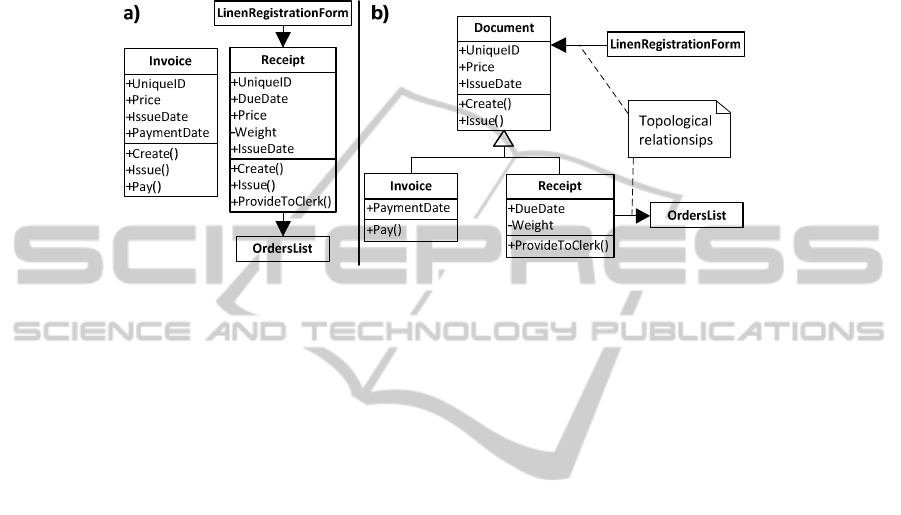
of topological relationship (see Fig. 2). In order to help identifying generalizations,
during the review process of initial topological classes, an additional attention can be
paid on anywhere where the initial topological classes indicates that there is more than
one “kind of” thing (for example, two kinds of documents (see Fig. 2b). This indicates
a possible generalization.
Fig. 2. Initial topological classes (a) and generalized topological classes (b) showing topologi-
cal and generalization relationships between them.
The second way is by doing additional interviews with stakeholders. During the in-
terviews the interviewees are asked if any of the classes are variations on others. By
applying both ways in generalization identification a more formal (by reviewing initial
topological classes) and less formal (by making interviews) approaches are used. The
reviewing process is more formal because it is based on sets of already existing infor-
mation. Reviewing and introduction of generalization relationships (together with
superclasses) can be automated. By using together reviewing and interviewing an
additional model checking gets performed.
3.2 Defining Interfaces for Collaboration with Environment
An interface is a collection of operations that are used to specify a service of a class or
a component. Graphically, an interface may be rendered as a stereotyped class in order
to expose its operations and other properties. Interfaces may also be used to specify a
contract for a use case or subsystem. [10]
We can draw a line around the topological class diagram which is obtained by ap-
plying transformations on the TFM, thus showing the boundary of the system under
consideration. The next step is to identify the operations and the signals that cross this
boundary. These operations and signals can be found by analyzing both the TFM and
the topological space of the system (the TFM shows the functioning of the system, but
topological space shows the system within the (surrounding) environment). This anal-
ysis shows the inputs and outputs of the system. The input functional features within
TFM indicate the provided interfaces, but the output functional features indicate the
required interfaces. Required (imported) interfaces are modeled by using dependen-
cy relationships, and provided (exported) interfaces are modeled by using realization
83
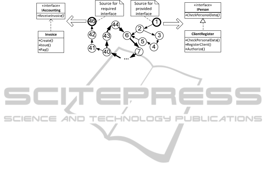
relationships. An example of showing analysis of TFM and topological space and the
resulting interfaces are given in Fig. 3.
Fig. 3. Fragment of topological space and examples of provided and required interfaces.
By using the guidelines given in [3] it is possible to model interfaces within the
system as a seams between different parts of the system.
3.3 Identifying Structural Relationships
The identification of physical relationships between entities involved in the system
consists of three steps. At first it is needed to check and find the whole and part rela-
tionships – aggregations and compositions.
Aggregation is a “has a” relationship meaning that an object of the whole has objects
of the part. [4] If objects are related with an aggregation then by destroying the object
of the whole, the objects of the part is not destroyed. Aggregation is a special kind of
association. According to guidelines given in [18], aggregation can be placed between
objects if a part object can belong to more than one whole object and the part contin-
ues to exist when the whole is destroyed. Words that suggest aggregation include
“collection”, “list”, and “group”.
Composition is a form of aggregation, with strong ownership and coincident lifetime
as part of the whole. Parts with non-fixed multiplicity may be created after the compo-
site itself, but once created they live and die with it. This means that, in a composite
aggregation, an object may be a part of only one composite at a time and by destroy-
ing whole, the parts are destroyed with it [4]. According to guidelines given in [18],
composition can be placed between objects if a part is totally “owned” by the whole
and the part ceases to exist when the whole is destroyed. Words that suggest composi-
tion include “composed of” and “component”.
After identification of aggregations and compositions, the next step is identification of
associations between classes. An association is a structural relationship that specifies
that objects of one thing are connected to objects of another. Given an association
connecting two classes, it is possible to relate objects of one class to objects of the
other class [10]. According to guidelines given in [3], associations can be placed be-
tween objects if it is needed to navigate from objects of one type to objects of another.
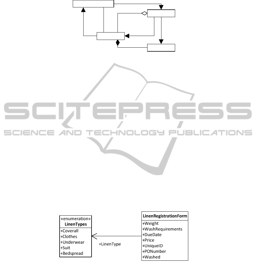
This is a data-driven view of associations. An example of identified structural rela-
tionships in the context of laundry system is given in Fig. 4.
84
LinenRegistrationForm
Invoice
Order
OrdersList
1
1
1
1
0..*
1
Fig. 4. Example of identified structural relationships between classes LinenRegistrationForm,
Order, Invoice, and OrdersList.
3.4 Identifying Enumerations
According to the [10] an enumeration is a data type whose values are enumerated in
the model as enumeration literals. Enumeration is a kind of data type, whose instances
may be any of a number of user-defined enumeration literals. An enumeration may be
shown using the classifier notation (a rectangle) with the keyword «enumeration».
The enumeration within a system can be found in two ways. The first way is to re-
view initial topological classes which are obtained from the TFM of the system under
consideration. To find enumerations at first you need to look for attributes which can
contain only a restricted set of values. In the context of the laundry system, an exam-
ple of the restricted set of values is the requested washing type. The second thing is to
search for objects which can change its state value during its lifetime. In the context of
the laundry system, an example of such object is washing request. The washing re-
quest can have different states, for example, new, registered, in washing, completed,
paid. The second way is by doing additional interviews with stakeholders. During the
interviews the interviewees are asked if any of the attributes has only limited list of
allowed values or if there exist a states of things involved into system. If such lists of
values or states exist, then enumerations should be defined for each such list. An ex-
ample of identified enumerations is given in Fig. 5.
Fig. 5. Example of identified enumeration in linen registration form.
3.5 Checking for Additional Relationships
The checking of additional relationships includes identification of dependencies and
realizations.
A dependency is a relationship that states that one thing (for example, class Invoi-
85

ce (in the context of laundry system)) uses the information and services of another
thing (for example, class ClientCard (in the context of laundry system)), but not neces-
sarily the reverse. Dependency relationship should be used to show that one thing is
using another. Most often dependencies between classes are used to show that one
class uses operations from another class or it uses variables or arguments typed by the
other class. Dependencies also most often show required interfaces of a class (see
section 4.2). Dependencies do not model structural relationships. [3]
Realization is a semantic relationship between classifiers in which one classifier
specifies a contract that another classifier guarantees to carry out [10]. Realization is
used in two circumstances: in the context of interfaces (see section 4.2) and in the
context of collaborations [4].
3.6 Revising Topological Class Structure
The final step in topological class diagram refinement is the revising of topological
class structure. The revising of topological class structure should be done using fol-
lowing guidelines (revising guidelines for generalizations are based on guidelines
given in [18]):
• Any classes that have the same topological relationships or associations to other
classes should be identified. If such classes exist, a decision of adding additional gene-
ralized class should be made. If generalized class is added, then common topological
relationships and associations should be moved to it.
• Any classes that have the same attributes or operations as other classes should be
identified. If such classes exist, a decision of adding additional generalized class that
will contain common attributes and operations should be made.
• Every generalized class in the topological class diagram should be justified. The
point of introducing a generalized class is to provide a convenient, single place to put
rules that affect a number of specialized classes. There should be at least one attribute,
operation, or relationship that can be ascribed to the generalized class.
• As a final revising step of generalized classes is that each generalized class should
have at least two specializations, with two exceptions:
o The generalized class is concrete.
o It is anticipated that more specializations will be added in the future.
• Since the system is connected with the environment (through inputs and outputs), at
least one provided and one required interface should be identified. Revising of inter-
faces should follow these rules:
o The count of operations defined within provided interfaces should be the same as
count of input functional features within TFM.
o The count of operations defined within required interfaces should be the same as
count of output functional features within TFM.
After the revising process has been finished, the initial topological class diagram is
refined and the abstraction level of it has been lowered. Mainly the abstraction level
should be lowered in order to introduce generalized classes, structural relationships,
and interfaces as seams between systems.
86

4 Conclusions
By applying topological modeling approach for business systems modeling and soft-
ware systems designing the software development process starts and continues in a
formal way. We are considering that by formalizing the very beginning of the software
development lifecycle it is possible to build better quality software systems and estab-
lish traceability between different software artifacts at different abstraction levels. As
sooner the formalization is introduced into software development lifecycle as sooner
we can develop unambiguous software artifacts.
In the context of MDA, the topological modeling approach allows developing CIM
in the form of TFM and PIM in the form of topological class diagram. This approach
also provides a way of CIM-to-PIM transformation. During transformation an initial
topological class diagram gets developed. The initial topological class diagram shows
classes with topological relations among them which are identified in formal way by
modeling problem domain with TFM (in contrast – in traditional software develop-
ment scenario relations (mostly associations and generalizations) between classes are
defined by the modeler’s discretion). Initial diagram should be refined in order to
obtain generalizations, structural relations, interfaces and other artifacts included in
UML. The refinement process can be partly automated. For example, automatic iden-
tification of seams between systems in the form of required and provided interfaces.
Those interfaces can be automatically identified from the topological space of the
business system (topological space shows business system functioning within the
environment thus displaying interaction between them).
The largest drawback is that at the moment there is no tool support for TopUML.
To eliminate this drawback one of the future research and work direction is to create a
full specification of TopUML profile and to develop a tool which supports TopUML.
The creation of full specification of TopUML also will include the specification de-
velopment of transformation rules and approach in order to enable automatic or semi-
automatic transformations between models included into TopUML.
Acknowledgements
This work has been supported by the European Social Fund within the project “Sup-
port for the implementation of doctoral studies at Riga Technical University”.
References
1. Arlow, J., Neustadt, I.: UML 2 and the Unified Process: Practical Object-Oriented Analysis
and Design, 2nd ed. Addison-Wesley (2005).
2. Booch, G., Maksimchuk, R., Engel, M., Young, B., Conallen, J., & Houston, K.: Object-
oriented analysis and design with applications, 3rd ed. Addison-Wesley (2007).
3. Booch, G., Rumbaugh, J., & Jacobson, I.: The Unified Modeling Language User Guide,
2nd ed. Addison-Wesley (2005).
87

4. Fowler, M.: UML Distilled: A Brief Guide to the Standard Object Modeling Language, 3rd
ed. Addison-Wesley (2003).
5. Jackson, M.: Problem Frames and Software Engineering. Information and Software Tech-
nology, vol. 47, pp. 903-912 (2005).
6. Jones, C.: Positive and Negative Innovations in Software Engineering. International Journal
of Software Science and Computational Intelligence, vol. 1, issue 2, pp. 20-30 (2009).
7. Larman, C.: Applying UML and Patterns: An Introduction to Object-Oriented Analysis and
Design and Iterative Development, 3rd ed. Prentice Hall (2004).
8. Loniewski, G., Insfran, E., & Abrahao, S.: A systematic Review of the Use of Requirements
Engineering Techniques in Model-Driven Development. Model Driven Engineering Lan-
guages and Systems. Lecture Notes in Computer Science, Vol. 6395. Springer-Verlag Ber-
lin Heidelberg (2010) 214-227.
9. Miller, J., Mukerji, J. (eds): OMG: MDA Guide Version 1.0.1 (2003).
10. OMG: Unified Modeling Language Infrastructure Specification, version 2.3 (2010).
11. Osis, J.: Formal Computation Independent Model within the MDA Life Cycle, Internation-
al Transactions on Systems Science and Applications, Vol. 1, No. 2, pp. 159 – 166 (2006).
12. Osis, J., Asnina, E.: Enterprise Modeling for Information System Development within
MDA. In: Proceedings of the 41st Annual Hawaii International Conference on System
Sciences (HICSS 2008), USA, p. 490 (2008).
13. Osis, J., Donins, U.: Modeling Formalization of MDA Software Development at the Very
Beginning of Life Cycle. In: 13th East-European Conference, ADBIS 2009, Associated
Workshops and Doctoral Consortium, Local Proceedings, pp. 48-61. JUMI, Riga, Latvia
(2009).
14. Osis, J., Donins, U.: An Innovative Model Driven Formalization of the Class Diagrams.
Proceedings of 4th International Conference on Evaluation of Novel Approaches to Soft-
ware Engineering (ENASE 2009), Milano, Italy, pp. 134-145 (2009).
15. Osis, J., Donins, U.: Platform Independent model Development by Means of Topological
Class Diagrams. Model-Driven Architecture and Modeling Theory-Driven Development,
2nd international MDA & MTDD workshop in conjunction with ENASE 2010, Athens,
Greece, J. Osis and O. Nikiforova (Eds.), Portugal: SciTePress, pp. 13-22 (2010).
16. Osis, J., Slihte, A.: Transforming Textual Use Cases to a Computation Independent Model.
Model-Driven Architecture and Modeling Theory-Driven Development, 2nd international
MDA & MTDD workshop in conjunction with ENASE 2010, Athens, Greece, J. Osis and
O. Nikiforova (Eds.), Portugal: SciTePress, pp. 13-22 (2010).
17. Pardillo, J.: A Systematic Review on the Definition of UML Profiles. Model Driven Engi-
neering Languages and Systems. Lecture Notes in Computer Science, Vol. 6394. Springer-
Verlag Berlin Heidelberg (2010) 407-422.
18. Podeswa, H.: UML for the IT Business Analyst, 2nd ed. Course Technology PTR (2009).
19. Stevens, P., Pooley, R.: Using UML: Software Engineering with Objects and Components,
2nd ed. Addison-Wesley (2005).
20. Zhang W., Mei H., Zhao H., Yang J.: Transformation from CIM to PIM: A Feature-
Oriented Component-Based Approach. Model Driven Engineering Languages and Systems.
LNCS, Vol. 3713. Springer-Verlag Berlin Heidelberg New York (2005) 248-263.
88
