
SIMULATORS FOR CONTROL ENGINEERS
ADVANCED LEARNING
L. F. Acebes
1
, A. Merino
1
, L. Gómez
1
, R. Alves
2
, R. Mazaeda
1
and J. Acedo
3
1
Department of Systems Engineering and Automatic Control, University of Valladolid
Higher Tech. College of Industrial Engineering, c/Real de Burgos s/n 47011, Valladolid, Spain
2
Department of Informatics and Automatic Control, University of Salamanca
Faculty of Sciences, P/ de Fray Luis de León, 1-8, 37008, Salamanca, Spain
3
Centro Superior de Formación de Repsol (CSFR), Madrid, Spain
Keywords: Dynamic simulators, Continuous process control, Learning, OPC, Object oriented modelling languages.
Abstract: The paper purpose is to show a Windows© NT/XP/7 application oriented to learn control skills to process
engineers and it is used successfully in an industrial master of instrumentation and process control.This tool
contains two sets of process control problems that are very diverse ones, both in the type of process as well
as control techniques (twenty three modules are available). It is possible to study cascade, ratio, selective,
override and feedforward control techniques and the tuning, configuration and operation of PID controllers.
It also allows analyzing complex systems control installed in boilers, furnaces, distillation columns or
reactors and some special control techniques to ensure the process safety. When a module is selected a
dynamic simulation and its graphical user interface are started. So, as example, one of the simplest modules
is shown. Finally, an overview of the methodology and software used to develop this tool is also outlined. In
particular, an object oriented modeling tool is used to develop the simulation models, a SCADA is used as
graphical user interface and the simulation-SCADA communications are supported by the OPC standard.
1 INTRODUCTION
In nuclear, power, thermal, oil, gas, petrochemical,
pulp and paper plants, as well as in other sectors, the
use of process simulators is widespread, both for
operators training and for production process
improvement. Some examples of training simulators
are APROS (VTT, 2011), Industrial System 800xA
simulator (ABB, 2011), SimSCI-Esscor (Invensys,
2011), Team_Aides (Tecnatom, 2011) or UniSim
(Honeywell, 2011). These simulators are oriented to
the operators training in particular industries and
they are so much complex and high cost ones.
There are simulators oriented to the study of
certain control subjects such as Loop-pro
(Controlstation, 2011) or Topas (ACT, 2011). They
are good tools to learn process control, but many
advanced aspects of the industrial implementations
are not considered. However, one advantage is that
are not so expensive.
Other simulation packages, the so called design
simulators, are oriented to build the process and
control structure model and experiment with it. One
example in the field of engineering process is Hysys
(Aspentech, 2011). Other examples of general
purpose modelling and simulation tools are Dymola
(Dynasim, 2011) or EcosimPro (EA, 2011). These
modelling and simulation packages require that the
user has a deep knowledge about them. Modelling
and simulation skills are necessaries, especially in
some cases in which he should develop their own
model libraries. Besides, for training purposes, the
experimental frame is not the more suitable one and
also its price is high.
These tools pursue different objectives ranging
from PID controllers tuning, process identification,
design of process and control structures, study of
advanced control strategies, operation of process
unit and, even, complete industrial processes. Some
of them are reduced to a single industrial field and
other ones cover a reduced number of processes.
Some aspects of interest in the training of process
control engineers cannot be covered by any of them.
For instance: some special control aspects related to
process safety, as anti surge mechanism in
centrifugal compressors; special processes, as
249
Acebes L., Merino A., Gómez L., Alves R., Mazaeda R. and Acedo J..
SIMULATORS FOR CONTROL ENGINEERS ADVANCED LEARNING.
DOI: 10.5220/0003578302490256
In Proceedings of 1st International Conference on Simulation and Modeling Methodologies, Technologies and Applications (SIMULTECH-2011), pages
249-256
ISBN: 978-989-8425-78-2
Copyright
c
2011 SCITEPRESS (Science and Technology Publications, Lda.)
blending processes; or parameterization procedures,
as the linearization of the static operation curves of
valves. In addition the graphical user interfaces
(GUIs) are different ones, both in appearance and
functionality.
So, to give a complete training to a control
engineer requires the use of different tools that use
dynamic simulation. This implies a high economic
cost to the institution that provides training, both for
the licenses purchase as for maintaining and
updating them. For the students, it means an effort to
adapt and learn different tools, some of which have
many features that are not used by the students and
they are being paid by the institution offering the
training.
For these reasons, a simulation tool oriented to
study typical problems of operation and control in
production units of the process industry has been
developed. The modules have been carried out by
the Department of Systems Engineering and
Automatic Control of the University of Valladolid
and they are based on the expertise of control and
instrumentation engineers of Repsol (a Spanish
company in which one of its main activities is the
production of petroleum derivates). This tool is
being used in the “Master in instrumentation and
process control ISA-REPSOL”) given by the CSFR
(“Superior Training Center Repsol”).
The paper describes the mentioned tool. In
particular, a simulation module will be shown as an
example. Afterwards, the software structure of the
simulation tool is detailed, as well as, the software
used for its development
2 TOOL DESCRIPTION
The mentioned tool is a Windows® NT/XP/7
application that allows selecting a set of simulation
modules organized in two graphical menus: “Control
techniques” and “Process control units”. The tool
provides a help that explain each module in Spanish
language. The great majority of the study cases are
well explained in (Acedo J, 2003) and (Acedo J.,
2006).
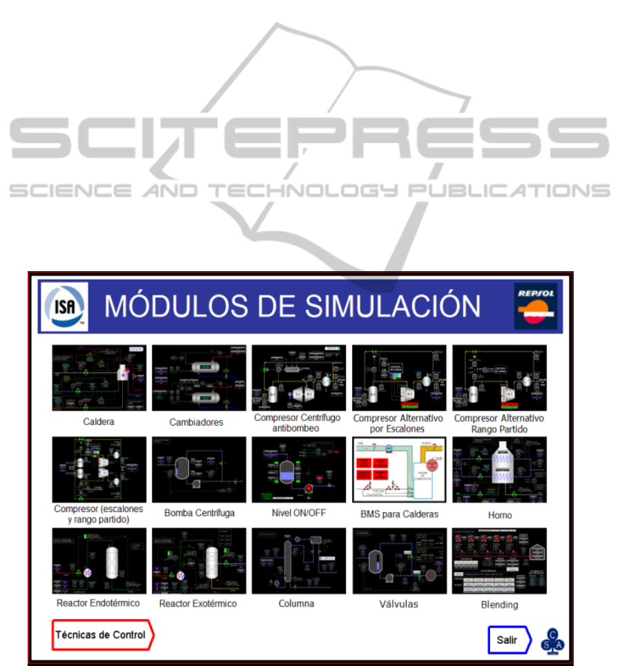
The “Process control units” modules are (Figure 1):
• Steam production boiler. Level and pressure
control (ten coupled control loops).
• Boiler Burner Management System (BMS).
• Exothermic chemical reactor. Hydrodesul-
phurization process control.
Figure 1: "Process control units " menu.
SIMULTECH 2011 - 1st International Conference on Simulation and Modeling Methodologies, Technologies and
Applications
250
• Endothermic chemical reactor. Catalytic re-
forming process control.
• Furnace. Temperature control (eight coupled
control loops) driving two combustibles (fuel
and gas).
• Distillation column. Two control structures and
study of the economic and control aspects
integration.
• Blending. Process control and mixture pres-
cription specification.
• Automatic valves. Characterization of digital
valve positioners.
• Heat exchangers. Cascade and feedforward
compensators.
• Centrifugal compressors. Anti-surge mecha-
nism.
• Alternative compressors. Two control op-tions,
load steps or split-range control.
• Centrifugal pump. Minimum recycling control
of centrifugal pump.
• ON-OFF level controller. Dead band hysteresis
effect and logic controller.
The “Control techniques” modules are:
• Ratio Control. Two options comparative for
products mixture.
• Cascade control. Level tank control using
cascade controllers. Mainly the tuning and the
switching of the manual and automatic mode of
the nested controllers are outlined.
• Selective control. Two cases, case 1 is a
compression station control and case 2 is a
pumping station control. Particular interest in
the anti reset windup mechanism is shown.
• Feed forward control. Temperature control
comparative in a heat exchanger without
feedforward compensator and with a static or
dynamic one.
• Split range control. This technique is applied to
three systems. A pressure control in a
distillation column head, a pressure control in a
blanketing and a simultaneous flow and
temperature control.
When a module is selected, from one of the main
menus, the corresponding dynamic simulator and its
GUI are started. Later, some details about the
simulation are given. Now, the GUI of each module
will be the focus of attention.
The GUI of the selected module corresponds to a
P&ID (ISA, 1992), Piping and Instrumentation
Diagram. These schematics have passive
components that show information as standing or
running equipment indicators, trend and historical
charts, other types of charts (characteristic valve
curves), value displays,... and active components
that allow acting over the system: starting or
stopping pumps, valves or process units; selecting
automatic/manual/cascade mode in controllers;
modifying the boundary condition and the process
and control parameters,...
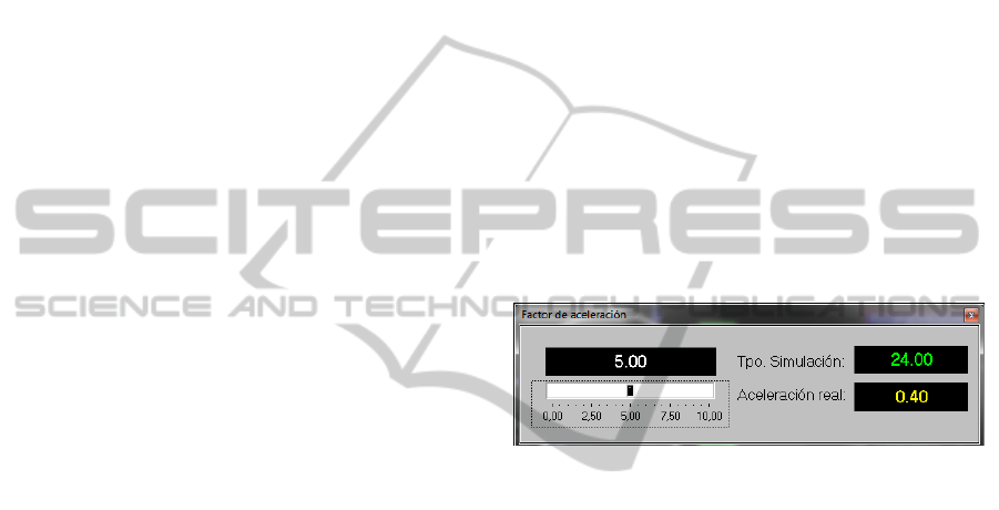
By default the simulation runs in real time, but
the user can change the simulation run speed using a
time factor that can be greater than 1 to accelerate it,
if the PC allows it, or lower than 1 to decelerate it
(Figure 2).
3 EXAMPLE
In order to show how works the simulation tool, one
of the simplest modules has been selected (minimum
recycling control of centrifugal pump). First, a
physical system description and the GUI will be
outlined. Second, an experiment is run.
Figure 2: Time factor.
The system (Figure 3) is composed by a tank that
receives a flow of water, a centrifugal pump
connected to the tank outlet, a recirculation valve
(V1) and an outlet valve (V2). The level controller
(LC1) output is connected, in cascade, with the flow
controller (FC2). The FC2 output drives V2. At the
pump outlet, there are two pipes; one is connected to
V2 and the other one to V1. The recirculated flow
(FI4) is governed by the flow controller (FC1) that
drives V1.
The aim of the control structure is ensure that,
regardless of the LC1 actions, the pumped flow
(FC1) must be always greater that a minimum value
in order to avoid both thermal, mechanical or
electrical problems and the pump cavitation. So, the
Set Point (SP) of FC1 is the minimum pumped flow,
which is a manufacturer specification. All
controllers are implemented by PIDs (Proportional,
Integral and Derivative). The process disturbance is
the external flow to the tank (FI3). Besides, there are
two alarm indicators to high and low level in the
tank. The module allows modifying the PIDs
parameters and observing the control structure
performance when the feed flow changes, in
SIMULATORS FOR CONTROL ENGINEERS ADVANCED LEARNING
251
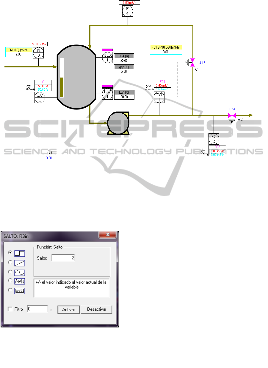
Figure 3: Minimum recycling control of centrifugal pump.
particular when it is less than the minimum pumped
flow.
FI3 and FC1 SP can be modified using a step,
ramp, oscillatory or random signal. The user must
click on the corresponding indicator of the P&ID.
So, an experiment is made in which a step from 5 to
3 m
3
/h in FI3 signal is activated (Figure 4).
Figure 4: Change boundary condition.
Initially, the outlet and pumped flow are equals and
greater than the minimum pumped flow (3.6 m
3
/h) and
therefore V1 is closed and FI4 is zero. As FI3 step result,
FC2 and FC1 will be under the minimum pumped flow
and the controller of minimum flow must act. First,
FI3 decreases from 5 to 3 m
3
/h. The tank level
decreased and LC1 acts decreasing FC2 SP. Conse-
quently, the outlet and pumped flows (in figure 5
FI1 and FI2) decrease simulteneously. When the
pumped flow (FI1) is under the minimum pumped
flow, FC1 acts opening
V1 and, as result, FI4, the
tank level and FI1 are increased and the pumped
flow rises the minimum pumped flow value.
Clicking on the control signals or variables
displays, trend charts showing the performance of
the control structure are shown. These charts can be
configured by the user. Figure 5 shows the flows
performance.
PID controllers implement the main aspects of
the industrial controllers. Pressing the left mouse
button placed on each PID controllers, the GUI for
managing the corresponding PID is shown (Figure
6). The bar graph lets you see (graphically and
numerically) the value of the process variable (PV in
blue), set point (SP in red) and control (OP in
yellow). The user can select the controller mode
(Automatic, Manual or Cascade). In AUTO mode,
he can specify the SP value and, in MAN mode, the
OP value. In manual mode, the user can activate the
SP tracking mechanism to avoid the well-known
“bumpless” of the auto/man controller commutations.
Pressing the “AJUSTE” button the user accesses.
SIMULTECH 2011 - 1st International Conference on Simulation and Modeling Methodologies, Technologies and
Applications
252
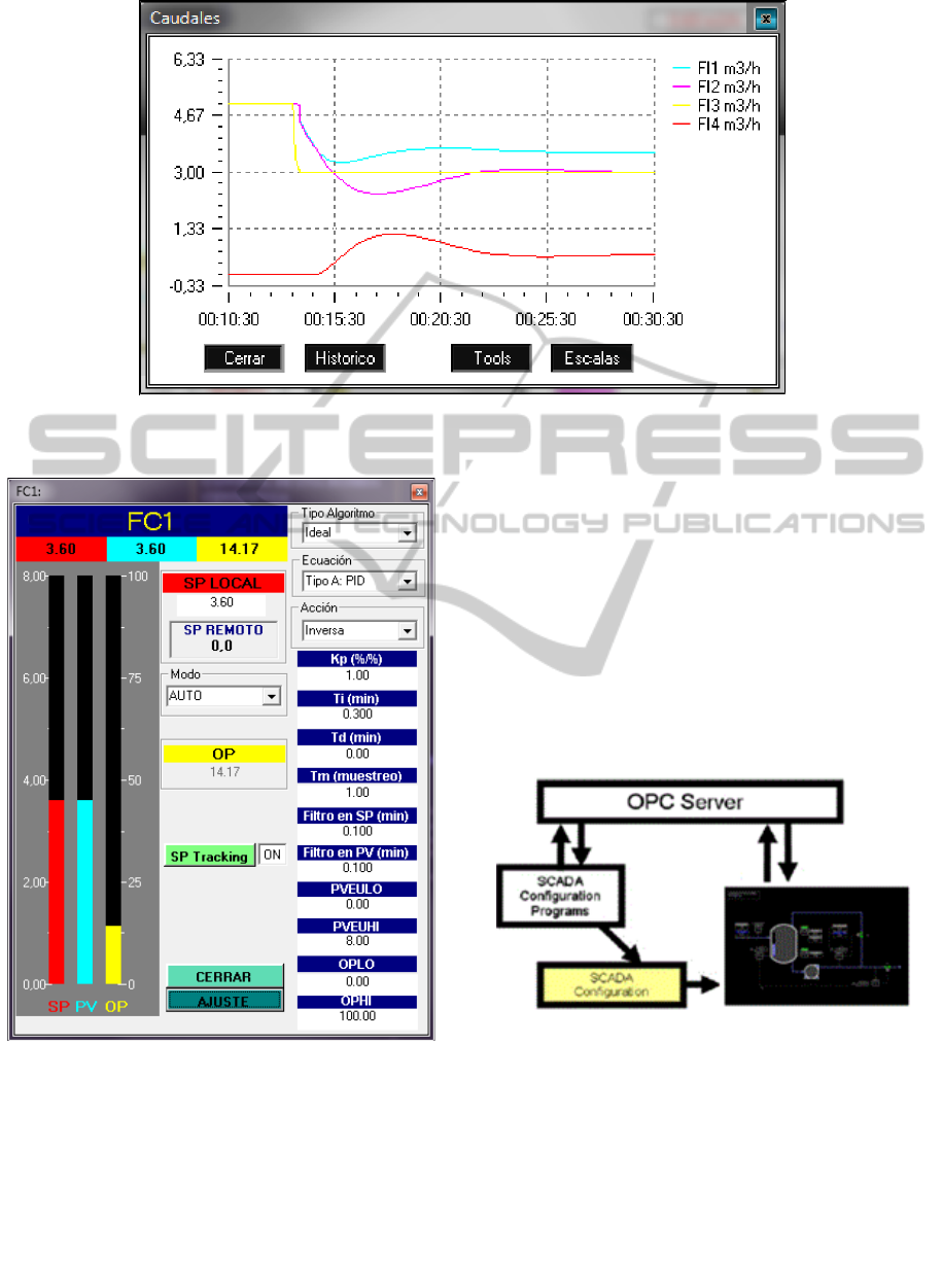
Figure 5: Process and control structure response.
Figure 6: PID interface.
to the tuning parameters (proportional gain, reset
time, derivative time, sampling period, SP and PV
time constant filters, PV and OP span values in
Engineering Units). Additionally, there are three
menus to select the type of algorithm (Ideal or
Interactive), the PID equation (PID, PI-D, I-PD, I)
and the action controller (direct or reverse). The PID
equations use normalized SP, PV and OP values.
4 SOFTWARE STRUCTURE AND
DEVELOPMENT TOOLS
When selecting a particular module a SCADA
system is started. This SCADA is called EDUSCA
(Alves R. et al, 2006) and it is the simulation module
GUI. EDUSCA starts the simulation program linked
to the selected module. The development of each
module GUI involves the EDUSCA setting, which is
done by a drag & drop strategy through a setting tool
(Figure 7).
Figure 7: GUI setting.
The communication between EDUSCA and the
simulation program is performed by the OPC (OLE
for Process Control) communications standard for
process control applications for Windows environ-
ments (OPC Foundation, 2011). EDUSCA acts as an
OPC client and the simulation program as an OPC
server.
The simulation models have been performed
using EcosimPro. EcosimPro belongs to the so
SIMULATORS FOR CONTROL ENGINEERS ADVANCED LEARNING
253
called object oriented modelling languages
(OOML). Many of the EcosimPro characteristics are
similar to the modeling tools that implement
Modelica (Modelica Foundation, 2011). In the sense
that it supports non-causal models able to be
modified automatically according to the context in
which they are used. Its simulation language, called
EL (Ecosimpro Language), allows the description of
process models, named components, in a natural
way by means of continuous differential algebraic
equations and discrete events variables. Each
component can have a ports based interface to
connect to other components.
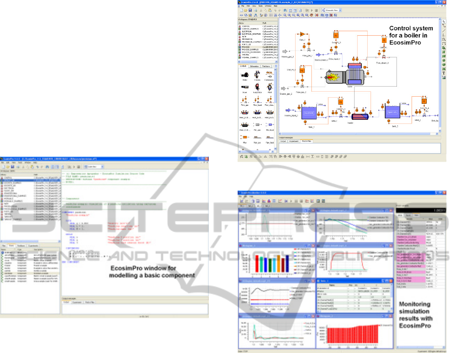
Figure 8: Ecosimpro textual modelling view.
These components are grouped in libraries and
an icon can be attached to each one. The user can
built the system model interconnecting components
by ports, using directly the modeling language) or
the GUI that allows the graphical modeling (Figure
9). Then, the resulting mathematical model is
compiled and, after establishing a partition, that is,
describing which variables constitute the known
boundary conditions, EcosimPro generates the
simulation model that is converted to C++
simulation code linked to the numerical solvers.
Finally, the user runs simulation experiments
from another EcosimPro GUI view (Figure 10).
In this project, two basic model libraries have been
developed, one for process units and another one to
design control structures. The mathematical models
of the process units library components are based on
first principles and the detail of the model is required
for the purpose of the simulator. So, distributed or
globalized parameter models can be found; fast
dynamics can be explicitly modeled or simplified
using static equations; empiric equations can be used
to reduce the model complexity.
The EcosimPro simulation models don’t hold
Figure 9: Ecosimpro graphical modelling view.
Figure 10: Ecosimpro experimental view.
OPC communications. However an OPC server can
be created by adding to the C++ simulation code the
communication routines provided by the OPC
standard. Then, the simulation program is an OPC
server can be accessed from any OPC client. This
process can be automated. In our case, an
application, CreaOPC (Alves R. et al., 2005), creates
OPC servers from the sources files generated by
EcosimPro.
5 CONCLUSIONS
A program with a library of simulation modules of
typical control problems has been briefly exposed.
This library deals with normal control problems
(PID tuning; cascade, feedforward and ratio
control)but, additionally, it includes other type of
control problems (selective, override, split-range
control) and special control strategies to guarantee
security and quality process requirements. A variety
SIMULTECH 2011 - 1st International Conference on Simulation and Modeling Methodologies, Technologies and
Applications
254
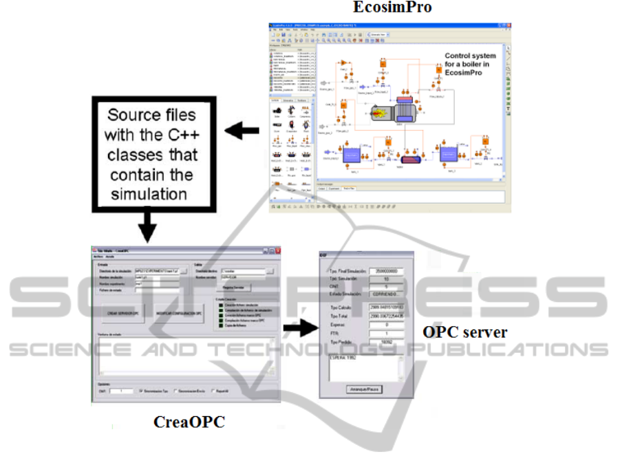
Figure 11: OPC server simulation generation.
of processes are considered, from the simplest ones,
as tanks or heat exchangers, to the more complex
ones, as boilers or distillation columns.
We consider that the program is user-friendly,
few hardware and software resources are required
and the functionality, the level of detail and the GUI
are adapted to the industrial environment and the
learning requirements for control process engineers.
Moreover, it has been validated by experts with
industrial skills. So, it’s used successfully in the
“Master in instrumentation and process control ISA-
REPSOL”.
Finally, to make the simulation based learning
tool for control engineers a diverse set of programs
and EcosimPro libraries have been developed:
• Two complete EcosimPro model libraries of
unit process and control elements. They can be
used to design and test different control
structures to production process.
• EDUSCA: a SCADA and its setting tool.
EDUSCA can be used for different purposes to
the outlined one in this paper. It can access to
any OPC server and, consequently, it can be
used to supervise laboratory plants or any OPC
server simulator.
• CreaOPC, to generate OPC server simulation
programs from the EcosimPro simulation
models. So, the OPC server simulators can be
connected to any OPC client, for instance any
industrial SCADA.
Additionally, as future work, new modules can
be added to the library, for instance a multivariable
predictive control module. Other possible
development and research line is to follow up
EDUSCA to support the web based learning.
ACKNOWLEDGEMENTS
The authors want to express their gratitude to the
ISE (Instituto Superior de la Energía, Fundación
Respsol-YPF) and to the ISA (International Society
of Automation) Spanish Section for the financial and
technical support.
SIMULATORS FOR CONTROL ENGINEERS ADVANCED LEARNING
255

REFERENCES
ABB, 2011. Industrial System 800xA simulator by ABB.
[Online]. Retrieved from http://www.abb.com
Acedo J., 2003. Control avanzado de procesos. Teoría y
Práctica. Ediciones Díaz de Santos. ISBN: 84-7978-
545-4
Acedo J., 2006. Instrumentación y control avanzado de
procesos. Teoría y Práctica. Ediciones Díaz de Santos.
ISBN: 978-84-7978-754-7
ACT, 2011. Topas by ACT. [Online]. Retrieved from
http://www.act-control.com
Alves R. et al., 2005. “OPC based distributed real time
simulation of complex continuous processes”.
Simulation Modelling Practice and Theory. Volume
13, Issue 7, October 2005, Pages 525-549. ISSN:
1569-190X
Alves R. et al., 2006. “EDUSCA (EDUcational SCAda):
Features and applications”. Advances in Control
Education, Volume 7, Part 1. Proceedings of the 7th
IFAC Symposium on Advances in Control Education
Aspentech, 2011. Hysys by Aspentech. [Online]. Retrieved
from http://www.aspentech.com
ControlStation, 2011. LoopPro by ControlStation.
[Online]. Retrieved from http://www.controlstation.
com
Dynasim, 2011. Dymola by Dynasim [Online]. Retrieved
from http://www.dynasim.se
EA, 2011. EcosimPro Dynamic modeling and simulation
tool by EA Internacional. [Online]. Retrieved from
http://www.ecosimpro.com
Honeywell, 2011. UniSim by Honeywell. [Online].
Retrieved from http://hpsweb.honeywell.com
Invensys, 2011. SimSCI-Esscor by Invensys. [Online].
Retrieved from http://iom.invensys.com
ISA-The Instrumentation, Systems, and Automation
Society, 1992. Instrumentation Symbols and
Identification. ISA-5.1-1984 (R1992). Formerly
ANSI/ISA-5.1-1984 (R1992)
Modelica Foundation, 2011. [Online]. Retrieved from
http://www.modelica.org
OPC Foundation, 2011. [Online]. Retrieved from
http://www.opcfoundation.org
Tecnatom, 2011. TEAM_AIDES by Tecnatom. [Online].
Retrieved from http://www.tecnatom.es
VTT, 2011. APROS Process Simulation Software by VTT
Technical Research Centre of Finland. [Online].
Retrieved from http://www.apros.fi.
SIMULTECH 2011 - 1st International Conference on Simulation and Modeling Methodologies, Technologies and
Applications
256
