
NUMERICAL PARAMETRIC STUDY OF COMPLEX LIQUID
FLOW IN THREE-DIMENSIONAL IMPELLER
AND IMPELLER-VOLUTE OF A CENTRIFUGAL PUMP
Massinissa Djerroud, Guyh Dituba Ngoma and Walid Ghie
University of Quebec in Abitibi-Témiscamingue, Department of Applied Sciences
445, Boulevard de l’Université, Rouyn-Noranda, Quebec, J9X 5E4, Canada
Keywords: Centrifugal Pump, Impeller, Volute, Navier-Stokes, Computational Fluid Dynamics, Modeling and
Simulation.
Abstract: In this study, the effects that the blade width, the blade number, and the impeller diameter have on the
steady state liquid flow in three-dimensional impeller, and combined impeller and volute were investigated.
The continuity and Navier-Stokes equations with the k-ε turbulence model and the standard wall functions
were used by mean of ANSYS-CFX code taking into account of the suction pressure variation as a function
of the valve volume flow rate. The achieved results reveal that the selected key design parameters have an
impact on the head, the brake horsepower and the overall efficiency of the centrifugal pump. To valid the
developed approach, the results of numerical simulation were compared with the experimental results
considering a special case of combined impeller and diffuser.
1 INTRODUCTION
Nowadays, centrifugal pumps are widely used in
industrial and mining enterprises. One of the most
important components of a centrifugal pump is the
impeller (Peng, W. W., 2008). The performance
characteristics related to the pump rely a great deal
on the impeller. To achieve better performance for a
centrifugal pump, design parameters such as the
number of blades, blade angles, the blade width, the
blade height, the impeller diameter and the volute
radius must be accurately determined, due to the
complex liquid flow through a centrifugal pump.
This liquid flow is three-dimensional and turbulent.
It is therefore important to be aware of the liquid
flow’s behavior when traveling through an impeller.
This can be done by accounting for the volute in the
planning, design, and optimization phases at
conditions of design and off-design. Many studies
have been carried out on the liquid flow through a
centrifugal pump (Zhou, W. et al., 2003;
Derakhshan, S., et al., 2008; Spence, R., et al., 2008;
Amaral-Teixeira, J., et al., 2008; Cheah, K.W.,
2007; Lee, T. S., et al., 2007; Wen-Guang, L., et al,
2002; LIU, H., et al., 2010; González, J., et al.,
2007; Asuaje, M., et al., 2005; Kaupert, K, et al.,
1999), where the effects of the number of impeller
blades on the pump’s performance were examined
experimentally by Wen-Guang, L., et al, 2002 and
Liu, H., et al., 2010. González, J., et al., 2007 had
numerically investigated the dynamic effects due to
the impeller-volute interaction within a centrifugal
pump, whereas the effects of the volute on velocity
and pressure fields were examined by Asuaje, M., et
al., 2005 and Kaupert, K, et al., 1999. The analysis
of previous works clearly demonstrated that research
results obtained are specific to the centrifugal pump
design parameter values and thus cannot be
generalized. In this work therefore a numerical study
was performed using a finite volume method
according to the CFX code (Ansys inc., 2008) to
gain further insight into the characteristics of the
three-dimensional turbulent liquid flow through an
impeller and a combined impeller and volute
accounting for suction pressure variation as a
function of the valve volume flow rate, while also
considering various flow conditions and pump
design parameters: blade width, blade number and
impeller outer diameters.
2 GOVERNING EQUATIONS
The models selected for the liquid flow in an
93
Djerroud M., Dituba Ngoma G. and Ghie W..
NUMERICAL PARAMETRIC STUDY OF COMPLEX LIQUID FLOW IN THREE-DIMENSIONAL IMPELLER AND IMPELLER-VOLUTE OF A
CENTRIFUGAL PUMP.
DOI: 10.5220/0003566800930102
In Proceedings of 1st International Conference on Simulation and Modeling Methodologies, Technologies and Applications (SIMULTECH-2011), pages
93-102
ISBN: 978-989-8425-78-2
Copyright
c
2011 SCITEPRESS (Science and Technology Publications, Lda.)

impeller and a combined impeller and volute are
depicted in Fig. 1, placing greater emphasis on the
fluid domain.
Fluid domain
a b
Figure 1: Models of a) impeller and b) impeller-volute.
In the governing equations for liquid flow in the
centrifugal pump components, the following
assumptions were made: (i) a steady state, three-
dimensional and turbulence flow using the k-ε
model; (ii) it was an incompressible liquid; (iii) it
was a Newtonian liquid; and (iv) the liquid’s
thermophysical properties were constant with
temperature.
To account for these assumptions, the theoretical
analysis of the liquid flow in an impeller, and a
combined impeller and volute, was based on the
continuity and Navier-Stokes equations (Ansys inc,
2008). For the three-dimensional liquid flow through
the components of a centrifugal pump as shown in
Fig. 1, the continuity equations are expressed by:
0U. =∇
G
,
(1)
and the Navier–Stokes equations are given by:
B))U(U.(p)UU.(
T
eff
+∇+∇∇μ+−∇=⊗∇ρ
GGGG
(2)
where
()()()()
z,y,xw,z,y,xv,z,y,xuUU
G
G
=
is the liquid
flow velocity vector, p is the pressure, ρ is the
density, μ
eff
is the effective viscosity accounting for
turbulence,⊗ is a tensor product and B is the source
term. More particularly, for flows in an impeller
rotating at a constant speed ω, the source term can
be written as follows:
()
(
)
rxxUx2B
G
G
G
G
G
ωω+ωρ−=
(3)
where
r
G
is the location vector.
In addition, μ
eff
is defined as:
teff
μ
+
μ=μ
(4)
where μ is the dynamic viscosity and μ
t
is the
turbulence viscosity.
According to the k-ε turbulence model, μ
t
is linked
to turbulence kinetic energy κ and dissipation ε via
the relationship:
12
t
kC
−
μ
ερ=μ
(5)
where C
μ
is a constant.
The values for κ and ε come directly from the
differential transport equations for turbulence kinetic
energy and turbulence dissipation rates:
ρε−+∇
σ
μ
+μ∇=ρ∇
k
k
t
p]k).[()kU.(
G
(6)
)CpC(
k
]).[()U.(
2k1
t
ρε−
ε
+ε∇
σ
μ
+μ∇=ερ∇
εε
ε
G
(7)
where C
ε1
, C
ε2
and σ
ε
are constants. p
k
is the
turbulence production due to viscous and buoyancy
forces, which is modeled using:
kbt
T
tk
p)kU.3(U.
3
2
)UU.(Up +ρ+∇μ∇−∇+∇∇μ=
G
G
G
G
(8)
ρ∇
ρσ
μ
−=
ρ
.gp
t
kb
(9)
where p
kb
can be neglected for the k-ε turbulence
model.
Moreover, for the modeling of flow near the
wall, the logarithmic wall function is used to model
the viscous sub-layer (Ansys Inc., 2008).
2.1 Impeller
Three velocity types are involved when considering
the flow through a centrifugal pump impeller: the
tangential velocity U = r ω, the relative velocity W,
and the absolute velocity V. The last is expressed in
vector format as follows:
WUV
G
G
G
+=
(10)
Fig. 2 shows the velocity triangles at the impeller
inlet and outlet at the design conditions where the
liquid enters and leaves the impeller at the blade
angles β
b1
and β
b2
. The components of
V
G
and
W
G
in
the direction of
U
G
are V
u,
(swirl velocity), and W
u
,
respectively, while those normal to
U
G
are V
r
and W
r
.
SIMULTECH 2011 - 1st International Conference on Simulation and Modeling Methodologies, Technologies and
Applications
94

Figure 2: Velocity triangles.
Moreover, according to the Euler equation (Peng,
W. W., 2008), the energy transfer per unit mass of
flow for a centrifugal pump can be formulated as:
1u12u2i
VUVUgH
−
=
(11)
where H
i
is the ideal pump total head.
Neglecting the swirl velocity at the impeller inlet,
Eq. 11 can be expressed as follows
2u2i
VUgH =
(12)
When accounting for the hydraulic efficiency, η
h
,
the actual pump head rise is given by:
ih
HH η=
(13)
Also, the hydraulic efficiency can be calculated
using the following empirical formula (Peng, W. W.,
2008):
25.0
h
)Q03.15859( 8.01
−
−=η
(14)
where Q is the volume flow rate in m
3
/s. It is given
by Q = V
r
A with A as the flow passage area normal
to the meridional direction.
Since in reality the flow through a centrifugal
pump is turbulent and three dimensional, the actual
relative flow direction at the impeller exit is
different from that of the blade angle. As depicted in
Fig. 3, the flow angle β
f2
is always less than the
blade angle β
b2.
. This can lead to secondary flows in
the flow passage, from the pump inlet through to
discharge (Peng, W. W., 2008).
Figure 3: Flow angle and blade angle.
As such, the slip factor μ
s
is used to take into
account the difference between β
b2
and β
f2
, which is
formulated as:
'
2u
V
2u
V
s
=μ
(15)
where V
u2
is the actual swirl flow velocity at the
impeller exit and
'
2u
V
is the ideal swirl flow velocity
at the impeller exit.
In addition, the slip velocity is given by:
'
2u2u
WW
2u
V
'
2u
V
s
V −=−=Δ
(16)
Taking into account the slip factor, Eq. 13 can be
expressed as:
⎟
⎟
⎠
⎞
⎜
⎜
⎝
⎛
β
−
⎟
⎟
⎠
⎞
⎜
⎜
⎝
⎛
μη=
22
2
2
sh
tanA
Q
U
g
U
H
(17)
Moreover, to account for the leakage flow from the
impeller, the volumetric efficiency is defined by:
L
L
v
Q
QQ +
=η
(18)
where Q
L
is the leakage flow from the impeller exit
back to the inlet through the clearance.
In addition, the pump’s mechanical efficiency is
formulated as follows:
s
imp
m
P
P
=η
(19)
where P
s
is the brake horsepower and P
imp
the power
delivered by the impeller to the fluid.
P
s
is globally expressed by:
ω=
+
+
+
+
=
CPPPPPPs
dfmLfh
(20)
where C is the pump shaft torque, P
h
is the
centrifugal pump horsepower. It is expressed as:
QgHP
h
ρ
=
(21)
P
f
is the loss power due to the friction, which is
given by:
(
)
HHQgP
if
−
ρ
=
(22)
P
L
is the loss power due to leakage, which is defined
as:
iLL
gHQP
ρ
=
(23)
P
m
is the friction loss power in bearings and seals
and P
df
is the disk friction power due to impeller
shrouds.
NUMERICAL PARAMETRIC STUDY OF COMPLEX LIQUID FLOW IN THREE-DIMENSIONAL IMPELLER AND
IMPELLER-VOLUTE OF A CENTRIFUGAL PUMP
95
P
imp
in Eq. 19 can be formulated as follows:
dfmsimp
PPPP −−=
(24)
Furthermore, Eq. 24 can be rewritten as :
()
iLimp
gHQQP +ρ=
(25)
Accounting for Eq. 24, Eq.19 can be expressed as:
s
dfms
m
P
PPP −−
=η
(26)
Thus, the overall efficiency of a centrifugal pump
can be formulated as:
s
h
P
P
=η
(27)
Finally, the overall efficiency can also be formulated
in terms of the other efficiencies as:
mvh
η
ηη=η
(28)
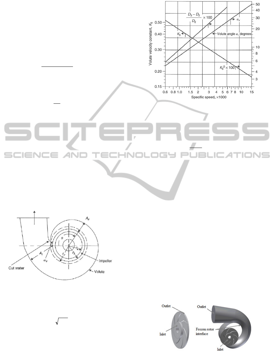
2.2 Volute Parameters
Fig. 4 shows the parameters of a volute defined by
the radius of volute basic circle r
3
, the radius of
volute cut water circle r
v
, the volute angle α
v
, the
volute cross-sectional area A
θ
,which depends of the
angle ϴ, and the volute outlet cross-sectional area A
t
(Peng, W. W., 2008).
Figure 4: Impeller-volute.
The average flow velocity at the volute outlet is
given by:
gH2KV
33
=
(29)
where the volute velocity constant K
3
is an empirical
parameter correlated with the specific speed, as
shown in Fig. 5 along with other volute parameters
such as the volute angle α
v
and the volute basic
circle diameter D
3
.
Figure 5: Volute velocity constant, volute angle and
diameter of volute basic circle versus specific speed.
In addition, the volute cross-sectional area A
θ
can be
formulated as:
c
r
CL2
Q
A
π
θ
=
θ
(30)
where r
c
is the centroid radius of the volute cross-
sectional area, L is the angular momentum of flow at
the impeller outlet which can be expressed by
2u2
VrL
=
. C≅ 0.95 to account for friction loss.
To solve Eqs. 1 and 2 numerically while
accounting for the boundary conditions and the
turbulence model κ-ε, the computational fluid
dynamics ANSYS-CFX code, based on the finite
volume method, was used to obtain the liquid flow
velocity and the pressure distributions. In the cases
examined involving the impeller, and combined
impeller and volute, the boundary conditions were
formulated as follows: the static pressure provided
was given at the inlet, while the flow rate provided
was specified at the outlet. The frozen rotor
condition was used for the impeller-volute interface.
A no-slip condition was set for the flow at the wall
boundaries. Fig. 6 shows the inlet, outlet and
interface domains for the selected centrifugal pump
components.
Figure 6: Domains of inlet, outlet and interface.
Furthermore, the ANSYS-CFX code comprises by
geometry (DesignModeler), CFX-pre, CFX-solver
SIMULTECH 2011 - 1st International Conference on Simulation and Modeling Methodologies, Technologies and
Applications
96
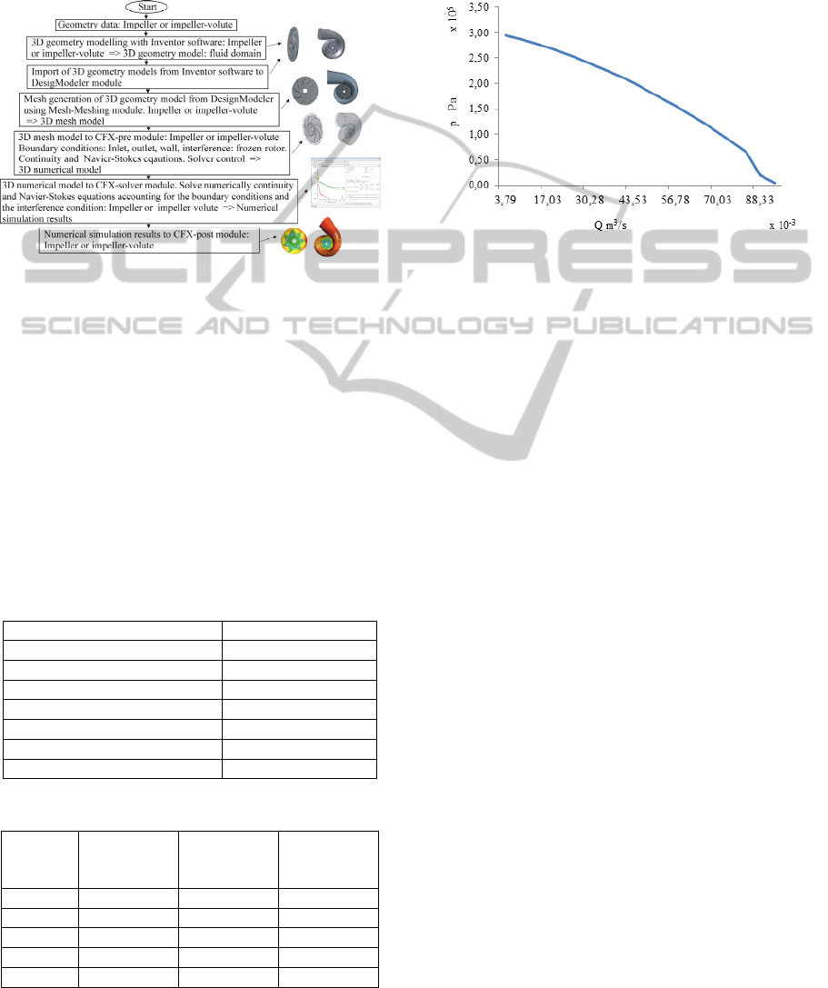
and CFX-post modules. According to the applied
ANSYS-CFX code, Fig. 7 depicts the steps
specifically used to obtain the numerical simulation
results from the geometry models to the numerical
models for the impeller, and the combined impeller
and volute.
Figure 7: Steps from 3D geometry model to numerical
simulation results.
3 RESULTS AND DISCUSSION
Water was used as the working liquid for all
simulations run and for use in this study considered
to have the following reference values: temperature
of 25 °C for water, density of ρ = 997 kg/m³ and
dynamic viscosity of μ = 8.899 x 10
-4
Pa s. The main
data for the reference impeller and volute are given
in Tabs. 1 (Technosub Inc) and 2 (Peng, W. W.,
2008).
Table 1: Main data of the reference impeller.
Inlet diameter [mm] 145
Outlet diameter [mm] 320
Inlet blade angle [°] 11.69
Outlet blade angle [°] 28
Inlet blade width [mm] 12
Blade thickness [mm] 4
Number of blades 7
Rotating speed [rpm] 1800
Table 2: Main data of the reference volute.
Volute
angle [°]
Volute
radius
[mm]
Volute
angle [°]
Volute
radius
[mm]
0 165 225 278.96
45 183.79 270 302.76
90 207.58 315 326.55
135 231.38 360 350.35
180 255.17
Accounting for the fact that the pump rotating speed
was constant, the volume flow rate was controlled
by a regulator valve, which had an influence on the
pressure at the pump inlet, as shown in Fig. 8
(Technosub Inc.). This was accounted for in the
numerical simulations performed.
Figure 8: Pressure at the pump inlet versus valve volume
flow rate regulation.
3.1 Case Studies
Three key design parameters of a centrifugal pump
were selected for an examination of their effects
mainly on the pump performance: impeller blade
width without volute, impeller blade number with
volute, impeller diameter with volute.
3.1.1 Effect of Impeller Blade Width
To investigate the effect that the impeller blade
width has on the pump head, the pump brake
horsepower and the pump overall efficiency, the
blade widths of 4 mm, 10 mm and 15 mm were
selected, while the other parameters were keep
constant. Fig. 9 shows the pump head as a function
of the volume flow rate, illustrating that the pump
head decreases with increased blade width. This is
due augmenting the liquid pressure drop with
increasing blade width. Also, the required pump
brake horsepower decreases when the blade width
rises, as indicated in Fig. 10. The corresponding
overall efficiency curves are shown in Fig. 11,
illustrating that the blade width’s impact on the
overall efficiency is more pronounced in at high
volume flow rates. In other words, the overall
efficiencies for the three blade widths decrease
rapidly to the right side of the best efficiency point
(BEP) and the lowest overall efficiency is obtained
when e = 15 mm.
NUMERICAL PARAMETRIC STUDY OF COMPLEX LIQUID FLOW IN THREE-DIMENSIONAL IMPELLER AND
IMPELLER-VOLUTE OF A CENTRIFUGAL PUMP
97
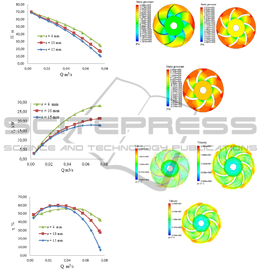
Figure 9: Pump head versus volume flow rate (blade
width).
Figure 10: Pump brake horsepower versus Volume flow
rate (blade width).
Figure 11: Overall efficiency versus volume flow rate
(blade width).
In addition, Figs. 12 and 13 show the static
pressure contour and the liquid flow velocity vector
for Q = 0.065 m
3
/s, illustrating that the static
pressure difference between the impeller outlet and
inlet decreases with increasing blade width, due to
the increase in liquid flow velocity at the impeller
outlet. The average liquid flow velocities at the
impeller outlet are 15.92 m/s, 19.10 m/s and 20.57
m/s for e = 4 mm, e = 10 mm and e = 15 mm,
respectively.
a) e = 4mm b) e = 10 mm
∆P= 3,292 10
5
Pa ∆P= 2,547 10
5
Pa
c) e =15 mm
∆P= 2,056 10
5
Pa
Figure 12: Static pressure contour (blade width).
a) e = 4 mm b) e =10 mm
c) e = 15mm
Figure 13: Liquid flow velocity vector (blade width).
3.1.2 Effect of Impeller Blade Number
When Accounting for Volute
To analyze the effect of the impeller blade number
on the pump head, the pump brake horsepower and
the overall pump efficiency, three impellers whose
blade number were 5, 7 and 9 were selected, while
the other parameters were kept constant. Fig. 14
shows the pump head as a function of the volume
flow rate, illustrating that the pump head increases
with a greater blade number. This is explained by
the decrease in the liquid pressure drop in the flow
passage with an augmented impeller blade number,
keeping the same total volume flow rate. Also, as
SIMULTECH 2011 - 1st International Conference on Simulation and Modeling Methodologies, Technologies and
Applications
98
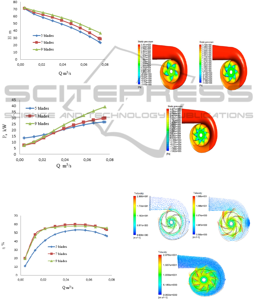
shown in Fig. 15, the pump brake horsepower
increases relative with the augmented blade number.
This is due to the increase in the request pump shaft
torque, as the pump blade number also increases.
Figure 14: Pump head versus volume flow rate (parameter:
impeller blade number).
Figure 15: Brake horsepower versus volume flow rate
(impeller blade number).
In addition, Fig. 16 shows the overall efficiency
curves, showing that the impeller having 5 blades
has the lowest overall efficiency.
Figure 16: Overall efficient versus blade Number (blade
number).
Moreover, Figs. 17 and 18 depict the corresponding
static pressure contour and liquid flow velocity
vector for Q = 0.065 m
3
/s, respectively. These
figures thus clearly show the increased static
pressure difference between the volute outlet and the
impeller inlet relative to the increasing blade
number. This confirms the reduction in the liquid
flow velocity at the impeller outlet relative to the
greater blade number, as represented in Fig. 18
where the average liquid flow velocities at the
impeller outlet were 16.06 m/s, 15.40 m/s et 12.53
m/s for 5 blades, 7 blades et 9 blades, respectively.
a) 5 blades b) 7 blades
∆P = 3,096 10
5
Pa ∆P = 3,60510
5
Pa
c) 9 blades
∆P= 4,223 10
5
Pa
Figure 17: Static pressure contour (impeller blade
number).
a) 5 blades b) 7 blades
c) 9 blades
Figure 18: Vectors of liquid flow velocity contour
(impeller blade number).
NUMERICAL PARAMETRIC STUDY OF COMPLEX LIQUID FLOW IN THREE-DIMENSIONAL IMPELLER AND
IMPELLER-VOLUTE OF A CENTRIFUGAL PUMP
99
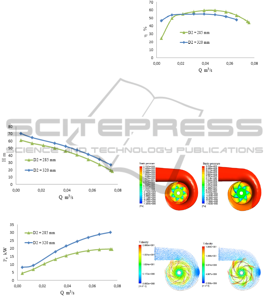
3.1.3 Effect of Impeller Diameter
The impeller outlet diameter values of 285 mm and
320 mm were selected to investigate their effects on
pump performance when keeping the other
parameters constant. Fig. 19 shows that the pump
head increases with increasing impeller diameter,
which can be explained by the fact that the liquid
static pressure drop in impeller decreases with
increasing impeller diameter. In other words, for a
given volume flow rate, the pressure difference
between the volute outlet and the impeller inlet is
higher for an impeller with a greater diameter. In
addition, Fig. 20 shows that the brake horsepower
increases relative to the increasing impeller
diameter, due to the requested augmented impeller
shaft torque relative to the size of the impeller
diameter.
Figure 19: Pump head versus volume flow rate (impeller
diameter).
Figure 20: Brake horsepower versus volume flow rate
(parameter: impeller diameter).
Moreover, the corresponding overall efficiency
curves shown in Fig. 21 indicate that the impeller
having a great diameter has better overall efficiency
with volume flow rates greater than 0.02 m
3
/s.
Figure 21: Overall efficiency versus volume flow rate
(impeller diameter).
Additionally, Figs. 22 and 23 depict the static
pressure contour and the liquid flow velocity vector.
Fig. 22 thus clearly shows the correlation between
the increase in static pressure difference between the
volute outlet and the impeller inlet, and the increase
in the impeller diameter. The average liquid flow
velocities reached at the impeller outlet are 12.51
m/s and 15.40 m/s for D
2
= 285 mm and D
2
=320
mm, as shown in Fig. 23, respectively.
a) D = 285 mm b) D=320mm
∆P= 2,691 10
5
Pa ∆P= 3,386 10
5
Pa
Figure 22: Static pressure contour (impeller diameter).
a) D = 285 mm b) D=320mm
Figure 23: Vectors of liquid flow velocity (impeller
diameter).
3.2 Model Comparison
Since the experimental results of the case of a
combined impeller and diffuser were available from
Technosub Inc., the developed numerical approach
was validated transforming the case of a combined
impeller and volute to a combined impeller and
SIMULTECH 2011 - 1st International Conference on Simulation and Modeling Methodologies, Technologies and
Applications
100
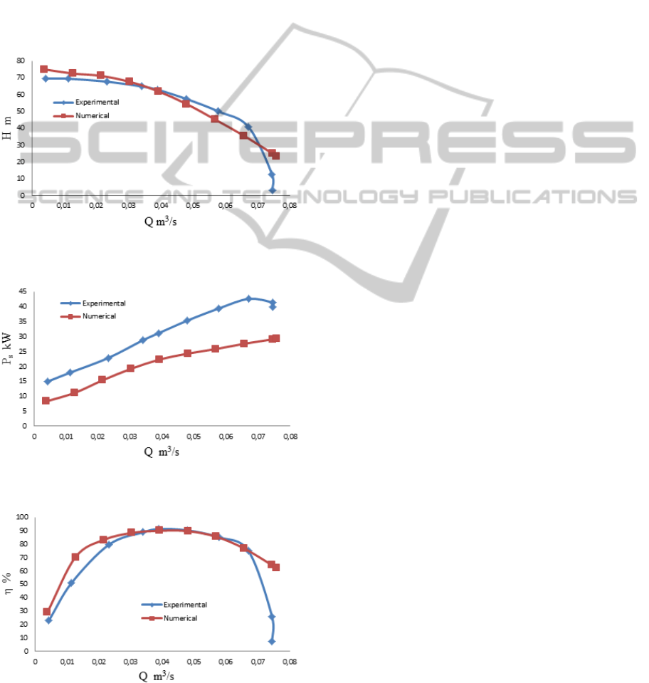
diffuser. When taking into account of experimental
boundary conditions for the numerical simulations
run, Figs. 24-26 show the comparison between the
experimental and the numerical results for the pump
head, the brake horsepower and the overall
efficiency. The discrepancies observed in these
figures could be explained by the fact that lost
mechanical power, power lost due to leakage and the
pump casing were not taken into account in the
numerical simulations carried out. The brake
horsepower for experimental pump brake was
therefore higher than the numerical brake
horsepower obtained, as illustrated in Fig 25.
Figure 24: Pump head versus volume flow rate (numerical
and experimental).
Figure 25: Brake horsepower versus volume flow rate
(numerical and experimental).
Figure 26: Overall efficiency versus volume flow rate
(numerical and experimental).
4 CONCLUSIONS
In this research work, a steady state liquid flow in
three-dimensional impeller, and combined impeller
and volute of a centrifugal pump was numerically
investigated using the ANSYS-CFX code. The
obtained results demonstrate, among others, that the
pump head and the brake horsepower increase with
increasing impeller blade number, while they
decrease with increasing impeller blade width. Also,
the interaction between the impeller and the volute
reveals that the decrease of the impeller outer
diameter keeping the volute dimensions constant
leads to the reduction of the pump head and the
brake horsepower. The pump overall efficiency is
also influenced by the selected parameter. A
relatively good agreement was observed comparing
the developed numerical approach with the
experimental results for special case of the combined
impeller and diffuser. Further research is planned to
develop a generalized numerical approach for
optimizing of combined impeller, diffuser and
volute, accounting for experimental data from pump
manufacturers.
ACKNOWLEDGEMENTS
The authors are grateful to the Foundation of
University of Quebec in Abitibi-Témiscamingue
(FUQAT) and the company Technosub inc.
REFERENCES
Peng, W. W., 2008, Fundamentals of turbomachinery,
John Wiley and Sons. Hoboken, New Jersey.
Zhou, W., Zhao, Z., Lee, T. S. and Winoto, S. H., 2003,
Investigation of Flow Through Centrifugal Pump
Impellers Using Computational Fluid Dynamics.
Intern. J. of Rotating Machinery, 9(1): 49–61.
Derakhshan, S., Nourbakhsh, A., 2008, Theoretical,
numerical and experimental investigation of
centrifugal pumps in reverse operation. Exper.
Thermal and Fluid Sc. 32, 1620–1627.
Spence, R., Amaral-Teixeira, J., 2008, Investigation into
pressure pulsations in a centrifugal pump using
numerical methods supported by industrial tests.
Computers and Fluids 37, 690–704.
Cheah, K. W., Lee, T. S., Winoto, S. H., and Zhao, Z. M.,
2007, Numerical Flow Simulation in a Centrifugal
Pump at Design and Off-Design Conditions. Hindawi
Publishing Corporation International Journal of
Rotating Machinery, Volume 2007, Article ID 83641,
8 pages.
NUMERICAL PARAMETRIC STUDY OF COMPLEX LIQUID FLOW IN THREE-DIMENSIONAL IMPELLER AND
IMPELLER-VOLUTE OF A CENTRIFUGAL PUMP
101

Wen-Guang, L., Fa-Zhang, S. and Cong, X., 2002,
Influence of the number of impeller blades on the
performance of centrifugal oil pumps. World Pumps,
Volume 2002, Issue 427, Pages 32-35.
Liu, H., Wang, Y., Yuan, S., Tan, M., and Wang, K.,
2010, Effects of Blade Number on Characteristics of
Centrifugal Pumps, Chinese j. of mech. eng., Vol. 23,
No. 6.
González, J., Fernández-Francos, J., Blanco, E. and
Santolaria-Morros, C. 2002, Numerical simulation of
the dynamic effects due to impeller-volute interaction
in a centrifugal pump. Transactions of the ASME, J. of
Fluids Engineering, vol. 124, no. 2, pp. 348–355.
Asuaje, M., Bakir, F., Kouidri, S., Kenyery, F., Rey, R.,
2005, Numerical Modelization of the Flow in
Centrifugal Pump: Volute Influence in Velocity and
Pressure Fields. Intern. J. of Rotating Machinery: 3,
244–255.
Kaupert, K. A., Staubli, T. 1999, The Unsteady Pressure
Field in a High Specific Speed Centrifugal Pump
Impeller - Part I: Influence of the Volute. Transactions
of the ASME, J. of Fluids Engineering, Vol. 121, 621-
626.
Ansys inc., 2008, ANSYS-CFX, User Manual, USA.
Technosub Inc., http://technosub.net/.
APPENDIX: NOMENCLATURE
B source term (Nm
-3
)
b height (m)
d diameter (m)
e width (m)
g acceleration of gravity (ms
-2
)
H head (m)
P power (W)
p pressure (Nm
-2
)
p
κ
turbulence production due to viscous and
buoyancy forces
Q volume flow rate (m
3
s
-1
)
r radial coordinate (m)
V absolute velocity (ms
-1
)
v flow velocity in y direction (ms
-1
)
U velocity or tangential velocity (ms
-1
)
u flow velocity in x direction (ms
-1
)
W relative velocity (ms
-1
)
w flow velocity in z direction (ms
-1
)
x x-coordinate (m)
y y-coordinate (m)
z z-coordinate (m)
Greek symbols
α angle between V and U (°)
β blade angle between W and U (°)
Δ difference
ε turbulence dissipation (m
2
s
-3
)
η efficiency
κ turbulence kinetic energy (kg m
-2
s
-2
)
θ angle (°)
ρ fluid density (kg m
-3
)
μ dynamic viscosity (Pa s)
μ
eff
effective viscosity (Pa s)
μ
s
slip factor
μ
t
turbulence viscosity (Pa s)
ω angular velocity (rad s
-1
)
Subscripts
1 inlet
2 outlet
3 volute outlet
b blade
df disk friction
f flow
h hydraulic
i inlet or ideal
imp impeller to fluid
L leakage
m mechanical
o outlet
r radial or perpendicular to the vector U
s shaft or slip
u direction of vector U
v volumetric or volute
w wall
SIMULTECH 2011 - 1st International Conference on Simulation and Modeling Methodologies, Technologies and
Applications
102
