ARCHITECTURE FOR ENVIRONMENTAL DATA ACCESS IN WSN
J. M. Mora-Merchan, F. J. Molina, D. F. Larios, G. Rodriguez, J. Barbancho and C. Le´on
Department of Electronic Technology, University of Seville, University School Polytechnics, Seville, Spain
Keywords:
WSN, Software Architecture, Hardware Architecture, Weather Monitoring.
Abstract:
This paper shows different issues found in the real implementation of either a WSN or its data exploitation
system for an environmental monitoring application. A generic software architecture for interfacing both is
proposed and tested on a real case.
1 PROBLEMS OF INTERFACING
WITH WSNS
Most papers about Wireless Sensor Networks
(WSNs) do not include information about accessing
data from external applications.
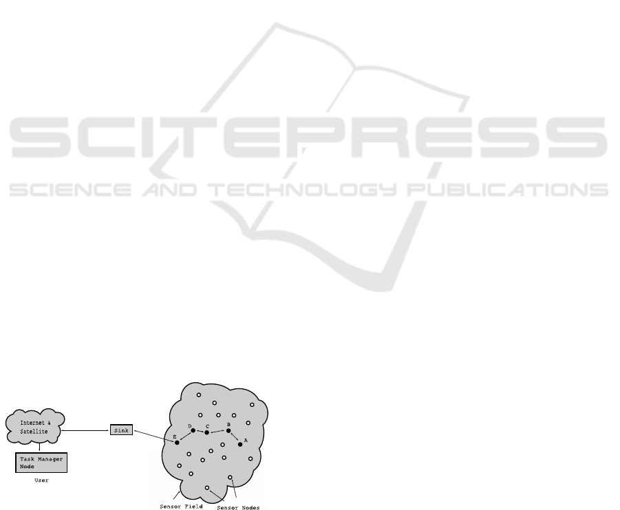
Usually, articles present the interface as a ‘sink”
without mentioning its internal architecture or how
it provides information to remote machines, applica-
tions or users. Figure 1 shows one of these schemes
(taken from (Akyildiz et al., 2002)). Generally, sci-
entific research is focused on WSN topology, mesh
types or node characteristics, but there is a lack of in-
formation about the data flow between the the Base
Station and the information system.
Figure 1: Typical architecture description (copy from (Aky-
ildiz et al., 2002)).
The developmentand further implementation of a real
WSN and an Information System require answering
the following questions:
• How to connect the Sensor Field to the Sink.
• How to pre-process to validate information re-
ceived, and
• How to store retrieved information.
Firstly, one involves the router needed to intercon-
nect WSN and more practical networks like Internet.
For this, it is necessary to define hardware and soft-
ware communication protocols. The second question
defines how to detect invalid data and how to fix it, if
possible. Unlike other networks, WSNs routings are
not always reliable. No packets, multiple copies of the
same one, or corrupted packets arrive at the Base Sta-
tion. Finally, the third question looks for an efficient
data storage to allow us to keep the needed data and
an easy way of retrieving information. The designing
and the implementation of a WSN require finding a
solution for all these questions.
The following section (sec. 2) describes the hard-
ware of the network we are working with. In section
3, a generic software architecture is proposed, and a
real implementation is described. Finally, we summa-
rize the main conclusions and future work.
2 ICARO NETWORK
On April 8th, 2010 a WSN was deployed in Do˜nana
Biological Reserve (DBR). Do˜nana Biological Re-
serve is considered one of the most important natural
protected landscapes in the world: 543 km
2
, of which
135 km
2
are a protected area. In 1994 UNESCO des-
ignated it a World Heritage Site and the park was rec-
ognized as a Biosphere reserve. DBR is located in the
southwest of Andalusia (Spain).
The network, called Icaro, was devised as a pi-
lot of environmental measurements and distributed
computation. Its purpose is to serve as a real test-
ing ground. It allows us to check our simulations in
real conditions. Icaro lets us measure interactions not
considered in theoretical models.
102
M. Mora-Merchan J., J. Molina F., F. Larios D., Rodriguez G., Barbancho J. and León C..
ARCHITECTURE FOR ENVIRONMENTAL DATA ACCESS IN WSN.
DOI: 10.5220/0003542301020106
In Proceedings of the International Conference on Data Communication Networking and Optical Communication System (DCNET-2011), pages 102-106
ISBN: 978-989-8425-69-0
Copyright
c
2011 SCITEPRESS (Science and Technology Publications, Lda.)
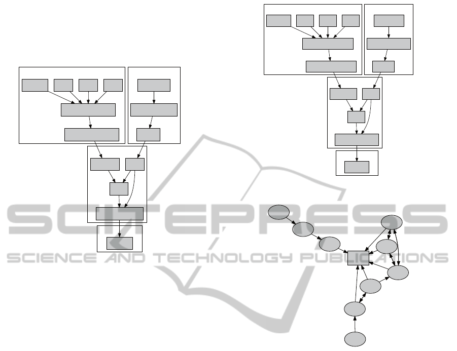
Each node in Icaro is a stand alone system capable
of running as an independent entity or within a collab-
orative network. It is made up of 4 functional blocks
shown in figure 2: Sensors, Power Supply, Processing
Unit and Communications.
!
"
#
Figure 2: Node Hierarchy.
Sensor Block is the interface with the environ-
ment. Sensors are integrated in a commercial weather
station (Davis Vantage Vue (Davis Instruments, nda))
which captures temperature, atmospheric pressure,
humidity, rain rate, wind velocity and direction. It
contains a custom module for serial communications
(Davis WeatherLink 6510SER (Davis Instruments,
ndb)) to transfer information to the Processing Unit.
In the Power Supply block, a 12 V 6 Ah battery stores
and distributes energy harvested by a 10 W solar
panel.
A Crossbow TelosB mote (Crossbow, nd) is the
core processing unit. It is an inexpensive platform
which has an integrated radio transceiver and an ac-
cessible serial port. TelosB is a platform supported
by TinyOS (Levis et al., 2005) operating system, It is
very popular and well tested by the research commu-
nity on WSN applications. TinyOS provides a com-
munication stack and manages access to peripherals.
This simplifies the development of new algorithms.
For the communications, TelosB includes a
transceiver. To increase radio range, we have added
an external omnidirectional antenna.
Figure 3 shows a real installed node in Do˜nana.
The pole holds the weather station, the solar panel,
antenna, and a sealed box with the rest of the compo-
nents.
Icaro topology is shown in figure 4. Ten nodes
and a base station make up the Icaro network. The
arrows in the figure represent the routes that packets
can follow to the Base Station. The topology has been
!
"
#
Figure 3: Real Icaro Node.
Figure 4: Icaro Topology.
designed to test different cases (Stinnett, 2007)(Pa-
trikar and Akojwar, 2008)(Thouvenin, 2007): Pure
multi-hop routes (nodes 5, 6 and 7), pure all-to-all
nets (nodes 2, 3 and 10, and nodes 8 and 9) and hybrid
combinations (nodes 4, 8, 9 and 10).
Base Station is a node with a Moxa embedded in-
dustrial PC (Moxa, nd) connected to TelosB by USB.
TelosB software of Base Station collects data from
network and re sends to the PC. This PC acts as a
bridge between WSN and Internet.
3 SOFTWARE ARCHITECTURE
FOR THE INTERFACE BLOCK
3.1 General Architecture
We proposean architecture (fig. 5) for interfacing data
collected in a WSN to final applications. As men-
tioned, this interface is usually overlooked in scien-
tific papers, and it should be part of a general scheme.
ARCHITECTURE FOR ENVIRONMENTAL DATA ACCESS IN WSN
103
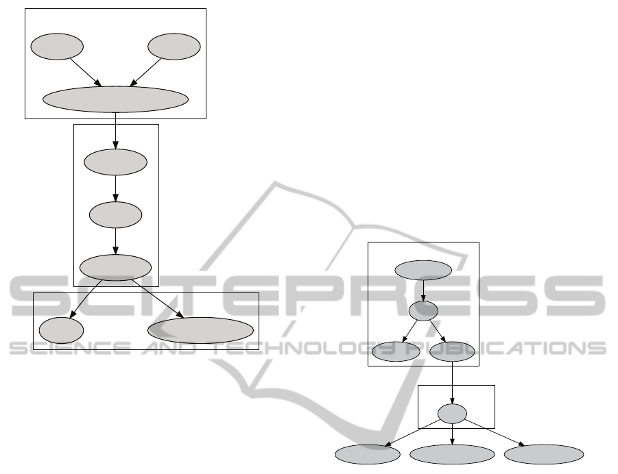
Figure 5: General Architecture.
WSN is a sensor field where nodes are data
sources which provide raw data, processed data and
metadata. Raw data are direct measurements of the
sensors. Processed data are the result of individual
or collective distributed processing of several nodes,
and metadata facilitate data interpretation like times-
tamps, geographic information, data range, etc.
In our model, processing algorithms are consid-
ered as virtual sensors with the same logic internal
structure and methods of the real sensors. In fact, they
can associate metadata to the processed data.
Depending on the application, results of collabo-
rative processing may be assigned to the area covered
by the involved sensors. In these cases, virtual nodes
must be created using special node identifiers, global
information, such as time, and area-related parame-
ters. With this approach, all data management from
Base Station to application level is homogeneous, no
matter the origin of the data.
Interface Software Architecture is made up of
three software components: router, filter, and storage.
The router translates the data frames from WSN
to a more suitable one, and it must open a TCP server
socket. In this way, multiple clients can access the
data stream, no matter if they are in the same host
machine.
In order to test all wireless traffic, the router will
resend all incoming communication frames, not only
sensor data frames. The filter component is highly
dependent on the WSN application, and it must often
be customized to select the right sensor data, and to
remove corrupted or duplicated data.
Storage component saves either filtered on unfil-
tered data to facilitate data retrieval, tracing and de-
bugging.
3.2 Icaro Interface Software
Architecture
Icaro implements a customized architecture of the
general model (fig. 5). It consists of independent
modules so that it is possible to improve the system
replacing one or more modules. Figure 6 shows the
real structure of Icaro.
Figure 6: Software Architecture of the Interface.
The interface functionality is divided into the Base
Station Computer and Application Computer. Base
Station Computer is a Moxa industrial embedded PC
with a TelosB mote plugged in a USB port. The sec-
ond computer is a remote Database (Mysql) placed in
our laboratory.
The WSN data are timestamped and geographic
information is coded in the node identification. Fur-
thermore, Icaro runs an auto-organized neural algo-
rithm to process different environmental measure-
ments (temperature, humidity, atmospheric pressure,
etc) in el Ojillo marsh to learn predicting water level
changes. The result of data processing also includes
metadata with current time and debugging informa-
tion (e.g. local winning neuron).
Base Station Node delivers all data to the com-
puter host by mean of a well known TinyOS sniffer
called basestation. The interface component receives
all information from nodes at the entry point of the
Router component. In Icaro, a TinyOS tool called Se-
rial Forwarder (sf) implements this function.
Serial Forwarder protocol is very simple: A one
byte header with the length of message and the mes-
DCNET 2011 - International Conference on Data Communication Networking
104
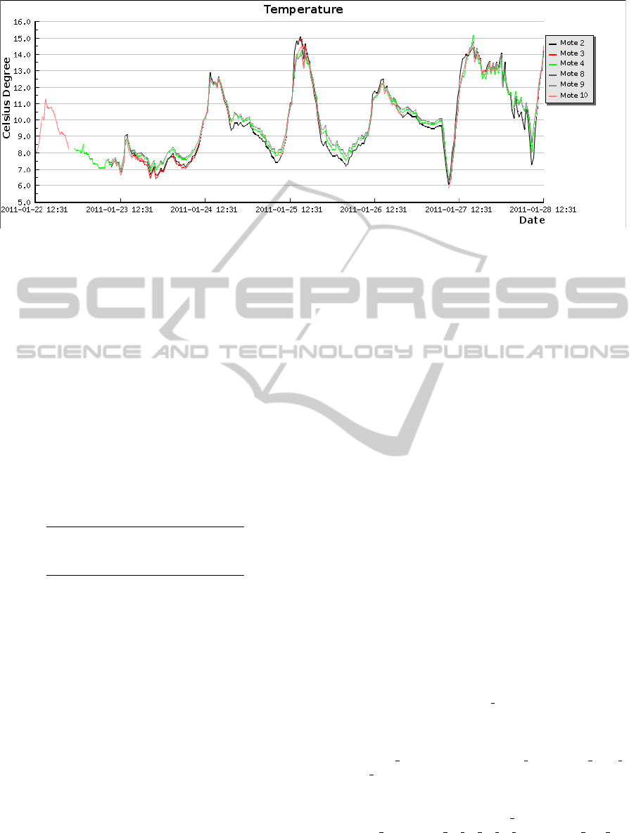
Figure 7: Example of captured data.
sage. There is no error control.
hheader : length(1 byte)ihpayload : datai
Data stream is sent from serial forwarder to a log
registry and a filter application. The registry is a time
limited copy for data frame debugging. In Icaro, the
filter just removes non valid data (i.e. corrupted or
duplicated) because of the lack of error control in se-
rial forwarder protocol. A parser in the filter analyzes
frames and looks for valid structures in the payload.
The filter must check for multiple copies of the same
message before uploading data to the DB. Table 1
shows error statistics based on a sample of 1300 cases.
Table 1: Detected errors in Parse time.
Valid data frame 92.2 %
Corrupted data frame 3.5 %
Duplicated data frame 4.3 %
The Application Server contains a database (DB)
to connect with different applications to analyse data:
e.g graph visualisation tools, Protocol analysers, Data
Mining utilities or any other customized application.
Database offers an common interface to makethe data
more accessible.
4 RESULTS AND FUTURE WORK
Designing a generic data exploitation system of a
WSN is a non trivial and open problem. Most of im-
plemented systems are application-specific.
In this paper, we present a first draft of a general
software architecture to interface WSN and remote
applications. A real implementation is also included
to support a smart environmental application.
Icaro Net has been working since 2010. It has
more than 1 GigaByte of environmental measure-
ments. Figure 7 is a sample of temperature evolution
for a week.
After analyzing the data exploiting system, we can
point out the following topics to work on in the future:
• Descriptions of WSN data and metadata should be
standardized, probably using a specific extension
of XML.
• Virtual nodes created to represent collaborative
processing results are a special sort of metadata
that deserve specific attention.
• Because of specific data format in WSN applica-
tions, an automatic parser generation tool will be
useful to implement new filters.
• Database time scalability. Database size is contin-
uously growing, making data access less efficient.
REFERENCES
Akyildiz, I. F., Su, W., Sankarasubramaniam, Y., and
Cayirci, E. (2002). Wireless sensor networks: a sur-
vey. Computer Networks, 38:393 – 422.
Crossbow (n.d.). Telosb datasheet. http://
www.willow.co.uk/TelosB Datasheet.pdf. [Accessed
20 Febrary 2011].
Davis Instruments (n.d.a). Vantage Vue Weather Sta-
tion. data sheet. http://www.vantagevue.com/
product documents/weather/spec sheets/6250 6351
57 SS.pdf. [Accessed 20 Febrary 2011].
Davis Instruments (n.d.b). Weather Link for Van-
tage Pro and Vantage Pro2 datasheet. http://
www.vantagevue.com/product documents/weather/
spec sheets/6510 40 44 50 60 SpecWLWin Rev D.
pdf. [Accessed 20 Febrary 2011].
Levis, P., Madden, S., Polastre, J., Szewczyk, R., White-
house, K., Woo, A., Gay, D., Hill, J., Welsh, M.,
ARCHITECTURE FOR ENVIRONMENTAL DATA ACCESS IN WSN
105

Brewer, E., and Culler, D. (2005). Tinyos: An op-
erating system for sensor networks. In Weber, W.,
Rabaey, J. M., and Aarts, E., editors, Ambient Intel-
ligence, pages 115–148. Springer Berlin Heidelberg.
Moxa (n.d.). V2101 series datasheet. http://
www.moxa.com/support/search result.aspx?prod id=
726&type id=5&cat type=doc. [Accessed 20 Febrary
2011].
Patrikar, R. M. and Akojwar, S. G. (2008). Neural net-
work based classification techniques for wireless sen-
sor network with cooperative routing. In Proceedings
of the 12th WSEAS international conference on Com-
munications, pages 433–438, Stevens Point, Wiscon-
sin, USA. World Scientific and Engineering Academy
and Society (WSEAS).
Stinnett, J. (2007). The COMPASS multihop framework for
tinyos. Technical report, Rice University.
Thouvenin, R. (2007). Implementing and evaluating the dy-
namic manet on-demand protocol in wireless sensor
networks. Master’s thesis, University of Aarhus De-
partment of Computer Science.
DCNET 2011 - International Conference on Data Communication Networking
106
