
AN OPTIMAL ADMITTANCE REACTIVE FORCE CONTROL FOR
COOPERATIVE ROBOT GRASPING TASKS
A. Rodriguez-Angeles, R. de J. Portillo-Velez and C. A. Cruz-Villar
Center for Research and Advanced Studies, CINVESTAV-IPN
Av. Instituto Politecnico Nacional No. 2508, Col. San Pedro Zacatenco, C.P. 07360, Mexico City, D.F., Mexico
Keywords:
Admittance, Optimization, Interaction, Grasping, Cooperation.
Abstract:
In this article it is proposed an optimal admittance algorithm that controls the position of the end effectors in
cooperative robot systems or fingers, in case of robotic hands, reactively according to on-line force sensory
data. The method is free of in-depth models or sophisticated external sensors. The sensors used are simple and
provide only limited and immediate information, nonetheless they allow to reactively correct the applied force
to guarantee object stable grasp. Force sensory information is used to determine modification of the desired
movement of the robots at a cooperative system, so that ultimately the applied force to guarantee a stable
object grasp is achieved. The proposed optimization algorithm uses force error at each robot as a correction
factor when calculating a modified Cartesian desired trajectory, thus it results on real time reactive motion
planning. The novelty of the proposed algorithm is that the adaptive admittance controller is obtained as the
solution of a dynamic optimization problem which is solved via the standard gradient flow approach. The
proposed methodology considers grasps and fixtures whose contacts react according to force displacement
laws consistent with friction constraints at the contact points. It is only assumed that each robot end effector is
capable of generating its own linear force displacement. Experimental results show that the proposed controller
is robust against environmental stiffness uncertainties and its variations, as well as object position uncertainty,
as far as an initial contact between the robots and the object is guaranteed.
1 INTRODUCTION
Traditionally, robot control uses either position con-
trol or force control (or a combination of both modes).
In contrast, intuitive control also considers the actual
task to be performed (Pratt and Pratt, 1998; Duchaine
and Gosselin, 2009); this leads to a disappearing of
the former strict distinction between planning, reac-
tive planning and reactive control. Combining reac-
tive, stimulus-response control with cognitive, pre-
planned behavior government, results in robust, flexi-
ble, autonomous, real-time robot control (Yigit et al.,
2003).
A reactive algorithm means a simple algorithmic
scheme where robot sensors determine immediately
the actions of the actuators. However, note that the ac-
tuators themselves may interact with the sensors (e.g.
by moving them or occluding them, etc.) to close a
feedback loop and thus cause further goal-driven as
well as corrective actions, (Teichmann and Mishra,
2000). Reactive systems present the features of liv-
ing entities such as real time response, robustness and
ability to exploit the environment. Reactive architec-
tures rely on the stimulus-response principle. It con-
sists in rules defining the actions/behaviors which can
be released following the perceived state of the envi-
ronment (Simonin, 2006). Reactiveness is relevant for
autonomous cooperative tasks such as spatial coordi-
nation and grasping. However, considering industrial
applications, some drawbacks must be reported (Si-
monin, 2006): 1.- strong dependence to perception
(quality and nature of percepts); 2.- sensors perturba-
tions due to environmental conditions (changes); 3.-
internal parameters such as weights for actions selec-
tion may be difficult to define (can need a learning
process).
Dexterous manipulation and grasping commonly
assume an accurate model of the object to be grasped
and, from such a model, an off-line geometric algo-
rithm determines a set of grip points, where the end
effectors or fingers are then placed. Over the last
years, several approaches have been proposed to the
problem of grasp determination, many of them based
on predefined models of objects or requiring expen-
sive computation, e.g. (Sanz et al., 1999; Roa and
Suarez, 2009).
50
Portillo-Velez R., Rodriguez-Angeles A. and A. Cruz-villar C..
AN OPTIMAL ADMITTANCE REACTIVE FORCE CONTROL FOR COOPERATIVE ROBOT GRASPING TASKS.
DOI: 10.5220/0003536600500058
In Proceedings of the 8th International Conference on Informatics in Control, Automation and Robotics (ICINCO-2011), pages 50-58
ISBN: 978-989-8425-75-1
Copyright
c
2011 SCITEPRESS (Science and Technology Publications, Lda.)

The pre-planned grasp analyses the object to be
grasped and decides where the contacts should be
placed before any action is carried out. The grasp
selection (or grasp planning) task can be broadly de-
fined as follows: given an object to be acquired us-
ing a grasping system, find a combination of posture
and position relative to the object that results in a sta-
ble grasp that is likely to resist expected perturbations
(Shapiro et al., 2010).
Typically, once the grip points have been deter-
mined, the geometry of the object is deemed irrele-
vant and the grasp is determined and maintained by
only controlling the magnitudes of the forces at the
grip points. This approach has provided a clear and
deep understanding of stable grasp, how their exis-
tence depends on the nature of contact and the physi-
cal complexity of grasping, and so on. Nevertheless,
this approach has proved to be less useful in practice,
as obtaining an accurate model of the object might not
be feasible, the exact location of the object might not
be available, poor robot repeatability, or imprecise in-
verse kinematics, see (Teichmann and Mishra, 2000;
Vahrenkamp et al., 2008).
Here the proposed approach is motivated by ordi-
nary human−human interactions. As the awareness
of a person of the motion of another person allows
for a mental prediction of the future motion and pre-
ventive action, including such an ability in the con-
trol strategy of an interactive robot can significantly
improve its effectiveness toward cooperative and col-
laborative tasks. Our results show that in cooperative
robot grasping, reactive force control can correct for a
fair amount of uncertainty on the object position and
its stiffness, which results on real time motion plan-
ning. Based on the measured robot-object interaction
force, our algorithm locally modifies a nominal path
so to achieve the desired contact force, in more so-
phisticated strictly cooperating tasks, to reach the cor-
rect rendezvous between the robot end-effector and,
say, the object, to guarantee a stable grasp.
Several reactive motion planning approaches ex-
ist in this context, mostly based on artificial poten-
tial fields and their algorithmic or heuristic (Khatib,
1986; Brock and Khatib, 2002; Santis et al., 2008).
Another method considers the on−line generation of
the Cartesian path of multiple control points on the
manipulator. Alternatively, the so called admittance
control has been also used for reactive planning, such
that it modifies the robot trajectory in order to achieve
some desired force at some direction (Santis et al.,
2006). Despite of the success and simplicity of the
admittance approach, most of the proposed solutions
require a priori knowledge of robot and/or the object
dynamics, which limits their potential applications
(Teichmann and Mishra, 2000; Hsiao et al., 2010).
Furthermore, some factors as geometric uncer-
tainty may lead to excessive forces (Chiaverini et al.,
1999), which possibly overcome safety by causing
damage to the robot structure or the object. Thus,
adaptation schemes are chosen as an alternative so-
lution to deal with uncertainty and to guarantee safe
robot-object interaction. Nevertheless, when adapta-
tion approaches are considered most of the times di-
rect force measurement is needed. These schemes are
referred as direct or explicit methods (Colbaugh and
Glass, 1997; Seraji and Colbaugh, 1997). Other meth-
ods use estimates of the parameters of the robot and/or
the object. Such methods are denominated indirect
or implicit methods (Seraji, 1998; Jung et al., 2001).
The methods described above have been proved to
be effective, nonetheless they require a considerable
amount of computations.
In this paper, an optimal admittance controller is
proposed to ensure the desired pre-planned applied
force to guarantee a stable object grasp by a coopera-
tive robot system. The novelty of the proposed algo-
rithm is that the admittance controller is obtained as
the solution of a dynamic optimization problem which
is solved via the standard gradient flow. The optimiza-
tion problem considers the force error tracking and its
time derivative. It is important to highlight the simple
structure of the proposed admittance controller. The
reference trajectory of each robot at the cooperative
system is computed very fast, yielding on-line reac-
tive motion planning of the robots end-effector tra-
jectory to uncertain forces, which may arise during
object interaction. This fast adaptation results in safe
robot-object interaction by guaranteeing application
of the desired pre-planned grasping interaction force.
On the other side, it is well known that it is not advis-
able to use the force error time derivative, because it
is a highly noisy signal. However, the proposed ap-
proach allows to manage signals with noise, thanks to
the filtering properties of the time integration, which
is used because of the gradient flow approach.
2 COOPERATIVE ROBOT
SYSTEM
The problem faced in this papers reads as follows: to
design an optimal admittance controller to perform
stable robot-object grasping by a cooperative robot
system in a reactive framework.
It is important to highlight that the compliance ap-
proach to robot force control is used, which can be
viewed as unconstrained motion control. Thus, all
control methods for unconstrained motion, such as
AN OPTIMAL ADMITTANCE REACTIVE FORCE CONTROL FOR COOPERATIVE ROBOT GRASPING TASKS
51
PID control, sliding mode control and model based
control, can be used.
First the robots and object models related to the
proposed approach are introduced. It is assumed fully
actuated robots whose working space cover the re-
quirements for the Cartesian task (grasping).
2.1 Kinematic Model
Consider n
i
-joint fully actuated rigid robots, non nec-
essarily identical, where i = 1,.., p identifies the p
robots which conform the cooperative system, see
Figure 1. The robot joint variables are denoted by
q
i
∈ ℜ
n
i
. In general terms, the direct kinematics re-
lates the joint variables, q
i
, and the i− th robot end-
effector Cartesian variables, X
i
∈ ℜ
m
i
, all of them
with respect to a general Coordinate system. It is con-
sidered that the Cartesian working space dimension
m
i
of each robot is at least equal to the task working
space T
s
, i.e. T
s
≤ m
i
∀i = 1,..., p, such that it guaran-
tees that all robots might execute the Cartesian task.
The direct kinematic model of the i−th robot ma-
nipulator can be expressed as
X
i
= F
DK,i
(q
i
) (1)
To fully relate the joint and Cartesian spaces of
the i− th robot manipulator, it is required to establish
a relation among robot joint velocities,
˙
q
i
∈ ℜ
n
i
, and
the i−th end-effector Cartesian velocities,
˙
X
i
∈ ℜ
m
i
.
For this, it is considered the robot Jacobian as follows
J
i
(q
i
) =
∂F
DK,i
(q
i
)
∂q
i
∈ ℜ
m
i
×n
i
(2)
2.2 Dynamic Model
Applying the Euler-Lagrange formalism, the joint
space dynamic model of the i − th robot manipulator
is given by
M
i
(q
i
)
¨
q
i
+C
i
(q
i
,
˙
q
i
)
˙
q
i
+ F
c,i
˙
q
i
+ G
i
(q
i
) = τ
i
+ J
T
i
(q
i
)F
i
(3)
where M
i
(q
i
) ∈ ℜ
n
i
×n
i
is the symmetric, positive-
definite inertia matrix, G
i
(q
i
) ∈ ℜ
n
i
, denotes the vec-
tor of gravity forces, F
c,i
˙
q
i
∈ ℜ
n
i
, is the viscous fric-
tion effects, with F
c,i
a diagonal matrix containing the
viscous friction coefficients of the i − th robot ma-
nipulator joints. The vector,C
i
(q
i
,
˙
q
i
)
˙
q
i
∈ ℜ
n
i
, repre-
sents the Coriolis and centrifugal forces and the vec-
tor of input torques for the i − th robot manipulator
is τ
i
∈ ℜ
n
i
. The vector F
i
∈ ℜ
m
i
represents the i− th
robot-object interaction force.
Figure 1: Cooperative system.
2.3 Robot-object Interaction Force
Typically, the object reaction force model is repre-
sented as a simple linear spring. Hence the i − th
robot-object interaction force depends on its end ef-
fector Cartesian position related to the object position
at the contact point, and it is given by
F
i
= K
o,i
(X
i
− X
o,i
) if X
i
≥ X
o,i
(4)
where K
o,i
∈ ℜ
m
i
×m
i
represents the stiffness at the
contact point between the i − th robot end effector,
or the force sensor in case it is mounted at the end ef-
fector, and the object. X
o,i
∈ ℜ
m
i
is the position of the
undeformed object at the i−th contact point. Notice
that the dimension of the task space T
s
is adjusted to
the dimension of the i− th robot working space m
i
.
This is to establish a proper relation among the differ-
ent working spaces.
2.4 Contact Point Impedance Model
The objective of the impedance control is to establish
a dynamic relation or constraint between the i − th
end-effector position, X
i
, and the object interaction
force F
i
. This relationship can be imposed by either
impedance or admittance. In the impedance relation-
ship, the i−th robot reacts to deviations from its com-
manded end-effector trajectory by generating forces.
Typically no force sensing is required for this. In the
admittance relationship, the measured end-effector
ICINCO 2011 - 8th International Conference on Informatics in Control, Automation and Robotics
52

force is used to modify the robot end-effector trajec-
tory in order to achieve a desired force. In this pa-
per the admittance approach is considered, (Schutter
et al., 1998). When the i− th robot is in closed loop
with a motion controller, the desired Cartesian i−th
end-effector robot impedance might be modeled as
follows (Seraji and Colbaugh, 1997)
M
i
¨
X
i
+ C
i
˙
X
i
+ K
i
(X
i
− X
r,i
) = E
i
(t) (5)
where M
i
, C
i
and K
i
are, respectively, m
i
× m
i
diag-
onal mass, damping and stiffness matrices of the de-
sired impedance for the i − th robot - object contact
point. The diagonal structure of the matrices ensures
that each Cartesian degree of freedom is independent
from each other. The vector E
i
(t) = F
r,i
− F
i
∈ ℜ
m
i
is the force tracking error, and F
r,i
∈ ℜ
m
i
is the de-
sired force interaction for the i−th robot, which is ob-
tained from a pre-planned grasp determination prob-
lem looking to guarantee safe grasping; X
r,i
∈ ℜ
m
i
is
the reference end-effector position with which the de-
sired impedance relationship, (5), is obtained. The
i− th reference end-effector position X
r,i
will be ob-
tained reactively based on measurement of the i− th
force interaction F
i
by solving an on-line optimization
problem.
From equation (5), it can be shown (Seraji and
Colbaugh, 1997) that if F
r,i
is constant, and if the ref-
erence position X
r,i
is chosen such that X
r,i
= X
o,i
+
K
−1
o,i
F
r,i
it holds that
lim
t→∞
E
i
(t) = 0 (6)
thus, force tracking at the i − th contact point is
achieved. However, in general, we are not able to
know accurately a priori neither the position of the
object, X
o,i
, nor the stiffness, K
o,i
. Then, situa-
tions which involve uncertainty, may lead to exces-
sive forces which may cause damage to the robot or
the object, or insufficient forces to guarantee a stable
grasp.
3 OPTIMAL ADMITANCE
CONTROLLER
As stated above, safety of the i − th robot-object in-
teraction can be violated by excessive or insufficient
interaction forces. Moreover, if the object position is
continuously changing, then uncertainty at the i− th
contact point, X
o,i
, and/or object stiffness, K
o,i
, might
be considered. Thus the challenge is to on-line com-
pute a proper reference trajectory X
r,i
which yields the
desired impedance behavior among the i − th robot
and the object at the contact point (5).
For this, an optimization problem is formulated.
To deal with on-line solutions to optimization prob-
lems, there are few admissible approaches. In this pa-
per, a dynamic optimization problem is on-line solved
by using the gradient flow approach, see (Helmke and
Moore, 1996).
The proposed admittance optimization controller
results on independent controllers for each robot at
the cooperative system. The interaction among the
robots is due to the resulting force at the object, due
to the interaction force of all the robots. Thus the pro-
posed controller resembles ordinary human−human
interactions in a reactive manner, since the interaction
among the robots results from the robot - object inter-
action force measurement.
3.1 Optimization Problem
The optimization problem considers an objective
function for each contact point, I
i
∈ ℜ, related to the
contact point force error, E
i
(t), and its time derivative,
˙
E
i
(t). The optimization problem reads as follows
min
X
r,i
∈ℜ
m
i
I
i
=
1
2
E
i
+ α
i
˙
E
i
T
E
i
+ α
˙
E
i
(7)
where, α
i
∈ ℜ, is a positive gain which weights the
time derivativeof the i−th force error. Now, consider
the gradient flow
˙
X
r,i
= −γ
i
∂I
i
∂X
r,i
(8)
were, γ
i
∈ ℜ
m
i
×m
i
, is a positive definite diagonal ma-
trix of gains related to the convergence properties of
the gradient flow.
Considering the diagonal structure of
M
i
, C
i
and K
i
in (5), as well as vectors
E
i
(t)+ α
i
˙
E
i
(t)
T
= [(e
i,1
+ α˙e
i,1
) ··· (e
i,m
+ α˙e
i,m
)],
and X
r,i
= [X
r,i
1
··· X
r,i
m
], the gradient
∂I
i
∂X
r,i
is given
by
∂I
i
∂X
r,i
= −K
i
E
i
(t)+ α
˙
E
i
(t)
(9)
Which shows that the Cartesian reference trajectory is
independently generated for each end-effector Carte-
sian degree of freedom of the i−th robot, i.e. position
an orientation reference trajectories are uncoupled for
each robot at the cooperative system, as well as for
their own Cartesian degrees of freedom. From equa-
tions (8) and (9), the i−th Cartesian reference trajec-
tory is computed as follows
X
r,i
= γ
i
K
i
Z
t
0
E
i
(t)+ α
˙
E
i
(t)
dt (10)
Uncertainties at the i−th contact point diagonal stiff-
ness matrix, K
i
, are absorbed by the diagonal gain
AN OPTIMAL ADMITTANCE REACTIVE FORCE CONTROL FOR COOPERATIVE ROBOT GRASPING TASKS
53

matrix, γ
i
, since at the end their product can be seen as
a gain which regulates the gradient flow convergence.
Notice that the proposed optimization index (7)
might include barrier functions for considering per-
formance constraints such as bounded interaction
force, geometric constraints, etc., thus increasing the
potential of the proposed approach. In the uncon-
strained case the proposed approach yields equation
(10), which might be interpreted as a PI control based
on force interaction error E
i
, similar to the controller
proposed in (Chiaverini and Sciavicco, 1993).
3.2 Object Interaction Control Scheme
The idea of the admittance controller is to modify the
desired position of the i−th robot end-effector trajec-
tory, X
d,i
∈ ℜ
m
i
, in order to achieve the desired robot-
object interaction force F
r,i
. The i − th desired robot
end-effector trajectory, X
d,i
, is the ideal robot end-
effector trajectory, which should be commanded to
the motion controller if no uncertainties on object po-
sition or its stiffness are considered. Thus, the imple-
mentation of the admittance controller is performed
via an inner/outer control loop, see Figure 2.
Figure 2: Implementation of the admittance controller for
the i−th robot.
This is, the measured force error, E
i
(t), is used to
generate a proper reference trajectory, X
r,i
given by
equation (10), which is added to the ideal desired po-
sition X
d,i
. Thus, the commanded position reference
X
c,i
to the motion controller of the i−th robot is given
by
X
c,i
= X
d,i
+ X
r,i
(11)
4 MOTION CONTROLLER
For the proposed impedance controller to be applied
it is required a motion controller, either Cartesian or
joint type. Since the interaction force control prob-
lem is solved by the admittance approach, then one
might consider free motion controllers, rather than
constraint ones. Several controllers have been pro-
posed to achieve regulation and trajectory tracking
of robot manipulators in free motion, (Siciliano and
Khatib, 2008). Nonetheless in this article a simple
joint PID controller at each robot at the cooperative
system is considered, this controller is given by
τ
PID,i
= K
P,i
e
c,i
+ K
D,i
˙e
c,i
+ K
I,i
Z
e
c,i
dt (12)
where K
P,i
,K
D,i
,K
I,i
∈ ℜ
n
i
×n
i
are the proportional,
derivative, and integral diagonal gain matrices, re-
spectively. The i − th joint error is denoted by e
c,i
∈
ℜ
n
i
while ˙e
c,i
∈ ℜ
n
i
represents its time derivative. The
joint tracking error e
c,i
is defined as follows
e
c,i
= q
i
− q
d,i
= q
i
− F
IK
(X
c,i
) (13)
where X
c,i
, represents the i − th commanded robot
end-effector Cartesian position, given by (11), and
F
IK
(X
c,i
) denotes the inverse kinematic model of the
i−th robot.
Notice that the joint tracking error e
c,i
as de-
fined by (13) depends on the inverse kinematic model,
which might present uncertainty or imprecisions as
pointed by (Teichmann and Mishra, 2000; Hsiao
et al., 2010), nonetheless it is expected that the pro-
posed reactive controller would compensate for all
uncertainties that are present at the grasping task.
5 TESTBED
In the following the experimental testbed is described,
then, experimental results are shown. The proposed
optimization admittance controller was tested for uni-
dimensional robot-object interaction forces, consider-
ing an object grasping task executed by a two robots
cooperative system.
5.1 Robot Manipulators
One of the robot manipulators used to perform the ex-
periments is a three degree of freedom planar manip-
ulator, see Figure 3. Its joints are driven by three DC
brushless servomotors of the brand Micromo
c
Elec-
tronics Inc. The complete design of the robot manip-
ulator is presented in (Muro-Maldonado, 2006).
The second robot is a closed chain five bar parallel
robot, shown in Figure 4. The robot is a spatial three
degree of freedom closed chain manipulator. Its joints
are actuated by Maxon
c
motors coupled to optical
encoders of 1000 ppr. The complete design of the
robot is presented in (Cortes-Martinez, 2007).
Both robots are built on aluminum (alloy 6063 T-
5) of 9.525 mm thickness. They are equipped with
low-cost force sensors of the branch Tekskan
c
at the
end effector.
ICINCO 2011 - 8th International Conference on Informatics in Control, Automation and Robotics
54
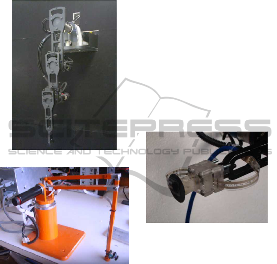
Figure 3: Planar robot manipulator.
Figure 4: Parallel robot manipulator.
5.2 Force Sensor
Most of commercial force sensors are expensive and
have large dimensions, which limit their applications.
On the other hand, low cost force sensors have re-
ceived attention from robotics community because
they are tiny and their applications are wider as ex-
plained in (Lebosse et al., 2008). In this paper
the low cost one axis force sensor from Tekskan
c
Flexiforce
c
is considered. The Flexiforce
c
A201
force sensor is made of two layers of polyester film.
On each layer, a conductive material (silver) is ap-
plied. Between the two layers a layer of pressure-
sensitive ink is applied. The active sensing area is
defined by the silver circle on top of the pressure-
sensitive ink. The force sensors are terminated with
male square pins, allowing them to be easily incorpo-
rated into a circuit. The force range of measurement
is 0− 100 N. The signal conditioning circuit for the
force sensor consists of an operational amplifier and
analog filter as proposed at the data sheet provided by
the fabricant.
5.3 Force Sensor Mounting
In order to ensure that the force is always applied on
the force sensing area, a mechanical cover was de-
signed and build. A finger-type silicon cover was
placed at the end-effector to consider a soft finger
contact type. The sensor was then mounted on the
end-effector of each robot manipulator, as shown in
Figure 5.
Figure 5: Force sensor mounting.
6 RESULTS
The goal is that the robots at the cooperative sys-
tem grasp and move a prismatic shaped object, which
is a high density Styrofoam block (6 × 6 × 5[cm],
mass = 0.03[Kg]). The block is affected by gravity
forces, as shown in Figure 6. The ideal desired po-
sition is such that perpendicular contact between the
object and the end effectors is obtained. This guar-
antees that the interaction forces are aligned to the
force sensor axis. Two cases are tested, external force
perturbation on a grasped object, and transporting a
grasped object by the cooperative system.
A grasping analysis was carried out to select the
best grasping positions on the object, while consider-
ing its inertial properties, (Murray and Sastry, 1994).
Therefore, the selected grasping points are located
at the centroid of the opposite squared faces of the
block, and assuming a static friction coefficient µ =
AN OPTIMAL ADMITTANCE REACTIVE FORCE CONTROL FOR COOPERATIVE ROBOT GRASPING TASKS
55
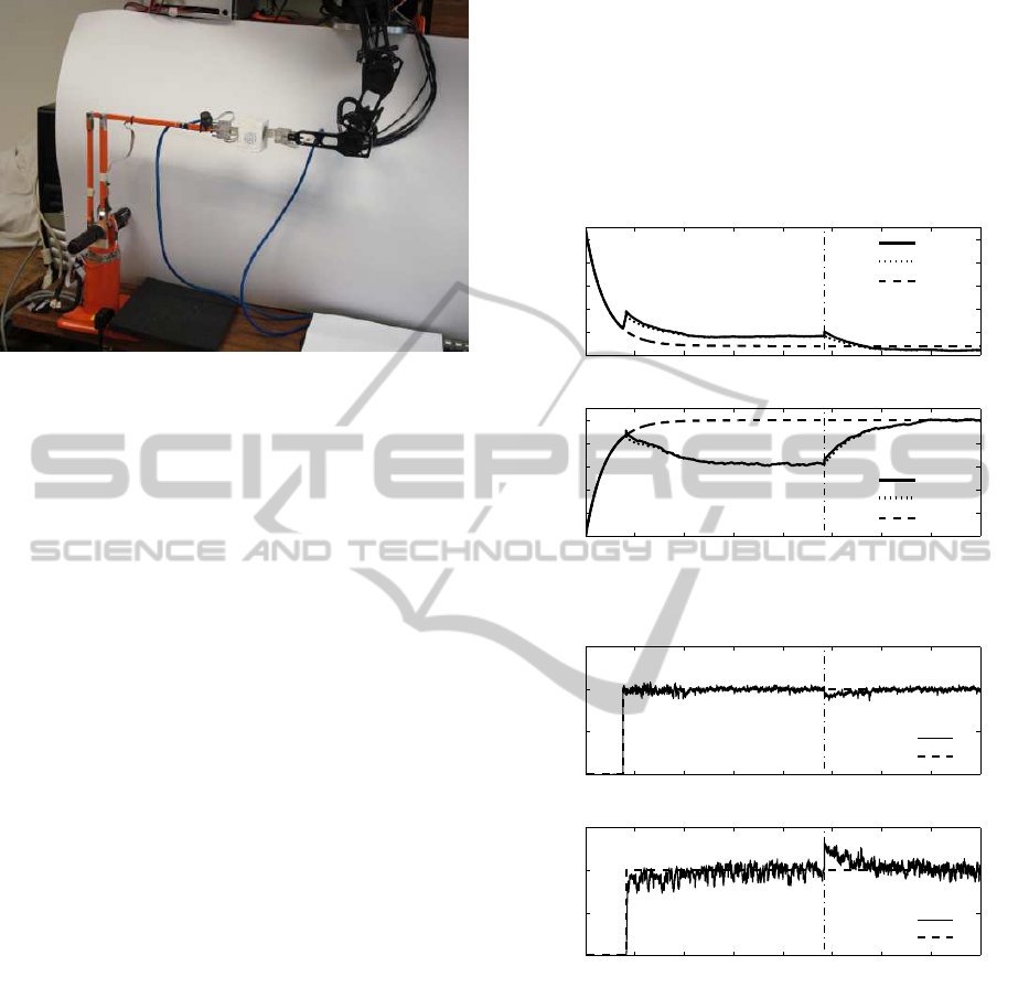
Figure 6: Cooperative grasping task.
0.5 (plastic-styrofoam), the desired force which guar-
antees stable grasp is F
r,i
= 0.265[N]. However, due
to uncertainty on the friction coefficient and the un-
known stiffness coefficient K
o,i
we set F
r,i
= 1[N].
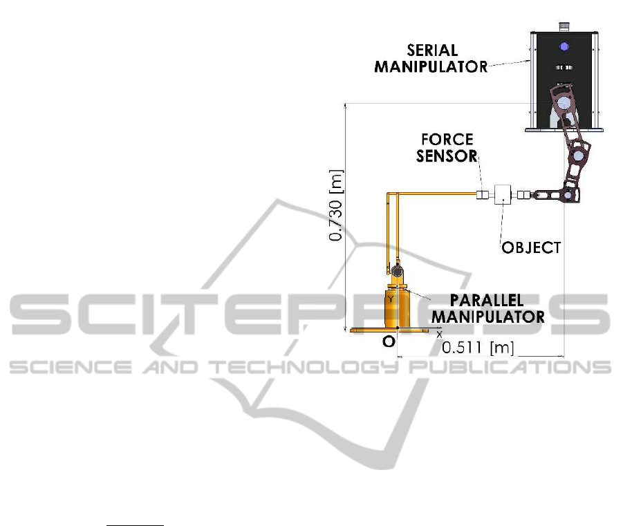
6.1 Experiment Setup
To perform cooperative transport, both manipulator
workspaces must intersect in the area where the object
is transported. This fact imposes some restrictions to
the experimental set-up. First, a reference frame must
be selected to provide an absolute value of the object
position, as shown in Figure 1. On the other hand, the
parallel manipulator is spatial and the serial manipu-
lator is planar. Then, we are limited to perform coop-
erative tasks in the 2D serial robot workspace. This
is accomplished by fixing the first degree of freedom
of the parallel manipulator that is in charge of waist
rotation. The final configuration for the experiments
is shown in Figure 6.
The experiments were performed as follows. First
the manipulators are commanded to a home position
with its end-effectors near the object, i.e. the object
position is not exactly known. Once the manipulators
are at home, they are commanded to pinch or squeeze
the object by two contact points applying the desired
force, previously selected via the grasp analysis. The
pinch command is performed by setting the end effec-
tor trajectories such that the difference between the
end effectors is smaller than the width of the block,
W = 0.05[m]. The gains of the admittance controller
were set to γ
1
= 0.00022 and α
1
= 0.1, for the parallel
robot and γ
2
= 0.001 and α
2
= 0.1 for the serial robot.
6.2 Test of Stable Grasp
At the first case a fixed object position is commanded,
and after the setting forces have reached the steady
state, the object is perturbed by an unknown external
force. The goal is that the controller compensates the
external force ensuring stable object grasp. The prob-
lem arises in the pinch command. Due to the uncer-
tainty on the object position, unexpected forces may
appear, which are not desirable for the grasp because
they can cause unstable behavior or contact break-
age/slippage.
0 5 10 15 20 25 30 35 40
0.352
0.353
0.354
0.355
0.356
0.357
Time [s]
X [m]
Cartesian trajectories of serial robot
X
X
c
=X
d
+X
r
X
d
0 5 10 15 20 25 30 35 40
0.3
0.301
0.302
0.303
0.304
0.305
Time [s]
X [m]
Cartesian trajectories of parallel robot
X
X
c
=X
d
+X
r
X
d
Figure 7: Cartesian trajectories.
0 5 10 15 20 25 30 35 40
0
0.5
1
1.5
Time [s]
F [N]
Force tracking of serial robot
F
F
d
0 5 10 15 20 25 30 35 40
0
0.5
1
1.5
Time [s]
F [N]
Force tracking of parallel robot
F
F
d
Figure 8: Force regulation.
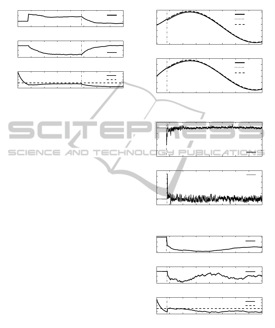
The desired X
d,i
, commanded X
c,i
and robot carte-
sian X
i
trajectories are shown in Figure 7. The dashed
line represents the desired trajectory X
d
, which is de-
signed to perform the pinch command and to grasp the
object. Thus, the optimal admittance controller gener-
ates proper trajectories in order to achieve the desired
force F
r,i
= 1[N], which are shown in Figure 8. Then,
around time t = 24[s], an external force is applied on
the object in the negative direction with respect to the
global reference frame O (see figure 1), this effect is
depicted in Figures 7 and 8.
Figure 9 shows the optimal reference trajectories
X
r
, generated to keep the stable grasp, despite the un-
ICINCO 2011 - 8th International Conference on Informatics in Control, Automation and Robotics
56
0 5 10 15 20 25 30 35 40
−5
0
5
10
x 10
−4
Time [s]
X
r
[m]
Optimal trajectory generation for the serial robot
X
r
0 5 10 15 20 25 30 35 40
−2
−1
0
1
x 10
−3
Time [s]
X
r
[m]
Optimal trajectory generation for the parallel robot
X
r
0 5 10 15 20 25 30 35 40
0.048
0.05
0.052
0.054
0.056
Time [s]
H [m]
Distance between manipulator‘s end effector (H), and object Width (W)
H
W
Figure 9: Optimal trajectories.
certainty in object position, friction coefficient, stiff-
ness and external perturbations. The bottom plot of
Figure 9 shows that the generated trajectories makes
the robot to grasp the object by squeezing it, thus
the distance between the end effectors, H is such that
H < W.
6.3 Object Position by Grasping
For the second experiment the robots are commanded
to follow a desired trajectory in cartesian space while
stable grasping is guaranteed.
The first step is to grasp the object stably, while
the manipulators are commanded to follow a syn-
chronized sinusoidal trajectory along the x axis of the
global coordinate frame, located at the base of the
parallel manipulator. The cartesian trajectories are
shown in Figure 10.
Before the object contact time t ≈ 4[s], the robots
follow their trajectories accurately, however after t ≈
4[s], the admittance controller modifies the com-
manded trajectories by generating reference trajecto-
ries X
r
, which yields the force set point, the force
tracking errors are shown in Figure 11. Again, the
bottom plot of Figure 12 shows that the generated
trajectories makes the robot to grasp the object by
squeezing it, thus the distance between the end effec-
tors, H is such that H < W.
7 CONCLUSIONS AND FUTURE
WORK
In this paper an optimal reactive admittance approach
for safe robot-object interactions in cooperative robot
grasping task is proposed. The optimal admittance
controller is free of robot dynamic model, however it
0 5 10 15 20 25 30 35 40
0.3
0.32
0.34
0.36
0.38
0.4
Time [s]
X [m]
Cartesian trajectories of serial robot
X
X
c
=X
d
+X
r
X
d
0 5 10 15 20 25 30 35 40
0.26
0.28
0.3
0.32
0.34
0.36
Time [s]
X [m]
Cartesian trajectories of parallel robot
X
X
c
=X
d
+X
r
X
d
Figure 10: Cartesian trajectories.
0 5 10 15 20 25 30 35 40
−1
−0.8
−0.6
−0.4
−0.2
0
0.2
Time [s]
E [N]
Force tracking of serial robot
E
0 5 10 15 20 25 30 35 40
−0.2
0
0.2
0.4
0.6
0.8
Time [s]
E [N]
Force tracking of parallel robot
E
Figure 11: Force tracking errors.
0 5 10 15 20 25 30 35 40
−15
−10
−5
0
x 10
−4
Time [s]
X
r
[m]
Optimal trajectory generation for the serial robot
X
r
0 5 10 15 20 25 30 35 40
−2
−1
0
1
x 10
−3
Time [s]
X
r
[m]
Optimal trajectory generation for the parallel robot
X
r
0 5 10 15 20 25 30 35 40
0.048
0.05
0.052
0.054
0.056
Time [s]
H [m]
Distance between manipulator‘s end effector (H), and object Width (W)
H
W
Figure 12: Optimal trajectories.
has been shown by experimental results that our ap-
proach is effective, yielding stable object grasp. This
is achieved due to the fast on-line generation of the
reference trajectory, which modifies the commanded
trajectory to the motion controller. It is important
AN OPTIMAL ADMITTANCE REACTIVE FORCE CONTROL FOR COOPERATIVE ROBOT GRASPING TASKS
57

to highlight that the success of the implementation
of the admittance controller is dependent on the per-
formance of the motion controller. As future appli-
cations, this approach might be extended to consider
on-line repositioning of the contact points to increase
flexibility and robustness of cooperative robot sys-
tems.
ACKNOWLEDGEMENTS
All authors acknowledgesupport from CONACyT via
projects 133527and 084060. Second author acknowl-
edges support of CONACyT Mexico via scholarship
205757.
REFERENCES
Brock, O. and Khatib, O. (2002). Elastic strips: a
framework for motion generation in human environ-
ments. The International Journal of Robotics Re-
search, 21(12):1031–1052.
Chiaverini, S. and Sciavicco, L. (1993). The parallel ap-
proach to force/position control of robotic manipula-
tors. IEEE Transactions on Robotics and Automation,
9(4):361–373.
Chiaverini, S., Siciliano, B., and Villani, L. (1999). A sur-
vey of robot interaction control schemes with experi-
mental comparison. IEEE Transaction on Mechatron-
ics, 4(3):273–285.
Colbaugh, R. and Glass, K. (1997). Adaptive compliant mo-
tion control of manipulators without velocity mea-
surements. Journal of Robotic Systems, 14(7):513–
527.
Cortes-Martinez, R. (2007). Diseo y construccion de un
sistema de teleoperacion maestro esclavo no similar.
Master Thesis (In Spanish), Center for Research and
Advanced Studies (CINVESTAV-IPN), Mexico.
Duchaine, V. and Gosselin, C. (2009). Safe, stable and intu-
itive control for physical human-robot interaction. In
2009 IEEE International Conference on Robotics and
Automation, pages 3383–3388.
Helmke, U. and Moore, J. (1996). Optimization and Dy-
namical Systems. Springer-Verlag, London.
Hsiao, K., Chitta, S., Ciocarlie, M., and Jones, E. G. (2010).
Contact-reactive grasping of objects with partial shape
information. In IEEE/RSJ International Conference
on Intelligent Robots and Systems, pages 1228–1235.
Jung, S., Hsia, T. C., and Bonitz, R. G. (2001). Force track-
ing impedance control for robot manipulators with an
unknown environment: Theory, simulation and ex-
periment. The International Journal of Robotics Re-
search, 20(9):765–774.
Khatib, O. (1986). Real-time obstacle avoidance for robot
manipulators and mobile robots. The International
Journal of Robotics Research, 5(1):90–98.
Lebosse, C., Bayle, B., de Mathelin, M., and Renaud, P.
(2008). Nonlinear modeling of low cost force sensors.
In IEEE International Conference on Robotics & Au-
tomation, pages 3437–4342.
Muro-Maldonado, D. (2006). Control ptimo de Manip-
uladores Redundantes. Master Thesis (In Span-
ish), Center for Research and Advanced Studies
(CINVESTAV-IPN), Mexico.
Murray, R. M., L. Z. and Sastry, S. (1994). A Mathemati-
cal Introduction to Robotic Manipulation. CRC Press,
United Kingdom, 1st edition.
Pratt, J. and Pratt, G. (1998). Intuitive control of a planar
bipedal walking robot. In 1998 IEEE International
Conference on Robotics and Automation, pages 2014–
2021.
Roa, M. and Suarez, R. (2009). Computation of indepen-
dent contact regions for grasping 3D objects. IEEE
Transactions on Robotics and Automation, 25(4):839–
850.
Santis, A. D., Pierro, P., and Siciliano, B. (2006). The vir-
tual end-effectors approach for human-robot interac-
tion. In 10th International Symposium on Advances in
Robot Kinematics, pages 133–144.
Santis, A. D., Siciliano, B., Luca, A. D., and Bicchi, A.
(2008). An atlas of physical human-robot interaction.
Mechanism and Machine Theory, 43:253–270.
Sanz, P. J., Recatala, G., Traver, V. J., and del Pobil, A. P.
(1999). Towards a reactive grasping system for an in-
dustrial robot arm. In Computational Intelligence in
Robotics and Automation, CIRA 99, pages 1–6.
Schutter, J. D., Bruyninckx, H., Zhu, W., and Spong, M. W.
(1998). Force Control: a bird’s eye view. Lecture
Notes in Control and Information Sciences - Control
Problems in Robotics and Automation, Vol. 230.
Seraji, H. (1998). Nonlinear and adaptive control of force
and compliance in manipulators. The International
Journal of Robotics Research, 17(5):467–484.
Seraji, H. and Colbaugh, R. (1997). Force tracking in
impedance control. The International Journal of
Robotics Research, 16(1):97–117.
Shapiro, A., Rimon, E., and Shoval, S. (2010). On the
passive force closure set of planar grasps and fix-
tures. The International Journal of Robotics Research,
29(11):1435–1454.
Siciliano, B. and Khatib, O. (2008). Springer Handbook of
Robotics - Motion Control. Springer, London.
Simonin, O. (2006). Reactive multi-agent approaches for
the control of autonomous mobile robots. In 1st Na-
tional Workshop on Control Architecture of Robots:
software approaches and issues CAR 06, pages 183–
191.
Teichmann, M. and Mishra, B. (2000). Reactive robotics I:
reactive grasping with a modified gripper and multi-
fingered hands. The International Journal of Robotics
Research, 19(7):697–708.
Vahrenkamp, N., Wieland, S., Azad, P., Gonzalez, D., As-
four, T., and Dillmann, R. (2008). Visual servo-
ing for humanoid grasping and manipulation tasks.
In 8th IEEE-RAS International Conference on Hu-
manoid Robots, pages 406–412.
Yigit, S., Burghart, C., and Woern, H. (2003). Con-
cept of combined control mechanisms for human
robot co-operation. In International Conference on
Computer, Communication and Control Technologies
(CCCT ’03).
ICINCO 2011 - 8th International Conference on Informatics in Control, Automation and Robotics
58
