
COMPARING DETERMINIST AND PROBABILISTIC METHODS
FOR RFID-BASED SELF-LOCALIZATION AND MAPPING
Younes Raoui
1,2,3
, Michel Devy
2,3
, El Houssine Bouyakhf
1
and Fakhita Regragui
1
1
Faculty of Sciences, University Mohamed, V-Agdal Rabat, Morocco
2
CNRS, LAAS, 7 avenue du colonel Roche, F-31077 Toulouse Cedex 4, France
3
Universit´e de Toulouse, UPS, INSA, INP, ISAE, UT1, UTM, LAAS, F-31077 Toulouse Cedex 4, France
Keywords:
Mobile robot, Mapping, Extended Kalman filter, Particle filter, Monte-Carlo Localization, RFID.
Abstract:
This article deals with Simultaneous Localization and Mapping for an indoor robot equipped with a camera and
RFID antennas. RFID tags are sparsely disseminated in the environment. First RFID-based self-localization
is considered; the robot position is predicted from odometry; it is corrected first by a sequential Monte-Carlo
localization based on a particle filter. An active strategy built on the theoretical basis of information entropy is
applied in order to improve the position accuracy. Then two methods for RFID-based mapping are described,
considering the robot pose is given from natural visual landmarks learnt by a classical visual SLAM function.
1 INTRODUCTION
Roboticists must make more efficient and safe the
navigation of a robot in complex and dynamic envi-
ronment like shopping centers or airports. This work
concerns the design, implementation and evaluation
of a trolley robot that must learn advanced behav-
iors so as to assist a user when doing shopping in
a commercial center. Missions are defined in terms
of trajectories that the robot will execute using robust
control behaviours. Trajectories and robot positions
are expressed with respect to metrical representations
of the store. At each time instant, the robot requires
to know its position (XYθ) coordinates so that it can
reach its objective with a high accuracy. In (Raoui
et al., 2009), two RFID-based methods are compared
to deal with a two-steps localization strategy, consid-
ering either tags merged on the ground (RFID barri-
ers) or disseminated on shelves.
This paper focuses first on the self-localization
from a known RFID map, and then on the construc-
tion of this map. Self-localization is first based on
RFID tags considered as landmarks. So we equip our
robot with RFID antennas and at the same time we
place RFID tags in the environment. Two approaches
are compared, either deterministic based on Kalman
filtering, or stochastic based on the Particle filtering.
The latter one is more realistic because it takes better
into account uncertainties. Then, we propose a techn-
ique to enhance the location information with data
of antennas which don’t have observations Secondly,
we use visual landmarks for localization. Besides, in
each part, we show the results of robot navigation on
a predefined map.
Then mapping is considered only for RFID tags;
it is assumed that vision-based SLAM is executed us-
ing classical methods in order to learn visual land-
marks (Davison et al., 2007). By applying the model
perception of the RFID antennas, we estimate the po-
sition of tags assuming that the robot is located from
visual SLAM. We propose two algorithms, determin-
istic and probabilistic, which construct a map with
RFID tags.
This paper is organized as follows. After dis-
cussing related works, we will present the metrical
method for self localization in section 3. Then we
describe stochastic localization with par- ticle filter.
In section 5, we describe how we can localize our
robot with visual landmarks using the Pinhol cam-
era model. Finally, we present a deterministic and
bayesian methods for mapping with RFID tags.
2 RELATED WORKS
Trajectory can be estimated by using low cost pas-
sive RFID tags and odometry in unknown environ-
ment. This is a prerequisite for mapping RFID with
211
Raoui Y., Devy M., Bouyakhf E. and Regragui F..
COMPARING DETERMINIST AND PROBABILISTIC METHODS FOR RFID-BASED SELF-LOCALIZATION AND MAPPING.
DOI: 10.5220/0003533802110216
In Proceedings of the 8th International Conference on Informatics in Control, Automation and Robotics (ICINCO-2011), pages 211-216
ISBN: 978-989-8425-75-1
Copyright
c
2011 SCITEPRESS (Science and Technology Publications, Lda.)
particle filters approach without any other position-
ning systems. This method avoids the noisy nature of
RFID measurements and the absence of distance and
bearing information as it is based on a non-parametric
model for spatial relationships between RFID mea-
surements. One of the first surveys of localizing a
mobile robot via RFID was developed by Hanel et
al. (Hahnel et al., 2005). They used a probabilistic
sensor model for their RFID reader, in order to ex-
press the probability of tag detection from the relative
position between the tag and the antenna. This model
is exploited to map the positions of passiveRFID tags,
considering that the robot has already learnt an envi-
ronment model from a laser based FastSLAM func-
tion (Montemerlo et al., 2002). Finally, given the
RFID-based map, the robot was finally able to local-
ize itself with only RFID and odometry; tags positions
are represented by a number of particles, and weights
are updated at each detection of the tag. Another set
of particles is used to represent the robot pose accord-
ing to the MonteCarlo localization.
Kleiner et al (Kleiner et al., 2007) have performed
trajectory correction and GraphSLAM with sparsely
spread passive transponders. Other works have ex-
ploited active RFID tags. For example, Kantor et
al (Kantor et al., 2003) used EKF for localization,
mapping and SLAM. They exploit measured signal
strength received from transponders in order to mea-
sure the robot-tag distance, but such a measurement
is not available for passive RFID systems. Yamano
et al (Yamano et al., 2004) examinate how Support
Machine Vector could learn robot localizations. This
is applied by generating feature vectors from the sig-
nal strength information acquired with active RFID
tags. Ziparo et al (Ziparo et al., 2007) used RFIDs
to coordinate a team of robots for an exploration in
unstructured areas.
Several authors combine vision and RFID based
sensing. Chae et al (Chae and Han., 2005) computed a
weighted sum of the currently detected tags positions;
then the robot was localized at a finer scale by monoc-
ular vision involving SIFT features. Tsukiyama et
al (Tsukiyama., 2003) developped a simple naviga-
tion mechanism on the basis of vision for free space
detection. RFID tags were considered as labels for
the topologicalrobot localization. Recently Zhou et al
((Zhou et al., 2007)) proposed a vision based indoor
localization method based on modified active RFID
tags; tags were equipped with LEDs which make the
recognition much easier.
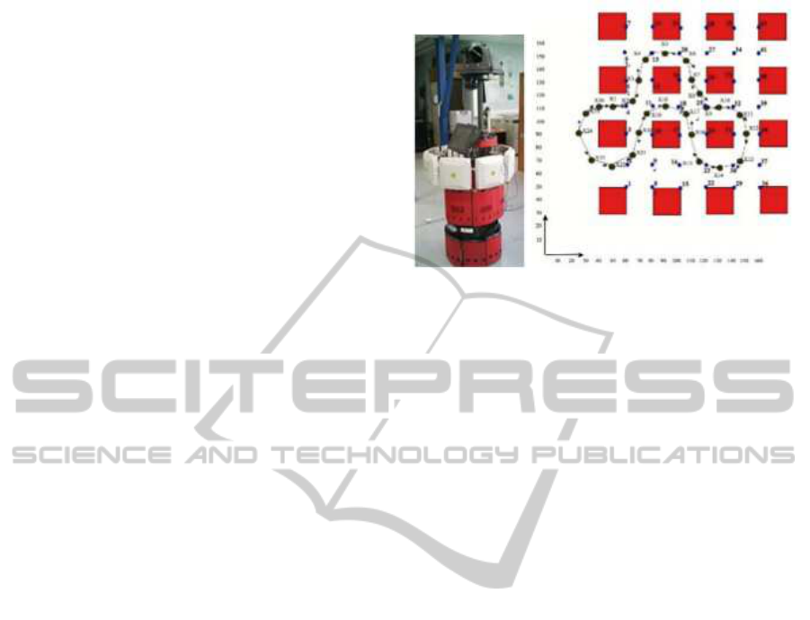
Figure 1: The RACKHAM demonstrator (left); a simulated
trajectory (right).
3 METRICAL AND
DETERMINISTIC METHOD
FOR SELF-LOCALIZATION
We propose an approach for topological navigation
based on sparsely distributed RFID tags. The op-
erator sets RFID tags (with known labels) in dedi-
cated places so that when the robot receives the signal
from one tag, it knows that this tag is in the recep-
tion field of the antenna. The Rackham demonstra-
tor (figure 1(left)) is equipped with 8 directional an-
tennas. Figure 1(right) presents a simulated environ-
ment, with a simulated trajectory the robot has to ex-
ecute: the blue dots numbered from 1 to 42 are RFID
tags the positions of which are assumed to be known
at this step. The robot starts from the position X
1
; its
position after a motion between two successive posi-
tions X
i
and X
i+1
is predicted from odometry.
The robot model is known so that the odometer
delivers motion measurements (u;Q) In the current
robot reference frame , with u = (dx;dy;dθ) and Q
the covariance matrix on u. Figure 2 shows the pre-
dicted robot position X
i
for the simulated trajectory,
executed without observation. The odometry errors
are cumulative, so that at the end, the robot position
prediction has a high uncertainty. This uncertainty
can be maintained constant when observing RFID
tags, using a stochastic framework that allows to
fuse measurements acquired by odometry (in order
to predict the robot position from the estimated
motions) with other information coming from RFID
observations.
Taking into Account Only Observations. Fig-
ure 3 describes the different steps of our determin-
istic method. We analyze these steps between the
ICINCO 2011 - 8th International Conference on Informatics in Control, Automation and Robotics
212
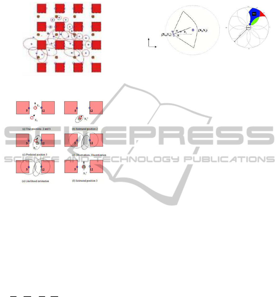
Figure 2: Predicted positions from the robot model (odom-
etry, EKF update of the last estimated position).
Figure 3: Mixed approach: EKF used to fuse odometry
measurements, MLE used to evaluate consistent hypothe-
sis with the RFID observations.
two positions 2 and 3: the true positions are pre-
sented in (a). Two tags labelled 5 and 12 will be
detected when arriving at position 3. In (b) the es-
timated X
e
2
position is presented with the elliptic un-
certainty area in which the true robot position must
be with a probability 0.95: this ellipse is computed
from the covariance matrix P
e
2
on the position vector
(X;Y;θ). In (c), the robot moved from X
2
to X
3
, and
predicts its new position from the odometry measure-
ments u, thanks to a function F: X
∗
3
= F(X
e
2
, u) The
error P
∗
3
on X
∗
3
is computed using a linearization of F:
P
∗
3
=
dF
dX
P
e
2
dF
t
dX
+
dF
du
Q
dF
t
du
In (d) the robot receives RFID signals. If the robot
is only equipped with one omnidirectional antenna,
when it receives the signal from an RFID located in
a position (X
t
;Y
t
) , we can apply a constraint on its
position (X
r
;Y
r
):
(X
t
+ X
r
)
2
+ (Y
t
+Y
r
)
2
< R
2
where R is the maximal distance between the tag
and the antenna. So without considering the orien-
tation, when the robot receives in X
3
, the RFID sig-
nals from tags 5 and 12, it means that its true position
is located inside the two discs drawn in (d). Using
the classical EKF-based framework for robot local-
ization, it is not possible to express such a constraint.
Figure 4: Reception field of one antenna (left). Reception
field of eight antennas mounted on a circular robot (right).
Hypothesis on the robot position are randomly sam-
pled from the gaussian distribution (X
∗
3
, P
∗
3
) : then the
likelihood of each particle is estimated with respect
to the observation constraints. In (e) only the parti-
cles in the two discs intersection are kept, and finally
in (f), the estimated position X
e
3
is computed using the
barycenter of the acceptable particles, and the uncer-
tainty P
e
3
is evaluated from the eigen vectors and eigen
values of the cloud of the acceptable particles.
Using only an omnidirectional antenna, it is not
possible to update the robot orientation. But if the
robot is equipped with several directional antennas,
other constraints can be applied on the robot position
and orientation from the observation of one RFID tag
from one known antenna. Figure 4 presents the cali-
brated reception fields: antennas receive signals emit-
ted in a 120 deg cone, from less than 4,5 meters. A
tag can be received from one, two or three antennas,
depending on its position with respect to the robot in
the red, blue and green regions. When a tag located
in (X
t
;Y
t
) is received by an antenna located in (X
a
;Y
a
)
with an orientation θ
a
with respect to the world frame
(see figure 4(right)), it gives two new constraints : the
tag must be in the reception field, i.e. in the disk, but
also between two straight lines.
Similar constraints can be applied also if a tag
is not received. So these constraints are applied in
order to estimate the likelihood of a robot position
estimate from observations of tags with our RFID
reader connected to eight antennas. Figure 5 shows
the estimated robot positions and orientations X
e
i
with the simulated environment and trajectory.
Filtering Non-observations. The method presented
in the previous section, doesn’t use the information
about antennas of the robot which does not have ob-
servations. These information can be integrated to
have more precision in the localization. In order to
increase such accuracy, we apply the following algo-
rithm on each step of the robot path:
• Computing the robot observation in the current
step based on the model of the antennas.
• Finding the particles around each predicted posi-
COMPARING DETERMINIST AND PROBABILISTIC METHODS FOR RFID-BASED SELF-LOCALIZATION AND
MAPPING
213
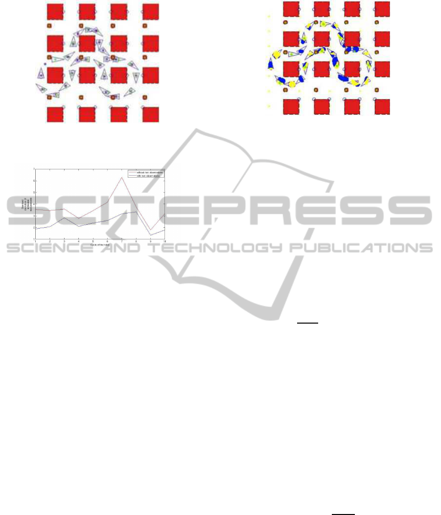
Figure 5: Robot localization at different positions with the
computation of standard deviation for x, y, θ.
Figure 6: True error on ¡X coordinate for 10 robot cycles,
considering non observations.
tion with a covariance of P
y
computed in the Kalman
update step, that receive the same RFID tags as the
observation.
• Considering only the particles that receive the
same tags as observation.
• Rejecting particles that receive other tags.
We do statistical measures in order to show how
the performances of localization are improved with
the non observation operation. For that, we move
the robot with different error noises. At each cycle,
we compute the standard deviation of measurements
( xEst-xTrue) for the case of using non observations
or not using non observations. The results are pre-
sented in figure 6: errors are decreased when taking
into account non observations. Figure 7 shows the
distribution of particles on the robot poses.
4 STOCHASTIC LOCALIZATION
USING PARTICLE FILTER
The method is based on the particle filter and includes
some modifications that improve the localization per-
formance. We consider then the approach based on
the modeling of physical properties of the sensor and
the observation process. We explain the principal
steps of the algorithm and the improvement that we
Figure 7: Evolution of the distribution of particles ( by con-
sideration of non observations, we keep only yellow parti-
cles).
do. First, we initialize the algorithm with a uniform
distribution of the positions of our environment if we
don’t know the first position of the robot; or with a
distribution centred on the first position if we know
it. Then at each iteration, we apply the following
steps((Vorst et al., 2008)) :
• Prediction of the movement :in this step we use
the displacement estimated by the odometer and
the displacement model for taking the next posi-
tion in the probability distribution of the next po-
sitions. We modify this behavior by taking N
t
po-
sitions instead of 1 position. We obtain the set
M
k
and we associate for each particle Mk[i] the
probability of
F
k−1
[i]
N
t
. We obtain then N
t
.N
sample
particles.
• Insertion of random particles : We insert N
aux
particles uniformly distributed in the environment
with an association of a low probability p
aux
. This
step allows a quicker correction if the robot is lost
which influences all the generated particles
• Integration of the observations: We change the
probabilities of N
t
.N
sample
+ N
aux
points with the
measure of the correspondences with observa-
tions.
• The resampling step This step takes in entry the
precedent points with their new probabilities and
generates the final set with taking uniformly N
sample particles among them. The probabilities
associated to these new particles will be equal
each other and equal to
1
N
sample
.
We present below the results of the simulation in
which 300 samples are used, with the probability dis-
tribution of the odometer set to be 3, the number of
injected particles set to be 30. Figure 8, presents the
aggregation of the first 20 displacements.
ICINCO 2011 - 8th International Conference on Informatics in Control, Automation and Robotics
214
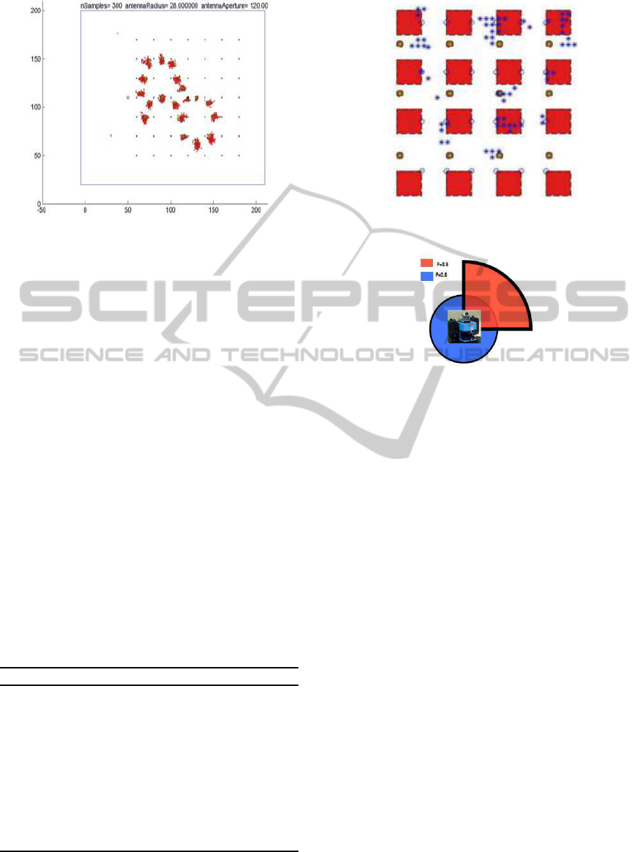
Figure 8: Stochastic simulation, the particles are illustrated
with red points.
5 MAPPING WITH RFID TAGS
RFID-based mapping is processed separately from lo-
calization, which means that we perform first local-
ization, obtain the positions of our demonstrator, then
we do mapping. Because the RFID-based map is ini-
tially unknown, another localization method must be
integrated in the robot; it is the reason why a visual
SLAM function is integrated on the robot. Consid-
ering the robot pose is known, two methods are pro-
posed in order to build the RFID map.
5.1 Deterministic Method
The robot circulates in the environment. At each time
it detects a new tag, it reduces its areas of mapping.
Supposing it is firstly in the area A, it draws a zone of
existence that corresponds to the model of perception
of the antennas; after advancing, the new zone is the
intersection of the two zones, and so on. We follow
these steps until we don’t receive any more tag. The
algorithm 1 describes this method.
Algorithm 1
1: for tag ← 1 to N do
2: for robot-position ← 1 to P do
3: detected-tags = scan(environment)
4: if detected-tags 6=
/
0 then
5: memorize this zone z
robot−position
6: intersect with the precedent
z
robot−position−1
7: end if
8: end for
9: end for
Figure 9: Estimated positions of the tags with blue stars
(First algorithm).
Figure 10: Simplified sensor model for one robot antenna.
5.2 Probabilistic Method
While the robot moves, it verifies whether it receives
some tags. If not, it continues until it receives a
tag. It discretizes the zone according to the percep-
tion model and then, for each particle it verifies if
it is received from the past zones. If not, it is dis-
carded. We need to know the posterior p(x|z
1:t
) ) for
each particle. x is the predicted pose of the tag and
z1:t represents the data gathered in the time step 1:t.
We use the Bayes rule which considers the assump-
tion of independence of consecutive given measure-
ments. We obtain the following recursive update rule
: p(x|z
1:t
) = α.p(z
t
|x)p(x|z
1:t−1
), where p(z
t
|x) spec-
ifies the likelihood of the observationz
t
given the pose
x of the tag relative to the robot pose. Algorithm 2 de-
scribes the different steps of the method.
For this mapping process, a simplified antenna
model is made of 2 components. Figure 10 shows
the detection range for each antenna. It consists of
an arc with an opening angle of 95 degrees in the di-
rection of the antenna. Besides, RFID tags which are
close are always detected. This is modeled by a circle
around the center of the receiver. The corresponding
likelihood is depicted for two detection ranges.
We apply this method by considering the poste-
rior positions which do not receive any tag that allows
to filter more particles. We evaluate our method by
computing both for x and y coordinates of the tag, the
COMPARING DETERMINIST AND PROBABILISTIC METHODS FOR RFID-BASED SELF-LOCALIZATION AND
MAPPING
215
Algorithm 2
1: for tag ← 1 to N do
2: for robot-position ← 1 to P do
3: repeat
4: R=Memorize the robot position
5: until received-tags 6=
/
0
6: P ← ellipse(robot-position)
7: for x
i
← 1 to size(P) do
8: p(x
i
|z
1:t
) = α.p(z
t
|x
i
)p(x
i
|z
1:t−1
)
9: if R
i
receives p
i
then
10: reject p
i
11: end if
12: end for
13: end for
14: end for
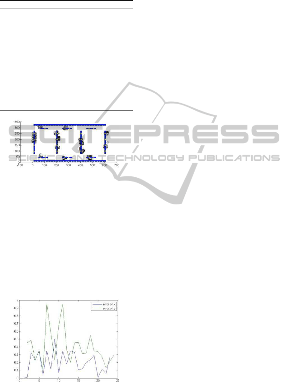
Figure 11: Estimated positions of the RFID tags. The color
of the circles represent the posterior probability of the cor-
responding positions.
difference between the average of the predicted po-
sitions, and its true position. We show in figure 12
the error on x coordinate (blue), and on y coordinate
(green). The accuracy is found to be about 0.2 m on x
axis, and 0.4 m on y axis.
6 CONCLUSIONS
This paper is focused on two approaches for RFID-
based self localization and mapping, using determin-
istic and probabilistic methods. These methods use
Figure 12: Error positionning of the tags.
respectively Kalman and Particle filters. First the
Monte Carlo localization has been implemented for
self localization. To improve the performances, we
have discarded the predicted positions that receive
tags not belonging to the observation. Secondly, for
the mapping, our sensor model allows us to compute
the likelihood of tag detection given the robot pose,
computed by a visual SLAM approach.
REFERENCES
Chae, H. and Han., K. (2005). Combination of rfid and
vision for mobile robot localization. Proc. Intelligent
Sensors, Sensor Networks and Information Processing
Conf.
Davison, A., Reid, I., Molton, N., and Stasse, O. (2007).
Monoslam: Real-time single camera slam. IEEE
Trans. on PAMI, Vol. 29, No. 6.
Hahnel, D., Burgard, W., Fox, D., Fishkin, K., and Filipose,
M. (2005). . mapping and localization with rfid tech-
nology. Proc. ICRA.
Kantor, G., Singh, S., Peterson, R., Rus, D., Das, A., Ku-
mar, V., Pereira, G., and Spletzer, J. (2003). Dis-
tributed search and rescue with robot and sensor team.
Proc. FSR.
Kleiner, A., C.Dornhege, and S.Dali (2007). Mapping dis-
aster areas jointly: Rfid-coordinated slam by humans
and robots. Proc. SSRR.
Montemerlo, M., Thrun, S., Koller, D., and Wegbreit, B.
(2002). Fastslam: A factored solution to the simulta-
neous localization and mapping problem. Proc. AAAI.
Raoui, Y., Goller, M., Devy, M., Kerscher, T., Zollner, J.,
Dillmann, R., and Coustou, A. (2009). Rfid-based
topological and metrical self-localization in a struc-
tured environment. In Proc. ICAR.
Tsukiyama., T. (2003). Navigation system for mobile robots
using rfid tags. Proc. ICAR.
Vorst, P., Schneegans, S., Yang, B., and Zell., A. (2008).
Self-localization with rfid snapshots in densely tagged
environments. Proc. IROS.
Yamano, K., Tanaka, K., Hirayama, M., Kondo, E., Kimuro,
Y., and Matsumoto, M. (2004). Self-localization of
mobile robots with rfid system by using support vector
machine. Proc. IROS.
Zhou, Y., Lu, W., and Huang, P. (2007). Laser-
activated rfid-based indoor localization system for
mobile robots. Proc. ECMR.
Ziparo, V., Kleiner, A., Farinelli, A., and Marchetti, L.
(2007). Cooperative exploration for usar robots with
indirect communication. Proc. IAV.
ICINCO 2011 - 8th International Conference on Informatics in Control, Automation and Robotics
216
