HUMANOID ROBOT
Modular-Joint Design of a TPINOKIO Bipedal Robot
Teck-Chew Wee, A. Astolfi
Department of EEE, Contol & Power Group, Imperial College London, London, U.K.
Ming-Xie
Department of MAE, Nanyang Technological University, Nanyang Avenue, Singapore
Keywords: Humanoid, Bipedal Robot, Modular-Joint design.
Abstract: This paper presents the work done in the modular-joint design of a teen-size bipedal humanoid robot. Due to
this modular-joint design approach, the robot is able to be modelled as a point-mass system without
considering its links’ inertia, this is a novelty approach to improve the kinematics and dynamic modelling of
the robot, for test-bedding and simulation of various control algorithms. The robot is a cost effective
platform which is suitable for both edutainment and engineering research purposes. The TPinokio humanoid
robot has a height of around 1.5 meter, and weight around 58 kg. This paper is focused mainly on the
robot’s mechanical structure and electronics design. The robot’s kinematics with point-mass distribution
characteristics and it’s control approach are briefly discussed.
1 INTRODUCTION
The development of bipedal robot locomotion began
more than 30 years ago, some well-known robots are
ASIMO, HRP, HUBO, JOHNNIE, LOCH and
QRIO. The success of ASIMO triggered a
worldwide research fever on humanoid robot.
Currently, most of the researchers faced numerous
challenges including difficulties in designing a low
cost; the fact that a life-size humanoid robots are
complex and expensive in cost; and yet robust in
mechanical structure robot. The other difficulties are
in obtaining a precision sensors feedback reading
and difficulties in implementing a high end real-time
motion controller.
Stable walking gait pattern generation and real-
time on-line control algorithm design remain a very
challenging tasks in the humanoid robotics research
arena, because it requires precision modelling of the
robot’s dynamics and kinematics, this include the
mass distribution, the location of Center-of-Mass
(CoM) and the inertia of each links. Therefore, to
obtain a correct and accurate robot’s model is
crucial. With this in mind, the mechanical structure
of TPinokio is in modular-joint form, all the critical
masses are concentrated at the joints end, and the
links between each joints are made of light-weight
aluminum, as such, the moment and inertia of the
links are negligible compared to the joints’ mass.
This results in a more accurate multi-body point-
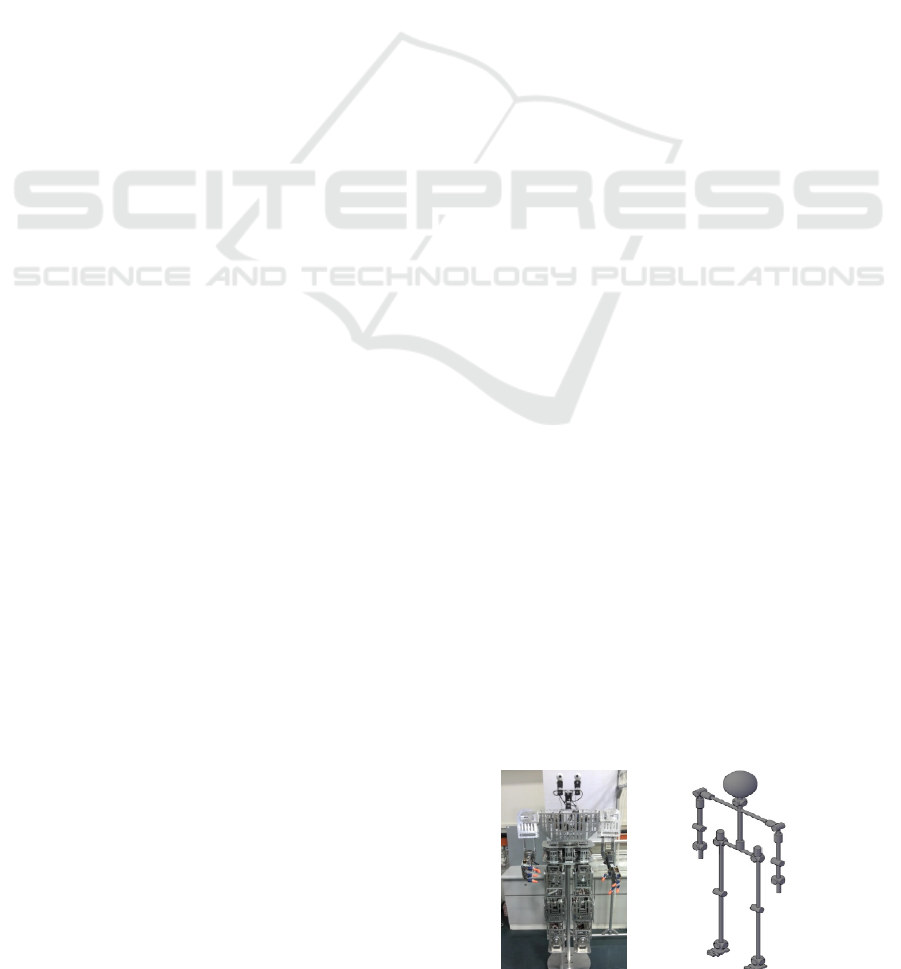
mass system model. TPinokio platform is designed
to be suitable for educational learning and
engineering research. The design is depicted in
Figure (1).
2 TPINKIO DESIGN CONCEPT
This section will outline the design concept of
TPinokio, the design concept are relatively low cost,
modular-joint and light weight.
Figure 1: TPinokio modular-joint design and point-mass
distribution stick diagram.
185
Wee T., Astolfi A. and . M..
HUMANOID ROBOT - Modular-Joint Design of a TPINOKIO Bipedal Robot.
DOI: 10.5220/0003530301850190
In Proceedings of the 8th International Conference on Informatics in Control, Automation and Robotics (ICINCO-2011), pages 185-190
ISBN: 978-989-8425-75-1
Copyright
c
2011 SCITEPRESS (Science and Technology Publications, Lda.)
2.1 Special Features
Compact and modular-joint design.
Can be easily modelled as ‘point-mass’.
Robust mechanical structure.
Simple kinematics.
Zero backlash.
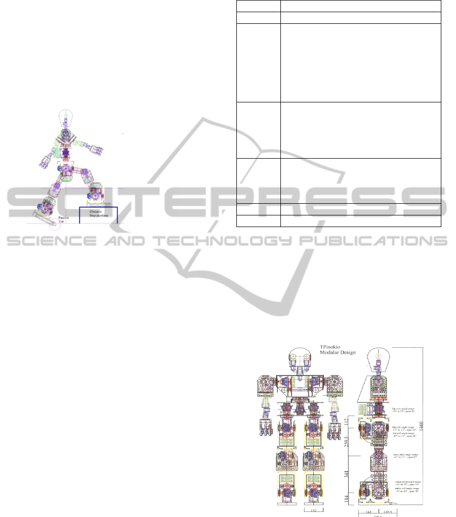
Passive toe-joint to achieve better walking
speed and higher step climbing, as shown
in Figure (2).
Figure 2: Passive toe joint for higher step climbing.
2.2.1 Comparatively Low Cost
All the components were carefully evaluated before
a purchase was made, the total fabrication cost is
below US$50k.
2.2.2 TPinokio for Research
The robust, light-weight, modular-joint and
relatively low cost design of TPinokio provides an
affordable test-bedding platform for researchers.
2.2.3 TPinokio for Education
Due to its light-weight and easy software interface
(Labview), a wide range of low cost sensors and
electronics gadgets may be added to the upper body
of the robot. It is a good edutainment platform to
cultivate learning interest in robotics.
2.2 Degree of Freedom (D.O.F)
TPinokio has more than 40 D.O.F, it is around 1.5m
and weight approximately 56kg. The general
specifications are listed in Table (1).
Table 1: TPinokio Specifications
Height Approx. 1.5meter
Weight Approx. 56 kg
DOF Lower body : 12 DOF
Waist ( Pelvis) : 1 DOF
Upper body ( Shoulder, Arm): 12 DOF
Hands : 16 DOF
Head ( neck ) : 2 DOF
Eyes : 4 DOF
Total : 47 DOF
Actuator Lower body: Harmonic gear, DC motor
Upper body (shoulder) : Harmonic gear, DC
motor
Arm: EX106, RX64, RX28. RX10
Hand : low cost RC servo motor
Sensors Head : USB Webcam, Hokuyo LRF
Pelvis : IMU
Foot : FSR
Joint : Tilt sensor & absolute encoder
Power 24V DC
Software LabVIEW 2010
3 OVERVIEW OF DESIGN
3.1 Mechanical Design
The CAD drawing of the TPinokio design is as
depicted in Figure (3), a trade-off between cost
effectiveness and performance requirements.
Figure 3: TPinokio CAD drawing.
3.1.1 Modular-joint Design
In total, there are three set of different modular-joint
design, namely, hip joint, knee joint and ankle joint
respectively. The joint-shaft is driven by a DC motor
coupled with a harmonic drive through a pulley-belt
ICINCO 2011 - 8th International Conference on Informatics in Control, Automation and Robotics
186
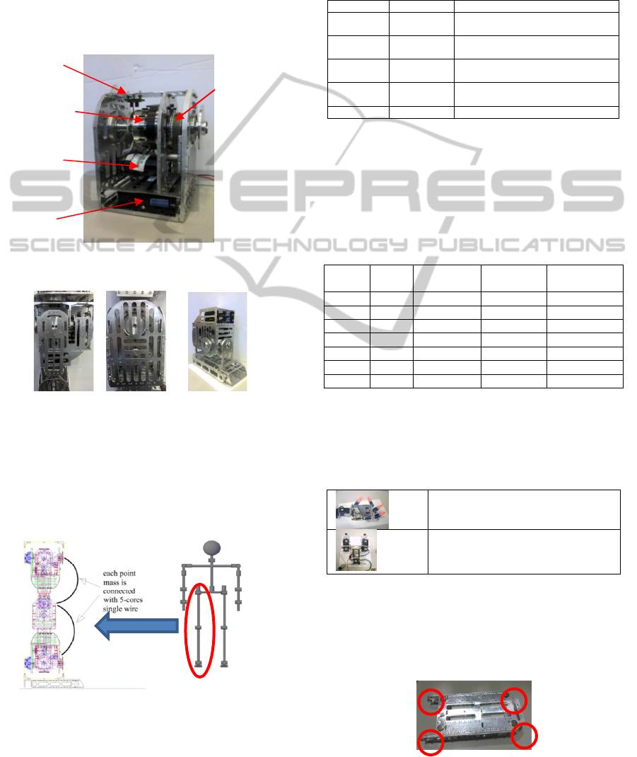
system. All the sensors, controller electronics and
wiring harness are housed in a compact housing, as
shown in Figure (4) and Figure (5). Most of the
components are standardised with 85% similarity in
specifications, only the motors and Harmonic-gears
have different specification due to its different
torques requirement for each joints. As such, the
modular-joint can be easily swap, reconfigure, or
removal for repair and maintenance.
Figure 4: Compact Modular-Joint Design.
Hip Joint Knee Joint Ankle Joint
Figure 5: Different set of compact modular-joint.
Communication between each modular-joint is
through CANbus interface with a single five-core
cable; 3-wires for the CANbus and 2-wires for the
power supply; thus, messy cabling is eliminated, as
depicted in Figure (6).
Figure 6: CANbus link between Modular-Joint.
3.1.2 Upper Body Design
The upper body joints are designed with low cost
components, the essential parts are listed in Table
(2).
Table 2: Upper Body actuators.
Joint Actuator
Head Pitch yaw
RX10
RX10
Shoulder Pitch yaw
Harmonic 14-100:1 and Maxon 90w
DC motor
Arm Pitch yaw
EX-106+
EX-106+
Hand /
Wrist
Pan/Tilt
Roll
RX64
RX28
Fingers Pan/Tilt RC servo
3.1.3 Lower Body Design
These include the pelvis and both legs. The lower
body has a 13 D.O.F, the joints are modular, the
pulley-belt system is standard components for all
joints, as listed in Table (3).
Table 3: Lower body actuators.
Joint
Harmonic
gear
Pulley &
belt ratio
DC Motor
Pelvis yaw Size 17 2:1 150w
Hip Roll Size 17 2:1 150w
Pitch Size 20 2:1 150w
Yaw Size 20 2:1 150w
Knee Pitch Size 17 2:1 200w
Ankle Roll Size 14 2:1 150w
Pitch Size 20 2:1 150w
3.1.4 Arm, Hand and Head Design
The upper body parts are assembled with low cost
components and parts. It is designed mainly for
edutainment purposes.
The fingers are design with HiTec
HS-55 RC servo.
The eyes have two USB webcam ,
pan / tilt can be controlled by
Dynamixel RX10 servo.
3.2 Sensory System
Foot dynamics affect the overall walking
performance. TPinokio feet are designed with FSRs
mounted at four corners, as shown in Figure (7).
Figure 7: FSRs mounting at the base of the foot.
Pulley & Belt
System
Harmonic
gear
Motor
EPOS2
Encoder Sensor
HUMANOID ROBOT - Modular-Joint Design of a TPINOKIO Bipedal Robot
187
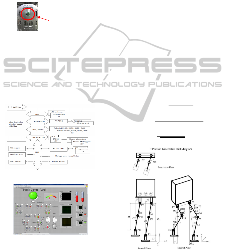
As shown in Figure (8), an absolute accelerometer
sensor is mounted directly on the joint’s shaft to
provide a prefect zero ground homing angle for the
robot with reference to world reference coordinate.
This is a unique features for TPinokio, if the robot
stands on a slope surface, the reading will be
compensated by the IMU sensors.
Figure 8: Accelerometer / Joint shaft mounting.
4 SYSTEM ARCHITECTURE
The hardware schematic configuration of TPinokio
is as shown in Figure (9), the main communication
protocol is based on CANbus.
The GUI is written in LabVIEW, as shown in
Figure (10). LabVIEW is chosen because it is user-
friendly.
Figure 9: Hardware System Configuration.
Figure 10: TPinokio GUI with LabVIEW.
5 KINEMATICS
5.1 Simple Kinematics
TPinokio’s joints and mechanism are designed to
produce simple kinematics structure, due to its
modular-joint design and the links to each joints are
made of light-weight aluminium, the mass and
inertia of the link are negligible compared to the
weight of the modular-joint, and the link is also
assumed to having point-mass located at the distal
end, as shown in Figure (11).
5.2 Inverse Kinematics
The inverse kinematic parameters (Goswami et al.
2009) of TPInokio are as shown in a set of
Equations (1).
=
−
;
=−
;
=
−
=
−
;
=−
;
=
−
=
+
−
+
+
2
=
sin
+
+
=
+
−
+
+
2
=
sin
+
+
(1)
Figure 11: Tpinokio Kinematic Parameters.
The values of the joints’ angle [θ
1
, θ
2,
θ
3, ...
θ
12
]
T
, can
Accelerometer sensor
mounted directly on joint’s
shaft axis to read zero ground
homing position
ICINCO 2011 - 8th International Conference on Informatics in Control, Automation and Robotics
188

be found from these four angular parameters (θ
A
, θ
B,
θ
C,
θ
D
) by solving trigonometric equations.
6 ZERO MOMENT POINT
ZMP is defined as a point on the ground where the
sum of all the moments equals zero. TPinokio ZMP
is obtained by both kinematics and measurement
methods. The values are input to the controller for
further filtering to determine the actual ZMP
location.
6.1 CoM Multi-body Point-mass Model
With the point-mass design, TPinokio CoM
(
,
,
) can be obtained from direct
calculation with the following Equations (2):
=
∑
∑
=
+
+
+
2
+
+
+
+
+
+
+
+
+
And the (
,
) can be calculated with the same
formula,
=
∑
∑
;
=
∑
∑
(2)
The ZMP (
,
,0 ) is related to the CoM by
the following Equations (3).
=
+
∑
−
∑
∑
∑
−
∑
∑
+
∑
∑
∑
∑
(3)
where M
ix
and M
iy
are the moments of the links due
to rotation about x-axes and y-axes, respectively.
6.2 Direct Measurement Model
Direct measurement of ZMP without knowledge of
kinematics is also possible by reading the FSR
sensors feedback values, Figure (7). The position is
calculated by using Equation (4). These values are
used in the controller observer feedback loop for
ZMP error correction.
=
+
−
+
+
+
+
;
=
+
−
+
+
+
+
(4)
6.3 Simplified Inverted Pendulum
Model
The IPM method is a highly simplified model,
during the swing phase, the Center-of-Mass (CoM)
of the robot may be modeled as point-mass and is
connected to the stance foot like an inverted
pendulum, as shown in Figure (13). The simplified
ZMP (
,
,0) can be computed with
Equations (5).
Figure 12: 3D IPM moving cart model.
=
−
(5)
6.4 Dynamic Model of TPinokio
The TPinokio dynamic model is as shown in Figure
(12), the masses are concentrated at the links end,
and the links inertia is assumed to be zero, therefore
Equation (3) may be reduced to:
=
+
∑
−
∑
∑
∑
−
∑
∑
(6)
So, when the robot moves at a slow or constant
speed, the acceleration term become zero, the highly
simplified ZMP can be approximate as:
=
(7)
It can be verified that Equation (5) also yields the
same result.
7 CONTROL ARCHITECTURE
AND GAIT ALGORITHM
The control architectural is as shown in Figure (13).
Biped walking is a periodic phenomenon (
M. Xie
et al. 2009), to implement the desired CoM/ZMP
path, inverse kinematics is required to determine the
individual joints angle, an observer (Astolfi et al.,
2010) may be designed to determine its velocity and
acceleration.
The basic parameters for humanoid walking are
step-length (S), pelvis height (Z), foot lifting height
HUMANOID ROBOT - Modular-Joint Design of a TPINOKIO Bipedal Robot
189
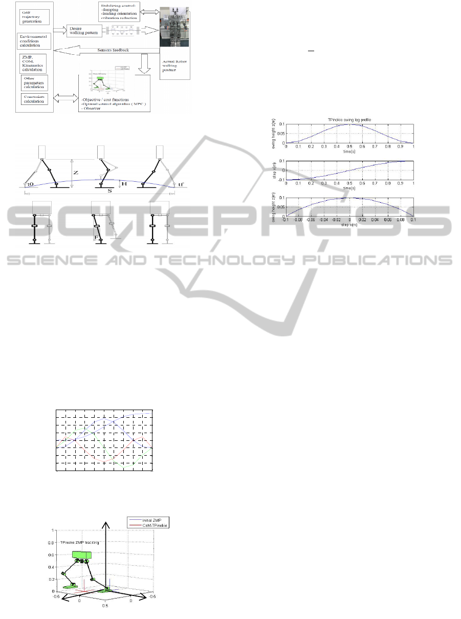
Figure 13: TPinokio Control Scheme / Architecture.
Figure 14: Pelvis / CoM / ZMP motion.
(H) and frontal-shift (F) as shown in Figure (14).
Harmonic and cycloid functions are the most
common paths (
Ill-Woo Park et al., 2006), due to it
simpler expression but with disadvantages due to
nonlinearity. To make a path start and stop with zero
jerk, a seven degree polynomial and eight boundary
conditions must be employed, a zero jerk start-stop
path of a joint moving from 10
o
to 45
o
for t=0 to 1
second, is as shown in Figure (15). The simulation
of ZMP-CoM position tracking is as shown in
Figure (16).
Figure 15: Zero Jerk with Seven Degree Polynomial.
Figure 16: ZMP-CoM tracking simulation.
A simple trajectory that is parabolic, is used for
TPinokio testing of the swing leg foot movement
=−
=
2
1−cos
2
(11)
Where S is the stride (step-length), H is the
maximum foot height, T is the one step period, and
the stride frequency w = π / T. A sample plot of
T=1s, S=0.2m, H=0.1m, is shown in Figure (17).
Figure 17: The Trajectory of the swing foot.
8 CONCLUSIONS
This paper presented and focused on the modular-
joint design concept, the mechanical and hardware
architecture for a new teen-size humanoid robot,
TPinokio. The modular-joint design not only
provides an accurate point-mass model for testing
and simulation, it’s also result in creation of a cost
effective and easy maintenance robot for both
research test bedding and educational learning.
REFERENCES
M. Xie, Z. W. Zhong, L. Zhang, L. B. Xian, L. Wang, H.
J. Yang, C. S. Song and J. Li, A Deterministic Way of
Planning and Controlling Biped Walking of LOCH
Humanoid Robot, International Journal of Industrial
Robot 36/4 (2009), pp 314–325.
Goswami Dip, Vadakkepat Prahlad, Phung Duc Kien,
Genetic algorithm-based optimal bipedal walking gait
synthesis considering tradeoff between stability
margin and speed, Robotica (2009) volume 27, pp.
355-365.
Ill-Woo Park, Jung-Yup Kim, Jungho Lee and Jun-Ho Oh,
Online Free Walking Trajectory Generation for Biped
Humanoid Robot KHR -3(HUBO), Proceedings of the
2006 IEEE International Conference on Robotics and
Automation, May 2006, pp. 1231-1236.
Astolfi, A.; Ortega, R.; Venkatraman, A., Global observer
design for mechanical systems with non-holonomic
constraints, American Control Conference (ACC),
2010, pp. 202 – 207.
http://www.ohmsha.co.jp/data/link/4-274-20058-2/
0 0.1 0.2 0.3 0.4 0.5 0.6 0.7 0.8 0.9 1
-30
-20
-10
0
10
20
30
40
50
zero jerk with s even degree polynomial
time
angle
Jerk
Acceleration
Speed
Position
Z
X
Y
ICINCO 2011 - 8th International Conference on Informatics in Control, Automation and Robotics
190
