
PERFORMANCE VERIFICATION
OF THE HEAD/EYE INTEGRATED TRACKER
Jeong-ho Kim, Dae-woo Lee
Aerospace Department, Pusan National University, Jang-jeon Dong, Pusan City, Korea
Se-jong Heo, Chan-gook Park
Department of Mechanical and Aerospace Engineering, Seoul National University, Seoul City, Korea
Kwang-yul Baek, Hyo-choong Bang
Department of Aerospace Engineering, KAIST, Daejeon City, Korea
Keywords: Head-tracker, Eye-tracker, Integration, Sensor fusion, Dichroic filter.
Abstract: This paper describes the development of an integrated head/eye tracker system. To obtain the position and
attitude of a head, the sensor-fusion head tracker is used. The head tracker combines the result of the vision-
based tracking and the IMU to increase the tracking accuracy. Five sets of IR LEDs are installed on the
surface of a helmet, and the IMU is installed inside the helmet; each set of LEDs comprises three LEDs
positioned at the vertices of a triangle. IR LEDs are used on the eye-tracker system since they are more
suitable than visible LEDs for cognizing the pupil. For the precise tracking of the pupil, three methods—
intensity-based detection method, shape-based detection method, and sequential mean-shift method—are
used. The gaze vector is calculated by using the obtained position of the pupil, focal length, and gaze-point
equation. Finally, we verify whether this integrated system can be used in practical military equipment.
1 INTRODUCTION
In this study, the position and attitude of the head are
measured using an IMU (inertial measurement unit),
which has a high sampling rate, and a vision-based
head tracking method, which guarantees a bounded
error. The experiment is performed on a rate table
and the results of a sensor-fusion algorithm show
that the performance of the integrated system is
better than that of a vision-based tracking system.
In the eye-tracking process, we track the position
of the a pupil using IR(Infrared) LEDs(light-
emitting diodes) and a dichroic filter, which help us
obtain a clear image of the pupil. After obtaining the
position of the pupil, the gaze vector can be
determined using the focal length of the camera and
the relationship between the measured position of
the pupil and the position of the target in the scene
image plane.
When the head tracker and the eye tracker are
not synchronized with each other, the difference
between the measured times may lead to an
erroneous result. Therefore, we use a triggering
signal to prevent such an error. If each system has a
single thread, following the sequence is not a
problem. However, if the system has many threads,
one of the threads may not follow the sequence. In
other words, the system may send a wrong result to
the MCU and tracking will not be accurate. This
paper represents a system set up in a multithreaded
environment. This system can control the operation
sequence of the threads by using the thread
synchronization function. Finally, we evaluate the
appropriateness of the thread synchronization
function by considering the operation sequence of
the threads, time delay for context switching, and the
performance of the integrated head/eye tracker
system.
This paper is subjected into three parts, head-
tracker system, eye-tracker system, integrated
167
Kim J., Lee D., Heo S., Park C., Baek K. and Bang H..
PERFORMANCE VERIFICATION OF THE HEAD/EYE INTEGRATED TRACKER.
DOI: 10.5220/0003527801670172
In Proceedings of the 8th International Conference on Informatics in Control, Automation and Robotics (ICINCO-2011), pages 167-172
ISBN: 978-989-8425-75-1
Copyright
c
2011 SCITEPRESS (Science and Technology Publications, Lda.)
system and each part shows the system and the
experimental results.
2 HEAD-TRACKER SYSTEM
2.1 Configuration of the Head-tracker
The system consists of IR LEDs as optical targets
and an IMU fixed on the helmet; in addition, there is
a stereo camera and a PC equipped with a frame
grabber. Five sets of IR LEDs, with each set
comprising three LEDs arranged in a triangular
fashion, are fixed on the surface of the helmet.
It is necessary to carry out research to determine
the pattern with the minimum number of LEDs for
use in real-time tracking. In this research, five
triangular patterns, which involve a lesser number of
LEDs than hexagonal patterns, are used. The
position and attitude are tracked well despite the
number of LEDs being only three.
Figure 1: Triangular LED patterns.
2.2 Image Processing Algorithm
The image processing algorithm used in the hybrid
head-tracker system performs feature segmentation,
projective reconstruction, and model indexing.
Feature segmentation extracts feature points that
represent the LEDs in the image of each camera. To
obtain the feature points of the LEDs, the obtained
images are sequentially processed with dilation and
binarization techniques for denoising. Finally, the
ROI(Region Of Interest) is extracted from the image
to reduce the computation time, and then ROI is
treated by masking method.
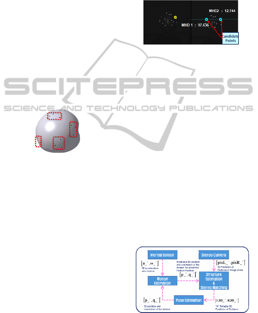
In projective reconstruction, we calculate the 3D
positions of feature points in the camera coordinate
system of the left camera. We establish stereo
correspondence using the epipolar geometry and the
MHD (modified Hausdorff distance). First, the
epipolar constraint is applied to find the candidate
points. This constraint is expressed as
T
qFp=0
,
where F denotes a fundamental matrix and p and q
are homogeneous expression of the position of each
feature point in the image plane. F can be obtained
by camera calibration. The MHD is used to select
the best point among candidate points for stereo
matching. The candidate point with the minimum
MHD is considered the best point for stereo
matching.
Figure 2: Stereo matching.
In model indexing, the point set obtained in
projective reconstruction is matched with a point in
the database using triangle-pattern-based GH
(geometric hashing) and the MHD (Sejong Heo).
The attitude and position of the helmet are
estimated by solving the absolute orientation
problem. In this study, the two coordinate systems
are the helmet coordinate system and camera
coordinate system.
2.3 Estimation of the Position and
Attitude of a Helmet using a Sensor
Fusion Algorithm
In this section, we introduce the fusion system,
which can track the pose, position, and attitude of
the helmet in the world coordinate system by using
the stereo cameras and IMU installed on the helmet.
The indirect method to combine the inertial and
vision data is used and motion and structure
estimation are performed simultaneously. This
implies that no “main” sensor or “aiding” sensor is
used. “Motion” refers to the position, velocity,
acceleration, angular velocity, and attitude of the
helmet, while “structure” refers to the 3D positions
of the feature points (LEDs). Figure 3 shows the
sensor fusion algorithm.
Figure 3: Flowchart of the sensor fusion algorithm.
ICINCO 2011 - 8th International Conference on Informatics in Control, Automation and Robotics
168
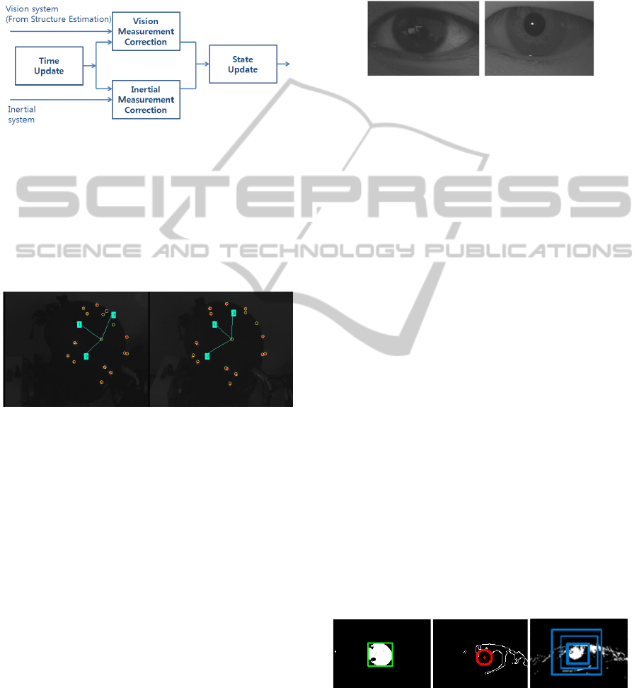
We use the EKF for motion estimation because
we use non-linear system models—non-linear
measurement model of an inertial system and linear
measurement model of a vision system. A block
diagram of the motion estimation filter is shown in
Fig. 4. (Sejong Heo).
Figure 4: Block diagram of the motion estimation filter.
The structure estimation is performed by using a
bank of simple EKFs. Even though new features
appear on or some features disappear from the scene,
the structure estimation algorithm can track the
features robustly. In Fig. 5, the green lines connected
to boxes with the numerals 1, 2, and 3 are the axes
of the helmet coordinate system.
Figure 5: Feature point tracking in the structure estimation
process.
3 EYE-TRACKER SYSTEM
3.1 Configuration of the Eye-tracker
The eye-tracker system is configured by using two
IR module cameras, dichroic filters, one scene
camera, and a PC equipped with a frame grabber.
The dichroic filters reflect infrared radiation and
allow visible radiation to pass through. Thus,
infrared radiation from IR LEDs is reflected to the
eyes and the scene is reflected to the cameras. Thus,
a user can see the front view by using these filters,
without any problem.
3.2 Pupil-tracking Method
In the process of the tracking the pupil, the EKF
(extended Kalman filter) is used. The EKF estimates
and measures the position of the pupil and then
operates only in a small region near the estimated
position. Thus, this process is advantageous for
reducing the computational load without decreasing
accuracy. The circle fitting algorithm and sequential
mean-shift are also used with the EKF.
Figure 6: Clarity of eye when (left) visible radiation and
(right) infrared radiation are used.
3.2.1 Intensity-based Binarization
An image of the pupil is binarized by thresholding
and then processed with a morphological filter to
decrease the noise. In the processed image, groups
of pixels are labelled, and the size, aspect ratio, and
compactness of the labelled object are measured.
3.2.2 Circle-detection based Tracking
The edges of the pupil image are determined by the
Canny edge method. After detecting the edge, we
search for the circular object by using the Hough
transform method. The Canny method is more
accurate than the Sobel and Laplace methods
because it eliminates the small boundary by
measuring the boundary. Circle detection is
conducted using the Hough circle transform with
predefined radius ranges.
3.2.3 Sequential Mean-shift
The sequential mean-shift algorithm repeatedly
performs several mean-shift operations, with the
search region being progressively decreased in every
successive operation. First, a wide region of the
image is searched. The search region is decreased in
every subsequent operation to searching more
accurately. This method is robust against noise like
the eyebrow and eyelid, as shown in right of Fig. 7
Figure: 7 Binarized image of the pupil (left); Edge and
circle detection (middle); Sequential Mean-shift (right).
PERFORMANCE VERIFICATION OF THE HEAD/EYE INTEGRATED TRACKER
169
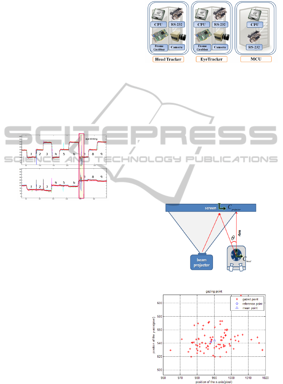
3.3 Experimental Results
We performed experiments using the eye tracker in
real-time environments. In these experiments, the
user gazed at nine points for 30 s. Figure 8 shows
the pupil positions measured by the above-
mentioned pupil-tracking methods and the estimated
positions obtained by using the Kalman filter. The
upper panel gives the X-axis positions of the pupil in
the image plane, and the lower panel gives the Y-
axis positions. The user’s blinks can cause pupil
tracking to fail, as shown at 200 in Fig 8. Even if the
measured position is bounced because of tracking
failure, the estimated position is rapidly stabilized.
The eye-tracker system shows an error within 2
pixels from the centre of a target for free head
motion. We can verify that the experimenter’s gaze
points to the target fairly accurately.
Figure 8: Tracking result for the position of the pupil:
(above) x-axis and (below) y-axis.
4 INTEGRATED TRACKING
SYSTEM DEVELOPMENT
4.1 Experimental Results
The integrated system is configured by using a head-
tracker system, eye-tracker system, and Main
Control Unit (MCU) as shown in Fig. 9.
In this integrated system, synchronization
between the head tracker and eye tracker is very
important for high accuracy. If the two systems are
not synchronized with each other, then each system
obtains the image of the helmet or pupil at different
times and this may lead to an error when a target is
moving fast.
This paper presents a synchronization method that
involves the use of a trigger signal from the MCU.
Using this method, we can synchronize the head-
tracker system and eye-tracker system and integrate
the tracking results from both systems onto an
integrated coordinate. The MCU also provides all
information on a monitor.
Figure 9: Configuration of the integrated system.
The gaze-tracking system has to consider the
relationship between the head and eye. Without this
consideration, gaze tracking that is performed by
making assumptions such as the head or gaze
direction being fixed
4.2 Experimental Results
The experimental equipment consists of the
head/eye-tracker system and a beam projector, as
shown in Fig. 10.
Because it is difficult to determine the centre of
the projector, we define the location of the image
centre as a coordinate origin. It is also necessary to
calibrate the error between an image centre and the
coordinate origin of the head/eye-tracker.
Figure 10: Schematic of the experiment.
Figure 11: Gazing points on the screen.
ICINCO 2011 - 8th International Conference on Informatics in Control, Automation and Robotics
170
4.2.1 Case of One-point Gazing with the
Attitude of the Head Fixed
Figure 11 shows results for the case of one-point
gazing when the attitude of the user’s head is fixed.
The circle indicates the reference (target) point, and
the stars. The errors between the reference point and
the mean value when the user gazes 4 m ahead are
(x, y) = (0.45 cm, 0.37cm) and the standard
deviation is (2.07 cm, 3.06 cm).
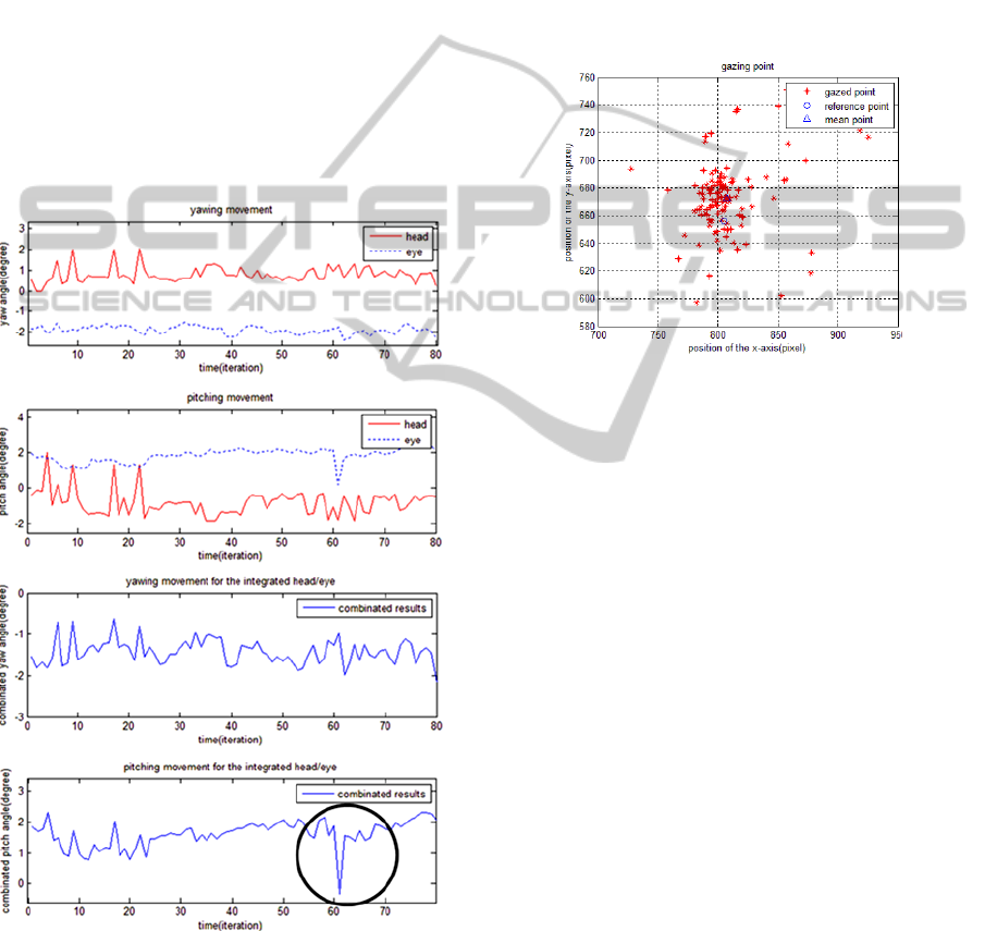
Figure 12 presents the time histories of yaw and
pitch for the head tracker, eye tracker, and integrated
head/eye tracker systems. There are irregular jumps
on the graph for the head tracker compared to the
eye tracker. These jumps occur simultaneously in the
yawing and pitching movements. The reason for the
jumps is the increase or decrease in the number of
LED sets.
Figure 12: Results of the experiment.
The circled part on the graph of pitching
movement for the integrated head/eye integrated
system (fourth graph) dilates on twinkle, which
affects the tracking performance. Besides twinkle,
there are several error factors like difficulty in
maintaining a constant attitude of the head with the
helmet and difficulty in continuously gazing at one
point, etc.
4.2.2 Case of One-point Gazing with
Varying Attitude of the Head
All notations in Fig. 13 are the same as those of Fig.
13. The error between the reference point and mean
value when the user gazes 4 m ahead are (x, y) =
(0.45 cm, 0.325 cm) and the standard deviation is
(5.45 cm, 5.06cm).
Figure 13: Gazing point on the screen.
In this section, we performed an experiment for
the case of one-point gazing with a varying attitude
of the head. The first graph in Fig. 14 shows that
initially, the head is shifted toward the left side by 9°
and the eyes gaze at the centre of the screen. After
32 iterations, the head is turned left by 20°. Finally,
the head is turned right by 8° and the eyeballs move
left by 10°, as shown in the circle in the first graph
of Fig. 14
A positive yaw angle implies right rotation and a
negative yaw angle indicates left rotation. Although
the directions of the head and gaze are opposite,
eyes become gaze at reference point. From these
results, we can verify irregular time histories for
eyes because the user’s eyes are turned away from
the gazing point whenever the head is turned.
Although we try to reduce the pitch movement,
we cannot prevent it because of the structural
characteristics of the neck and head. These errors are
observed as short-period sudden variations and are
unavoidable.
The other factors responsible for short-period
sudden variations are blinks and an increase or
decrease in the number of LED sets in the head-
tracker system, similar to the preceding case. The
errors resulting from an increase or decrease in the
number of LED sets are within 3°.
PERFORMANCE VERIFICATION OF THE HEAD/EYE INTEGRATED TRACKER
171
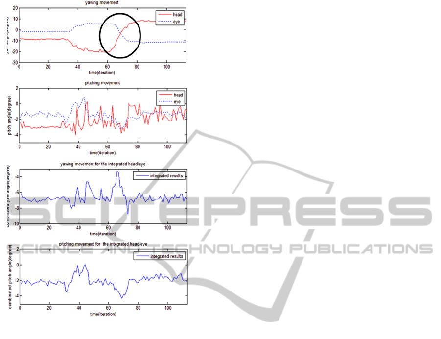
Figure 14: Results of the experiment.
5 CONCLUSIONS
This paper discusses the development of an
integrated head/eye tracker. A user can gaze at a
target during free head motion. The position of the
user’s head and gaze direction can be determined by
using head/eye-tracker system.
The head-tracker and eye-tracker systems
commence operations following the triggering signal
from the MCU; all processed data are stored in the
MCU. The collected data are integrated and
converted to integration coordinates. During the
whole process, all information about tracking is
presented on the screen of the MCU, and a 3-D
model helps understand the state of the user.
The integrated head-tracker system developed in
this study shows a 7-mm error for translation motion
of 0.3 m and 0.0329deg error for the rotation of the
helmet. The eye-tracker system shows an error
within 2 pixels from the centre of a target for free
head motion. The tracking result is indicated by the
cross hair of the scene camera installed on a top of
the helmet on an image captured by it. A 3D model
helps in understanding the tracking status.
As indicated by the experimental results, while
there are small errors in the time histories of the
yaw, there are many short-period sudden variations
in the time histories of the pitch.
The integrated head/eye-tracker system can track
the target continuously when the head is turning.
From this fact, it is clear that this integrated head-
tracker system can be used as an effective substitute
input system.
ACKNOWLEDGEMENTS
This research is supported by vision based collision
avoidance project of the Korean Aerospace Research
Institute(KARI) and thank you for the support.
REFERENCES
Fakhr-eddine Ababsa and Malik Mallem, “Inertial and
Vision Head Tracker Sensor Fusion Using a Particle
Filter for Augmented Reality Systems”, Circuits and
Systems, 2004. ISCAS '04. Proceedings of the 2004
International Symposium in Vol.3, 23–26 May 2004,
pp. 861-4.
Sejong Heo, Okshik Shin, and Chan Gook Park,
“Estimating Motion Parameters of Head by Using
Hybrid Extended Kalman Filter”, ION GNSS, 2009.
Youngil Kim, Youngjun Lee, and Chan Gook Park, “An
Optical Helmet-Tracking System Using EKF-Based
PF”, AIAA Guidance, Navigation and Control
Conference and Exhibit, Honolulu, Hawaii, August
18–21.
D. Comaniciu, V. Ramesh, and P. Meer, “Real-Time
Tracking of Non-Rigid Objects Using Mean Shift”,
Conference on Computer Vision and Pattern
Recognition, 2000.
E. Foxlin, Y. Altshuler, L. Naimark, and M. Harrington,
“FlightTracker: A Novel Optical/Inertial Tracker for
Cockpit Enhanced Vision”, IEEE/ACM International
Symposium on Mixed and Augmented Reality
(ISMAR 2004), Washington, D.C., Nov. 2–5 2004.
ICINCO 2011 - 8th International Conference on Informatics in Control, Automation and Robotics
172
