
HIGH-FREQUENCY ANALYSIS OF PHASE-LOCKED LOOP
AND PHASE DETECTOR CHARACTERISTIC COMPUTATION
N. V. Kuznetsov
1,2
, G. A. Leonov
2
, P. Neittaanm¨aki
2
, S. M. Seledzhi
1
,
M. V. Yuldashev
2
and R. V. Yuldashev
2
1
University of Jyv¨askyl¨a, P.O. Box 35 (Agora), FIN-40014, Jyv¨askyl¨a, Finland
2
Saint-Petersburg State University, Universitetski pr. 28, 198504, Saint-Petersburg, Russia
Keywords:
Nonlinear analysis, Phase-locked loop, Phase detector characteristic, Mathematical model.
Abstract:
Problems of rigorous mathematical analysis of PLL are discussed. An analytical method for phase detec-
tor characteristics computation is suggested and new classes of phase detector characteristics are computed.
Effective methods for nonlinear analysis of PLL are discussed.
1 INTRODUCTION
Phase-locked loop (PLL) systems were invented in
the 1930s-1940s (De Bellescize, 1932; Wendt & Fre-
dentall, 1943) and were widely used in radio and tele-
vision (demodulation and recovery, synchronization
and frequency synthesis). Nowadays PLL can be pro-
duced in the form of single integrated circuit and var-
ious modifications of PLL are used in a great amount
of modern electronic applications (radio, telecommu-
nications, computers, and others).
At present there are several types of PLL (classi-
cal PLL, ADPLL, DPLL, and others), intended for the
operation with different types of signals (sinusoidal,
impulse, and so on). In addition, it is also used differ-
ent realizations of PLL, which are distinct from each
other according to the principles of operation and re-
alization of main blocks.
For the sake of convenience of description, in
PLL the following main functional blocks are consid-
ered: phase detector (PD), low-pass filter (LPF), and
voltage-controlled oscillator (VCO). Note that such a
partition into functional blocks often turns out to be
conditional, since in many cases in particular physi-
cal realization it is impossible to point out the strict
boundaries between these blocks. However these
blocks can be found in each PLL.
The general PLL operation consists in the genera-
tion of an electrical signal (voltage), a phase of which
is automatically tuned to the phase of input (refer-
ence) signal, i.e. PLL eliminates misphasing (clock
skew) between two signals. For this purpose the refe-
rence signal and the tunable signal of voltage-
controlled oscillator are passed through a special non-
linear element — phase detector (PD). The phase
detector produces an error correction signal, corre-
sponding to phase difference of two input signals. For
the discrimination of error correction signal, a signal
at the output of phase detector is passed through low-
pass filter (LPF). The error correction signal, obtained
at the output of filter, is used for the frequency con-
trol of tunable oscillator, the output of which enters a
phase detector, providing thus negative feedback.
The most important performance measure of PLL
is the capture range (i.e. a maximal mistuning range
of VCO, in which a closed contour of PLL stabilizes
a frequency of VCO) and a locking speed (speed of
frequency adjustment).
Thus, when designing PLL systems, an important
task is to determine characteristics of system (involv-
ing parameters of main blocks) providing required
characteristics of operation of PLL.
To solve this problem, it is used real experiments
with concrete realization of PLL as well as the ana-
lytical and numerical methods of analysis of mathe-
matical models of PLL. These tools are used for the
obtaining of stability of required operating modes, the
estimates of attraction domain of such modes, and the
time estimates of transient processes.
Remark, however, that for the strict mathematical
analysis of PLL it should be taken into account the
fact that the above principles of operation of PLL re-
sult in the substantial requirements:
X construction of adequate nonlinear mathemat-
272
V. Kuznetsov N., A. Leonov G., Neittaanmäki P., M. Seledzhi S., V. Yuldashev M. and V. Yuldashev R..
HIGH-FREQUENCY ANALYSIS OF PHASE-LOCKED LOOP AND PHASE DETECTOR CHARACTERISTIC COMPUTATION.
DOI: 10.5220/0003522502720278
In Proceedings of the 8th International Conference on Informatics in Control, Automation and Robotics (ICINCO-2011), pages 272-278
ISBN: 978-989-8425-74-4
Copyright
c
2011 SCITEPRESS (Science and Technology Publications, Lda.)

ical models (since PLL contains nonlinear elements)
in signal space and phase-frequency space
and
X justification of the passage between these mod-
els (since PLL translates the problem from signal re-
sponse to phase response and back again).
Despite this, as noted by well-known PLL ex-
pert Danny Abramovitch in his keynote talk at Amer-
ican Control Conference ACC’2002 (Abramovitch,
2002), the main tendency in a modern literature (see,
e.g., (Egan, 2000; Best, 2003; Kroupa, 2003; Razavi,
2003)) on analysis of stability and design of PLL is
the use of simplified linearized models and the ap-
plication of the methods of linear analysis, a rule of
thumb, and simulation.
However it is known that the application of lin-
earization methods and linear analysis for control
systems can lead to untrue results (e.g., Perron ef-
fects of Lyapunov exponent sign inversion (Leonov
& Kuznetsov , 2007), counterexamples to Aizerman’s
conjuncture and Kalman’s conjuncture on absolute
stability, harmonic linearization and filter hypothe-
sis (Leonov et al., 2010
2
)) and requires special jus-
tifications. Also simple numerical analysis can not
reveal nontrivial regimes (e.g., semi-stable or nested
limit cycles, hidden oscillations and attractors (Gubar,
1961; Kuznetsov & Leonov, 2008; Leonov et al.,
2010
2
; Leonov et. al., 2010
1
; Leonov et. al., 2011)).
2 NONLINEAR MATHEMATICAL
MODELS OF PLL
Various methods for analysis of phase-locked loops
are well developed by engineers and considered in
many publications (see, e.g., (Viterbi, 1966; Gardner,
1966; Lindsey, 1972; Shakhgildyan & Lyakhovkin,
1972)), but the problems of construction of adequate
nonlinear models and nonlinear analysis of such mod-
els are still far from being resolved turn out to be dif-
ficult. and require to use special methods of quali-
tative theory of differential, difference, integral, and
integro-differential equations (Leonov et al., 1996;
Suarez & Quere, 2003; Margaris, 2004; Leonov,
2006; Kudrewicz & Wasowicz, 2007; Leonov et al.,
2009).
In the present paper some approaches to the non-
linear analysis of PLL are described. Nonlinear math-
ematical models of high-frequency oscillations are
presented.
To construct an adequate nonlinear mathematical
model of PLL in phase space it is necessary to find the
characteristic of phase detector. The inputs of PD are
high-frequency signals of reference and tunable os-
cillators and the output contains a low-frequency er-
ror correction signal, corresponding to a phase differ-
ence of input signals. For the suppression of high-
frequency component of the output of PD (if such
component exists) the low-pass filters are applied.
The dependence of the signal at the output of PD
(in phase space) on phase difference of signals at the
input of PD is the characteristic of PD. This char-
acteristic depends on the realization of PD and the
types of signals at the input. Characteristics of the
phase detector for standard types of signal are well-
known to engineers (Viterbi, 1966; Shakhgildyan &
Lyakhovkin, 1972; Abramovitch, 2002).
Further, on the examples of classical PLL with
a phase detector in the form of multiplier, we con-
sider general principles of computing phase detector
characteristics for different types of signals based on
a rigorous mathematical analysis of high-frequency
oscillations (Leonov & Seledzhi , 2005a; Leonov,
2008; Kuznetsov et al., 2008; Kuznetsov et al., 2009
1
;
Kuznetsov et al., 2009
2
; Leonov et al., 2010
3
).
2.1 Description of Classical PLL in the
Signal Space
Consider classical PLL at the level of electronic real-
ization (Fig. 1)
Figure 1: Block diagram of PLL at the level of electronic
realization.
Here OSC
master
is a master oscillator, OSC
slave
is
a slave (tunable voltage-controlled) oscillator, which
generates oscillations f
j
(t) with high-frequencies
ω
j
(t).
Block
N
is a multiplier of oscillations of f
1
(t) and
f
2
(t) and the signal f
1
(t) f
2
(t) is its output. The re-
lation between the input ξ(t) and the output σ(t) of
linear filter has the form
σ(t) = α
0
(t) +
t
Z
0
γ(t − τ)ξ(τ)dτ. (1)
Here γ(t) is an impulse transient function of filter,
α
0
(t) is an exponentially damped function, depend-
ing on the initial data of filter at moment t = 0.
In the simplest ideal case, when
f
1
= sin(ω
1
), f
2
= cos(ω
2
)
f
1
f
2
= [sin(ω
1
+ ω
2
) + sin(ω
1
− ω
2
)]/2,
HIGH-FREQUENCY ANALYSIS OF PHASE-LOCKED LOOP AND PHASE DETECTOR CHARACTERISTIC
COMPUTATION
273

standard engineering assumption is that the filter re-
moves the upper sideband with frequency from the
input but leaves the lower sideband without change.
Thus it is assumed that the filter output is
1
2
sin(ω
1
− ω
2
).
Here to avoid these non-rigorous arguments we
consider mathematical properties of high-frequency
oscillations.
2.2 Computation of Phase Detector
Characteristic
A high-frequency property of signals can be reformu-
lated as the following condition. Consider a large
fixed time interval [0,T], which can be partitioned
into small intervals of the form
[τ,τ + δ], τ ∈ [0,T],
where the following relations
|γ(t) − γ(τ)| ≤ Cδ, |ω
j
(t) − ω
j
(τ)| ≤ Cδ,
∀t ∈ [τ, τ+ δ], ∀τ ∈ [0,T],
(2)
|ω
1
(τ) − ω
2
(τ)| ≤ C
1
, ∀τ ∈ [0, T], (3)
ω
j
(t) ≥ R, ∀t ∈ [0,T] (4)
are satisfied.
We shall assume that δ is small enough relative to
the fixed numbers T,C,C
1
and R is sufficiently large
relative to the number δ : R
−1
= O(δ
2
).
The latter means that on small intervals [τ,τ + δ]
the functions γ(t) and ω
j
(t) are “almost constant”
and the functions f
j
(t) on them are rapidly oscillat-
ing. Obviously, such a condition occurs for high-
frequency oscillations.
Consider now harmonic oscillations
f
j
(t) = A
j
sin(ω
j
(t)t + ψ
j
), j = 1,2, (5)
where A
j
and ψ
j
are certain numbers, ω
j
(t) are dif-
ferentiable functions.
Consider two block diagrams shown in Fig. 2 and
Fig. 3.
Figure 2: Multiplier and filter.
In Fig. 3 θ
j
(t) = ω
j
(t)t + ψ
j
are phases of oscil-
lations f
j
(t), PD is a nonlinear block with the charac-
teristic ϕ(θ). The phases θ
j
(t) are the inputs of PD
Figure 3: Phase detector and filter.
block and the output is the function ϕ(θ
1
(t) − θ
2
(t)).
A shape of phase detector characteristic is based on a
shape of input signals.
The signals f
1
(t) f
2
(t) and ϕ(θ
1
(t) − θ
2
(t)) are in-
puts of the same filters with the same impulse tran-
sient function γ(t). The filter outputs are the functions
g(t) and G(t), respectively.
A classical PLL synthesis for the sinusoidal sig-
nals is based on the following result (Viterbi, 1966):
If conditions (2)–(4) are satisfied and
ϕ(θ) =
1
2
A
1
A
2
cosθ,
then for the same initial data of filter, the following
relation
|G(t) − g(t)| ≤ C
2
δ, ∀t ∈ [0,T]
is satisfied. Here C
2
is a certain number being inde-
pendent of δ.
But what could be done for other types of signal?
Consider now signals in the following form of
Fourier series
f
1
(t) =
∞
∑
i=1
a
i
sin(iθ
1
(t)), f
2
(t) =
∞
∑
j=1
b
j
sin( jθ
2
(t)),
(6)
where
a
k
= O
1
k
, b
k
= O
1
k
, k = 1,2,... .
Let functions f
1
(t) and f
2
(t) are integrable and
bounded on each of the intervals of length δ.
Then the following assertion is valid
Theorem 1. If conditions (2)–(4) are satisfied and
ϕ(θ
1
− θ
2
) =
∞
∑
l=1
a
l
b
l
2
cos(l(θ
1
− θ
2
)), (7)
then for the same initial states of filter the following
relation
|G(t) − g(t)| ≤ C
3
δ, ∀t ∈ [0,T] (8)
is valid.
Proof. Consider a decomposition of the interval [0,T]
into the δ length time intervals. Then using (2) we
ICINCO 2011 - 8th International Conference on Informatics in Control, Automation and Robotics
274

obtain
g(t) − G(t) =
m
∑
k=0
γ(t − kδ)
(k+1)δ
Z
kδ
f
1
θ
1
(s)
f
2
θ
2
(s)
− ϕ
θ
1
(s) − θ
2
(s)
ds+ O(δ).
(9)
Because the frequencies are almost constant in the
δ-intervals (3), we could introduce θ
p
k
(s)
θ
p
k
(s) = ω
p
(kδ)s+ ψ
p
, p ∈ {1,2}.
(10)
Lemma 1. Assuming conditions (2)–(4) the phases
θ
p
(t) could be replaced with θ
p
k
(t)
(k+1)δ
Z
kδ
ϕ
θ
1
(s) − θ
2
(s)
=
(k+1)δ
Z
kδ
ϕ
θ
1
k
(s) − θ
2
k
(s)
ds+ O(δ),
(k+1)δ
Z
kδ
f
1
θ
1
(s)
f
2
θ
2
(s)
=
(k+1)δ
Z
kδ
f
1
θ
1
k
(s)
f
2
θ
2
k
(s)
ds+ O(δ),
(11)
Then, usign Lemma 1, equation (9) can be rewrit-
ten
g(t) − G(t) =
m
∑
k=0
γ(t − kδ)
Z
[kδ,(k+1)δ)
f
1
θ
1
k
(s)
f
2
θ
2
k
(s)
− ϕ
θ
1
k
(s) − θ
2
k
(s)
ds+ O(δ)
(12)
Lemma 2. For the neighborhoodsW
ε,k
of discontinu-
ity points, there is a number M, such that
g(t) − G(t) =
m
∑
k=0
γ(t − kδ)
Z
[kδ,(k+1)δ]\W
ε,k
M
∑
i=1
a
1
i
sin
iθ
1
k
(s)
)
M
∑
j=1
a
2
j
sin
jθ
1
k
(s)
− ϕ
θ
1
k
(s) − θ
2
k
(s)
ds+ O(δ).
Lemma 2 implies
g(t) − G(t) =
m
∑
k=0
γ(t − kδ)
Z
[kδ,(k+1)δ]\W
ε,k
M
∑
i=1
M
∑
j=1
a
1
i
sin
iθ
1
k
(s)
a
2
j
sin
jθ
2
k
(s)
−
− ϕ
θ
1
k
(s) − θ
2
k
(s)
ds+ O(δ).
(13)
It’s obvious, that
sin
iθ
1
k
(s)
sin
jθ
2
k
(s)
=
1
2
cos
iθ
1
k
(s) − jθ
2
k
(s)
− cos
iθ
1
k
(s) + jθ
2
k
(s)
(14)
Lemma 3. Assuming conditions (2)–(4) the follow-
ing equations can be obtained
(k+1)δ
Z
kδ
1
q
cos
p(Rs+ ψ)
ds =
O(δ
2
)
pq
,
(15)
Using (13),(4),(14) and Lemma 3, the theorem
statement can be obtained
g(t) − G(t) = O(δ) . (16)
This result could be easily extended to the case
of full Fourier series and allows one to calculate the
phase detector characteristic in the following standard
cases of signals (Kuznetsov et al., 2010).
Example 1. Two sign signals
f
k
(t) = A
k
sign sin(θ
k
(t)) =
=
4A
k
π
∞
∑
n=0
1
2n+1
sin((2n+ 1)(ω
k
(t)t + ψ
k
)), k = 1,2
ϕ(θ
1
− θ
2
) =
8A
1
A
2
π
2
∞
∑
n=0
1
(2n+1)
2
cos(θ
1
− θ
2
)
−2 pi −pi 0 pi 2 pi
−A1A2
0
A1A2
Θ
← φ(θ)
Figure 4: Phase detector characteristic ϕ(θ) for two sign
signals.
HIGH-FREQUENCY ANALYSIS OF PHASE-LOCKED LOOP AND PHASE DETECTOR CHARACTERISTIC
COMPUTATION
275
Thus, here phase detector characteristic φ(θ) corre-
sponds to 2π-periodic function
A
1
A
2
1−
2|θ|
π
, for θ ∈ (−π, π]. (17)
Example 2. Sin signal and sign signal
f
1
(t) = A
1
sin(θ
1
(t))
f
2
(t) = A
2
sign sin(θ
2
(t)) =
=
4A
2
π
∞
∑
n=0
1
2n+1
sin((2n+ 1)(ω
2
(t)t + ψ
2
))
ϕ(θ
1
− θ
2
) =
2A
1
A
2
π
cos(θ
1
− θ
2
)
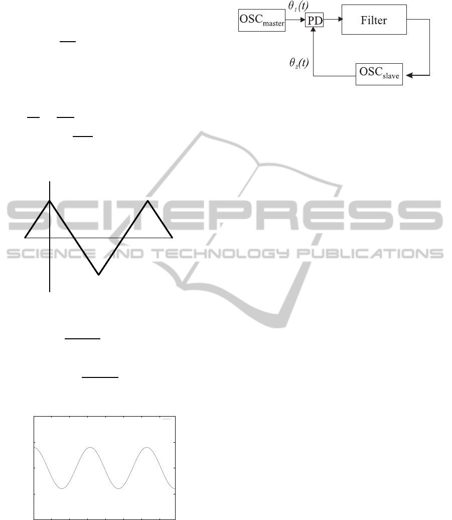
Example 3. Triangle wave signals.
A
0
π
2π
Figure 5: Triangle-wave signal.
f
k
(t) = A
k
∞
∑
i=0
1
(2i− 1)
2
sin
(2i− 1)θ
k
(t)
(18)
ϕ(θ
1
−θ
2
) = A
1
A
2
∞
∑
l=1
1
(2l − 1)
4
cos
(2l−1)(θ
1
−θ
2
)
(19)
-1
-0.5
0
0.5
1
0 2 4 6 8 10 12 14
Figure 6: Phase detector characteristic ϕ(θ) for triangle sig-
nals.
2.3 PLL Equations in Phase-frequency
Space
From Theorem 1 it follows that block-scheme of PLL
in signal space (Fig. 1) can be asymptotically changed
Figure 7: Phase-locked loop with phase detector.
(for high-frequency generators) to a block-scheme at
the level of frequency and phase relations (Fig. 7).
Here PD is a phase detector with corresponding
characteristics. Thus, here on basis of asymptotical
analysis of high-frequency pulse oscillations charac-
teristics of phase detector can be computed.
Characteristic ϕ(θ), computed in Examples 1 and
2, tends to zero if θ = (θ
1
− θ
2
) tends to π/2, so
one can proceed to stability analysis (Leonov, 2006;
Leonov et al., 2009) of differential (or difference)
equations depend on misphasing θ.
Let us make a remark necessary for derivation of
differential equations of PLL.
Consider a quantity
˙
θ
j
(t) = ω
j
(t) +
˙
ω
j
(t)t.
For the well-synthesized PLL such that it possesses
the property of global stability, we have exponential
damping of the quantity
˙
ω
j
(t):
|
˙
ω
j
(t)| ≤ Ce
−αt
.
Here C and α are certain positive numbers indepen-
dent of t. Therefore, the quantity
˙
ω
j
(t)t is, as a rule,
small enough with respect to the number R (see con-
ditions (3)– (4)). From the above we can conclude
that the following approximate relation
˙
θ
j
(t) ≈ ω
j
(t)
is valid. In deriving the differential equations of this
PLL, we make use of a block diagram in Fig. 7 and
exact equality
˙
θ
j
(t) = ω
j
(t). (20)
Note that, by assumption, the control law of tunable
oscillators is linear:
ω
2
(t) = ω
2
(0) + LG(t). (21)
Here ω
2
(0) is initial frequency of tunable oscillator,
L is a certain number, and G(t) is a control signal,
which is a filter output (Fig. 3). Thus, the equation of
PLL is as follows
˙
θ
2
(t) = ω
2
(0) + L
α
0
(t) +
t
Z
0
γ(t − τ)ϕ
θ
1
(τ) − θ
2
(τ)
dτ
.
Assuming that the master oscillator is such that
ω
1
(t) ≡ ω
1
(0), we obtain the following relations for
ICINCO 2011 - 8th International Conference on Informatics in Control, Automation and Robotics
276

PLL
θ
1
(t)−θ
2
(t)
′
+L
α
0
(t) +
t
R
0
γ(t − τ)ϕ
θ
1
(τ)−θ
2
(τ)
dτ
= ω
1
(0) − ω
2
(0).
(22)
This is an equation of standard PLL. Note, that if fil-
ter (1) is an integrating filter with the transfer function
(p+α)
−1
˙
σ+ ασ = ϕ(θ)
then for φ(θ) = cos(θ) in place of of equation (22)
from (20) and (21) we have pendulum-like equation
(Leonov & Smirnova, 1996; Leonov et al., 1996)
¨
˜
θ+ α
˙
˜
θ+ Lsin
˜
θ = α
ω
1
(0) − ω
2
(0)
(23)
with
˜
θ = θ
1
−θ
2
+
π
2
. Thus, if here phases of the input
and output signals mutually shifted by π/2, then the
control signal G(t) equals zero.
Arguing as above, we can conclude that in PLL it
can be used the filters with transfer functions of more
general form K(p) = a+W(p), where a is a certain
number,W(p) is a proper fractional rational function.
In this case in place of equation (22) we have
θ
1
(t) − θ
2
(t)
′
+ L
aϕ
θ
1
(t) − θ
2
(t)
+ α
0
(t)+
+
t
R
0
γ(t − τ)ϕ
θ
1
(τ) − θ
2
(τ)
dτ
= ω
1
(0) − ω
2
(0).
(24)
In the case when the transfer function of the filter
a+W(p) is non-degenerate,i.e. its numerator and de-
nominator do not have common roots, equation (24)
is equivalent to the following system of differential
equations
˙z = Az+ bψ(σ),
˙
σ = c
∗
z+ ρψ(σ).
(25)
Here σ = θ
1
−θ
2
, A is a constant (n×n)-matrix, b and
c are constant (n)-vectors, ρ is a number, and ψ(σ) is
2π-periodic function, satisfying the relations:
ρ = −aL, W(p) = L
−1
c
∗
(A− pI)
−1
b,
ψ(σ) = ϕ(σ) −
ω
1
(0) − ω
2
(0)
L(a+ W(0))
.
The discrete phase-locked loops obey similar
equations
z(t + 1) = Az(t) + bψ(σ(t))
σ(t + 1) = σ(t) + c
∗
z(t) + ρψ(σ(t)),
(26)
where t ∈ Z, Z is the set of integers. Equations
(25) and (26) describe the so-called standard PLLs
(Shakhgildyan & Lyakhovkin, 1972).
For analysis of the above mathematical models
of PLL is applied in the theory of phase synchro-
nization, which was developed in the second half of
the last century on the basis of three applied theo-
ries: the theory of synchronous and induction elec-
trical motors, the theory of auto-synchronization of
the unbalanced rotors, and the theory of phase-locked
loops. Modification of direct Lyapunov method with
the construction of periodic Lyapunov-like functions,
the method of positively invariant cone grids, and the
method of nonlocal reduction turned out to be most
effective (Leonov et al., 1996; Leonov, 2006; Leonov
et al., 2009). The last method, which combines the
elements of direct Lyapunov method and bifurcation
theory, allows one to extend the classical results of
F. Tricomi (Tricomi , 1933) and his progenies (Ku-
drewicz & Wasowicz, 2007) to the multidimensional
dynamical systems.
3 CONCLUSIONS
Considered above methods for high-frequency analy-
sis of PLL allow one to construct adequate nonlinear
dynamical model of PLL and to apply special meth-
ods of qualitative theory of differential, difference, in-
tegral, and integro-differential equations for PLL de-
sign.
ACKNOWLEDGEMENTS
This work was supported by Academy of Finland,
Ministry of Education and Science (Russia) and
Saint-Petersburg State University.
REFERENCES
Abramovitch D., Phase-Locked Loops: A control Centric
Tutorial. Proceedings of the American Control Con-
ference, Vol. 1, pp. 1–15, 2002.
Best R.E., Phase-Lock Loops: Design, Simulation and Ap-
plication. McGraw Hill, 5
ed
, 2003.
De Bellescize H. La Reseption synchrone. Onde Electrique,
Vol. 11, 1932.
Egan W.F., Frequency Synthesis by Phase Lock. John Wiley
and Sons, 2
ed
, 2000.
Gardner F.M., Phase–lock techniques. John Wiley, New
York, 1966.
Gubar’ N.A., Investigation of a piecewise linear dynamical
system with three parameters. J. Appl. Math. Mech,
25, pp. 1519–1535, 1961.
Kudrewicz J. & Wasowicz S., Equations of Phase-Locked
Loops: Dynamics on the Circle, Torus and Cylinder.
World Scientific, Singapure, 2007.
HIGH-FREQUENCY ANALYSIS OF PHASE-LOCKED LOOP AND PHASE DETECTOR CHARACTERISTIC
COMPUTATION
277

Kuznetsov N.V., Leonov G.A., Neittaanmaki P.,
Seledzhi S.M., Yuldashev M.V., Yuldashev R.V.,
Nonlinear analysis of phase-locked loop. 4th Inter-
national Workshop on Periodic Control Systems,
2010.
Kuznetsov N.V., Leonov G.A., Seledzhi S.M., Nonlinear
analysis of the Costas loop and phase-locked loop
with squarer. Proceedings of the IASTED Interna-
tional Conference on Signal and Image Processing,
SIP 2009, pp. 1–7, 2009.
Kuznetsov N.V., Leonov G.A., Seledzhi S.M., Neit-
taanm¨aki P., Analysis and design of computer archi-
tecture circuits with controllable delay line. ICINCO
2009, Proceedings, Vol. 3 SPSMC, pp. 221–224,
2009.
Kuznetsov N.V., Leonov G.A. Lyapunov quantities, limit
cycles and strange behavior of trajectories in two-
dimensional quadratic systems, Journal of Vibroengi-
neering, Vol. 10, Iss. 4, pp. 460-467, 2008.
Kuznetsov N.V., Leonov G.A., Seledzhi S.M. Phase Locked
Loops Design And Analysis. ICINCO 2008 - 5th
International Conference on Informatics in Con-
trol, Automation and Robotics, Proceedings SPSMC,
pp. 114–118, 2008.
Kroupa V. Phase Lock Loops and Frequency Synthesis.
John Wiley & Sons, 2003.
Leonov G.A., Kuznetsov N.V., Vagaytsev V.I. Localization
of hidden Chua’s attractors. Physics Letters A, 2011
(doi:10.1016/j.physleta.2011.04.037)
Leonov G.A., Vagaitsev V.I., Kuznetsov N.V., Algorithm
for localizing Chua attractors based on the harmonic
linearization method // Doklady Mathematics, 82(1),
pp. 663–666, 2010.
Leonov G.A., Bragin V.O., Kuznetsov N.V., Algorithm for
Constructing Counterexamples to the Kalman Prob-
lem. Doklady Mathematics, Vol. 82, No. 1, pp. 540–
542, 2010.
Leonov G.A., Seledzhi S.M., Kuznetsov N.V., P. Neit-
taanm¨aki., Asymptotic analysis of phase control sys-
tem for clocks in multiprocessor arrays, ICINCO 2010
- Proceedings of the 7th International Conference on
Informatics in Control, Automation and Robotics, Vol.
3, pp. 99–102, 2010.
Leonov G.A., Kuznetsov N.V., Seledzhi S.M. Nonlinear
Analysis and Design of Phase-Locked Loops. pp. 89–
114. In Automation control - Theory and Practice,
A.D. Rodic (ed.), In-Tech, 2009.
Leonov G.A., Computation of phase detector characteris-
tics in phase-locked loops for clock synchronization.
Doklady Mathematics, 78(1), pp. 643–645, 2008.
Leonov G.A., Kuznetsov N.V., Time-Varying Lineariza-
tion and the Perron effects. Int. J. of Bifurcation and
Chaos, 17(4), pp. 1079–1107, 2007.
Leonov G.A.. Phase synchronization: Theory and ap-
plications. Automation and remote control, 67(10),
pp. 1573–1609, 2006.
Leonov G.A. & Seledghi S.M., Stability and bifurcations of
phase-locked loops for digital signal processors. Int. J.
of bifurcation and chaos, 15(4), pp. 1347–1360, 2005.
Leonov G.A. & Seledzhi S.M., An astatic phase-locked
system for digital signal processors: Circuit design
and stability. Automation and Remote Control, 66(3),
pp. 348–355, 2005.
Leonov G.A., Ponomarenko D., and Smirnova V.,
Frequency-Domain Methods for Nonlinear Analysis.
Theory and Applications. World Scientific, Singapore,
1996.
Leonov G.A., Smirnova V.B., Stability and oscilla-
tions of solutions of integro-differential equations of
pendulum-like systems. Mathematische Nachrichten,
177, pp. 157–181, 1996.
Lindsey W., Synchronization systems in communication and
control. Prentice-Hall. New Jersey, 1972.
Margaris N.I., Theory of the Non-Linear Analog Phase
Locked Loop. Springer Verlag, 2004.
Razavi B., Phase-Locking in High-Performance Systems:
From Devices to Architectures. John Wiley & Sons,
2003.
Shakhgil’dyan V.V.& Lyakhovkin A.A., Sistemy fazovoi av-
topodstroiki chastoty (Phase Locked Systems). Svyaz’,
Moscow, 1972. (in Russian)
Suarez A. & Quere R., Stability Analysis of Nonlinear Mi-
crowave Circuits. Artech House, 2003.
Tricomi F., Integrazione di differeziale presentasi in elec-
trotechnica. Annali della Roma Schuola Normale Su-
periore de Pisa, Vol. 2, N2, pp. 1–20, 1993.
Viterbi A.J., Principles of coherent communications.
McGraw-Hill, New York, 1966.
Wendt K.R. & Fredentall G.L., Automatic frequency and
phase control of synchronization in TV receivers. Pro-
ceedings IRE, 31, N1, 1943.
ICINCO 2011 - 8th International Conference on Informatics in Control, Automation and Robotics
278
