
FINGERPRINT INDOOR POSITION SYSTEM
BASED ON OPENMAC
A.Verónica Medina, José A. Gómez, Octavio Rivera, Enrique Dorronzoro and Manuel Merino
Departamento Tecnología Electrónica, Seville University, ETSI-Informática, Avda. Reina Mercedes s/n, Seville, Spain
Keywords: IEEE 802.15.4, RSSI, Centroid, Indoor position, ZigBee, WSN.
Abstract: This paper presents a work in progress for the developing of a fingerprint indoor position system based on
OpenMAC, an IEEE 802.15.4 embedded software implementation from Atmel to be used in different
scenarios like e_health, ambient living or smart building. The system is thought to work as another one that
we have yet developed but using the BitCloud Stack, a full-featured, second generation embedded software
stack from the same supplier, but improving it. The first steps followed up in the system development are
shown in this paper.
1 INTRODUCTION
WSNs (Wireless sensor Network) are present in
many applications. They are used in Ambient Living
(Hristova,2008); (Figueiredo, 2010); (Hong 2008);
(Sun 2009) or Smart building (Martin, 2009);
(Dietrich, 2010); (Chen, 2010); (Han, 2010);
(Snoonian, 2003) researching fields for solving data
acquisition process, depending on its applications, it
can be used ambient or user sensors and actuators
for making decisions. The knowledge of the
subject's position it is very useful in this kind of
systems because depending on it the decisions to be
made are different.
As stated in (Konrad, 2005, 2006), a number of
indoor location tracking systems have been proposed
in the literature, based on RF signals, ultrasound,
infrared, or some combination of modalities. Given a
model of radio signal propagation in a building or
other environment, received signal strength can be
used to estimate the distance from a transmitter to a
receiver, and thereby triangulate the position of a
mobile node. However, this approach requires
detailed models of RF propagation and does not
account for variations in receiver sensitivity and
orientation.
An alternative approach is to use empirical
measurements of received radio signals, known as
RSSI, Receiver Signal Strength Indicator, to
estimate location. By recording a database of radio
‘‘signatures’’ along with their known locations, a
mobile node can estimate its position by acquiring a
signature and comparing it to the known signatures
in the database, also known as fingerprints. A
weighting scheme can be used to estimate location
when multiple signatures are close to the acquired
signature
All of these systems require that the signature
database are collected manually prior to system
installation, and rely on a central server (or the
user’s mobile node) to perform the location
calculation. Several systems have demonstrated the
viability of this approach, one of those is MoteTrack
(Konrad, 2005, 2006).
MoteTrack’s basic location estimation uses a
signature based approach that is largely similar to
RADAR (Bahl, 2000) that obtains a 75th percentile
location error of just under 5 m, but decreased the
location error by 1/3 in MoteTrack.
We implemented (Medina, 2011) a system
similar to MoteTrack, a signature-based localization
scheme, but using other motes, Meshnetics´ one
(http://www.meshnetics.com/), that uses different
RCB (MCU and transceiver) and, also, different
software, i. e., the BitCloud Stack, a ZigBee PRO
certified platform. That system was tested and had
the same precision as MoteTrack, but it has some
drawbacks that are going to be solved using the
OpenMAC indeed of BitCloud Stack, both
embedded software developed by Atmel(Atmel have
acquired MeshNetics´s ZigBee Intellectual
Properties).
In Section 2 an overview of the system is
presented. BitCloud Implementation is shown in The
47
Medina A., Gómez J., Rivera O., Dorronzoro E. and Merino M..
FINGERPRINT INDOOR POSITION SYSTEM BASED ON OPENMAC.
DOI: 10.5220/0003517100470052
In Proceedings of the International Conference on Wireless Information Networks and Systems (WINSYS-2011), pages 47-52
ISBN: 978-989-8425-73-7
Copyright
c
2011 SCITEPRESS (Science and Technology Publications, Lda.)
two drawbacks of BitCloud are solved this way. In
OpenMAC solution, mobile motes are EDs The two
drawbacks of BitCloud are solved this way. In
OpenMAC solution, mobile motes are EDs 3.
OpenMAC solution is explained in section 4.
Conclusions are established in section 5.
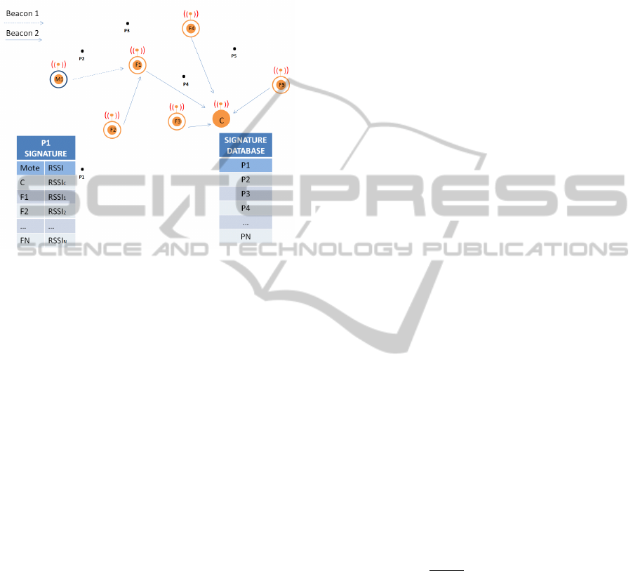
Figure 1: System Overview. M1 is a mobile node, F1-F5
are fixed nodes, and C is the coordinator, also a fixed
node. M1 periodically sends a beacon message, beacon 1,
to inform the others node that is present, all fixed node
that receives it, save the RSSI of that message in a table.
Fixed node periodically sends a message to C, beacon 2, to
inform about the RSSI that they receive from mobiles
node, M1 in this case.
2 SYSTEM OVERVIEW
In this section we give an overview of the system,
shown in Figure 1, that is based on low-power,
embedded wireless devices, MeshNetics´s sensor
“motes”. The advantages of this platform over other
motes is that it´s equipped with extra sensors and
others could be easily connected to them if the
application requires it, so for prototyping these
motes work quite well. Other advantage of this mote
is that the supplier has developed the ZigBee RFC4
stack architecture (ZigBee, 2009) in a software pack
called BitCloud Stack and also the IEEE 802.15.4 in
a software pack called OpenMAC.
In our system, a building or an area is populated
with a number of MeshNetics´s motes acting as
fixed nodes, one of them acting as coordinator, C.
Fixed nodes send to C periodic beacon messages,
beacon 2, which consist of an n-tuple of the format
{MobileID, RSSI}, where n is the number of mobile
nodes. MobileID is a unique identifier of a mobile
node, and RSSI the value received from the last
beacon message, beacon 1, received from that
mobile node in a specific fixed node.
The location estimation problem consists of a
two-phase process: an offline collection of reference
signatures followed by online location estimation.
As in other signature-based systems, the reference
signature database is acquired manually by a user
with a mobile node and a PC connected to C. Each
reference signature, shown as black dots in Figure 1,
consists of a set of signature tuples of the form
{sourceID, meanRSSI}, where sourceID is the fixed
node ID and meanRSSI is the mean RSSI of a set of
beacon messages received over some time interval.
Each signature is mapped to a known location by the
user acquiring the signature database (P1-P5 in
Figure 1).
2.1 Location Estimation
Given a mobile node’s received signature, s,
received from the fixed nodes, and the reference
signature set R, the mobile node’s location can be
estimated as follows. The first step is to compute the
signature distances, from s to each reference
signature r
i
ϵ R. We employ the Manhattan distance
metric,
M(r, s) =
∑
|
∈
RSSI(t)r-RSSI(t)s |
(1)
where T is the set of signatures tuples presented
in both signature, RSSI(i)r is the RSSI value in the
signature appearing in signature r
i
and RSSI(i)s is
the RSSI value in the signature appearing in
signature s.
Given the set of signature distances, the location
of a mobile node can be calculated in several ways.
We consider the centroid of the set of signatures
within some ratio of the nearest reference signature.
Given a signature s, a set of reference signatures R,
and the nearest signature r* = argminr ϵ R M(r, s),
we select all reference signatures r ϵ R that satisfy
(,)
(∗,)
< c
(2)
for some constant c, empirically-determined. The
geographic centroid of the locations of this subset of
reference signatures is then taken as the mobile
node’s position. Small values of c work well,
generally between 1.1 to 1.2.
3 BITCLOUD
IMPLEMENTATION
The BitCloud implementation was developed in a
WINSYS 2011 - International Conference on Wireless Information Networks and Systems
48
Meshbean development board. We have used this
mote because they have leds, buttons, additional
sensors and can easily be connected other sensors
that can be used for different purpose applications of
the indoor position system, ambient living and smart
buildings, so for prototyping works quite well. They
also have a USART accessible by a USB connector,
so a PC can be connected via USB port, emulating
it a COM port, for both programming and receiving
information, in our case beacons and sensor values.
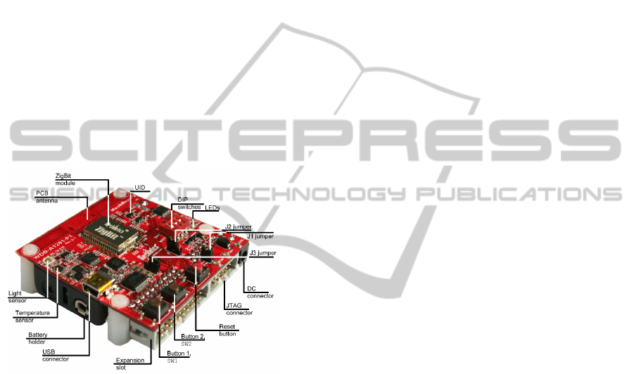
A MeshNetics´s mote is shown in Figure 2, in
this case, it has an integrated PCB antenna, but we
have used others that aren´t, this affects only the
range of coverage. This mote has a MCU wireless,
called ZigBit, a compact 802.15.4/ZigBee module
featuring record-breaking range performance and
exceptional ease of integration. It integrates both the
ATmega1281 microcontroller and AT86RF212
transceiver of ATMEL (www.atmel.com) so the
AVR tools are necessary for programming purposes.
Figure 2: Meshbean development board.
In ZigBee there are three kinds of devices, each
one having its own purpose:
1. Coordinator (C): A full function device
(FFD) that it is in charge of creating the PAN
(Personal Area Network) and typically is the point
of the WSN to acquire all sensors information from
all the other motes to be shown in a computer. The
icon uses to represent this device is a filled circle,
Figure 1 shown one.
2. Router (R): A FFD that it is in charge of
routing when the range of coverage requires this
capability, so it is possible to have dynamic
topologies. The icon uses to represent this device is
a small filled circle inside a circle, Figure 1 shown
six ones.
3. End device (ED): A reduced function
device (RFD) that is always slept (to reduce
consumption) and only wakes up to do a specific
task, for instance, to send sensor information to the
WSN, typically directed towards C. The icon use is a
not filled circle, this is, like the R icon in Figure 1,
but no filled circle inside (Figure 7).
So a ZigBee WSN is composed of one C, many
EDs and many Rs. Each kind of devices can receive
what the other transmit, if they are in the same range
of coverage, because the transmission media is share
by all one, but not all the information receive is
processed (the explanation of why this is that way is
out of the scope of this paper).
As explained in the previous section, to determinate
position, we require to kinds of beacons, beacon1
and beacon2. Beacon 1 is used to inform other
devices that a mobile mote is present and beacon2 is
used to inform C the RSSI value that a fixed mote
receives from a mobile one for location estimation.
To send both beacons in BitCloud Stack, we have to
use the information saved in a table at the network
layer called neighbor table. This table registered all
the FFD, this is, motes that are C o R, that are in the
range of coverage of a determinated mote and for
each one it registers the RSSI value of the received
signal from that mote. Periodically, a FFD device
sends a MAC layer message to inform other that is
in the PAN, so that message is used by neighbor
motes to measure the RSSI value of the received
signal and to save it in their own neighbor table. So
beacon 1 is sent automatically by the protocol stack.
As only FFD sends this kind of message the mobile
motes have to be R, as shown in Figure 1.
To send periodically beacon 2 messages, each
fixed motes search in its neighbour table to find out
if the mobile mote is in its range of coverage, if so,
the beacon 2 is sent to C with the information
required as explained in section 2. As neighbour
table is only in FFD, fixed motes have also to be R.
We deployed BitCloud solution over half floor
of our Department Area, measuring roughly 225 m.
To cover all this area we required 7 fixed motes
strategically placed. An off-line phase was required
to fill in the signature database, once it was full, the
system was ready to be tested.
Figure 3 shows the PC interface to show mobile
mote position, four in this case. It also shows the
mobile mote sensor information.
Although results were as expected as shown in
(Medina, 2011), this solution has two drawbacks, in
order to fix it correctly:
1. The mobile node has to be FFD so the power
consumption is very high and it is a problem because
mobile node is battery power.
2. The periodicity of beacon 1 messages can´t be
controlled as it is a MAC parameter not accessible
by BitCloud Stack.
FINGERPRINT INDOOR POSITION SYSTEM BASED ON OPENMAC
49
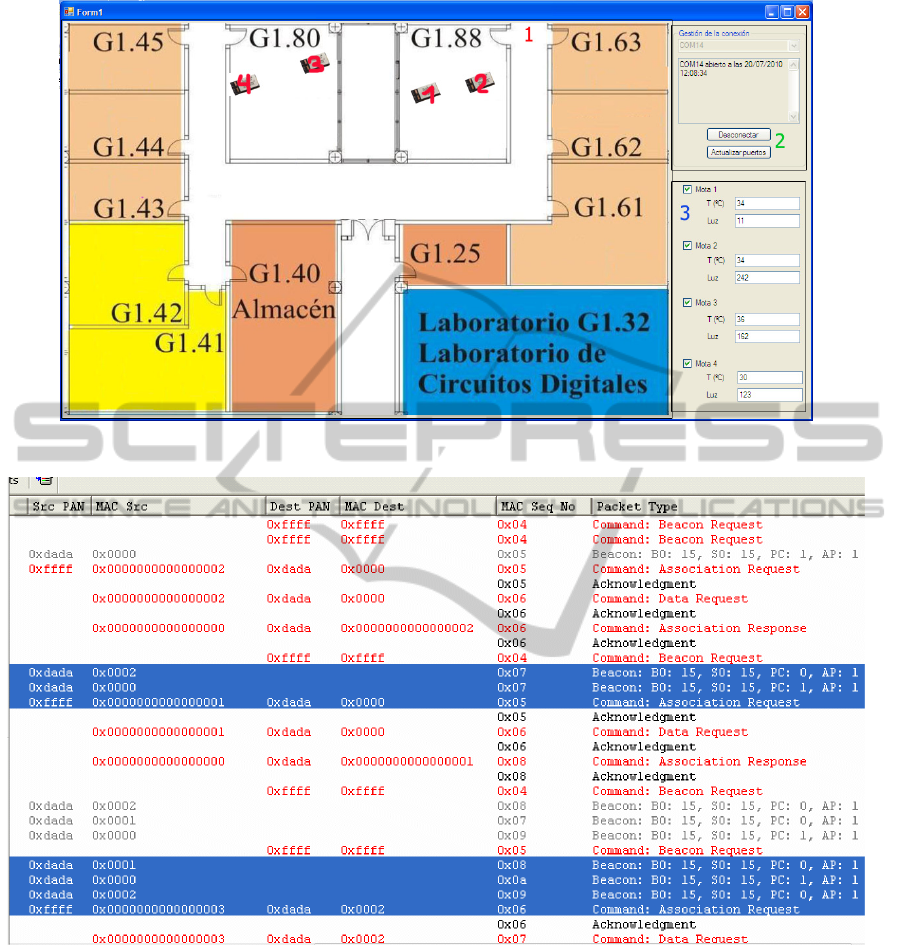
Figure 3: Position System Interface.
Figure 4: Dantree Network Sensor Analyzer Output.
4 OpenMAC IMPLEMENTATION
OpenMAC is an open source implementation of
IEEE802.15.4 Media Access Control (MAC) layer.
It has a series of advantage over using BitCloud
Stack:
1. Enables users, who do not require full
functionality of BitCloud Stack, to develop custom
WSN applications.
2. Enabled advanced users to modify OpenMAC
internals to suit specific application needs.
3. Jump start application development on top of
MAC with thoroughly documented sample
applications.
3. Provide a convenient C API to developers not
familiar with TinyOS or nesC programming
language (technologies at the core of OpenMAC).
4. Provide a reference design to be ported to
analogous hardware platforms.
WINSYS 2011 - International Conference on Wireless Information Networks and Systems
50
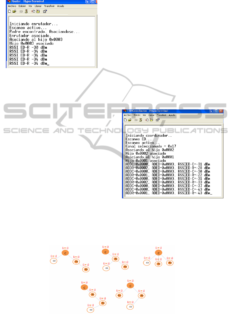
Figure 5: Hyperterminal Output, Beacon 1 Message.
To deploy the same indoor solution as in
BitCloud Stack, it is necessary to create a PAN like
the one shown in Figure 1, where there are all the
kinds of ZigBee devices, C, R and ED and all
implement the same functionally (FFD C and R,
RFD ED). So, C creates the PAN and the other
devices connect to the PAN. All communication
flow is towards the C, so R is in charge of
forwarding packed when other Rs or EDs required,
they are closer to it than to C. R and ED connect to
the PAN via C or other R that is already in the PAN.
To create the PAN, the MAC services
implemented in OpenMAC for doing so, has been
used. There is a bug in the OpenMAC software that
couldn´t be solved. When a R or ED tries to connect
to a PAN, it can decide which device is going to be
its father basing its decision in the RSSI of the
beacon frame, a MAC layer service. As shown in
Figure 4, although there are more than one device
that send the beacon frame when it is requested, the
OpenMAC software only offers as father, the one
that sent the last, but that couldn´t be the best one. In
the lab test, this is not a problem, because all mote
are close, but maybe it will be a problem when we
will deploy the fixed mote, this is something that
will be tested.
The two drawbacks of BitCloud are solved this way.
In OpenMAC solution, mobile motes are EDs not R,
so they are slept all the time and are only woken up
when they have to send beacon 1 message, we
control the frequency of transmission. This message
is broadcasted, so all its neighbours are able to save
the RSSI value of the received message, this
information is required to inform C after. Figure 5
shows the output of a R that is receiving Beacon 1
messages from an ED (mobile mote), they are shown
as "RSSI ED-R".
Periodically, R sends beacon 2 message to C.
This message is unicast, so a R that receives one, has
to forward it, if the source R is one of its child.
Figure 6 shows the output of C that is receiving
Beacon 2 message from a R (fixed mote), they are
shown as "RSSI ED-X", where X is C or R
depending on the sender.
Figure 6: Hyperterminal Output, Beacon 2 Message.
Different scenarios (topologies) has been tested
(Figure 7) in order to prove that the PAN works
correctly and is set to deploy it over the half flour of
our Department. So the following work is to do the
same steps as we did with BitCloud Stack.
Figure 7: Topologies Tested. The blue lines show node´s father.
FINGERPRINT INDOOR POSITION SYSTEM BASED ON OPENMAC
51

5 CONCLUSIONS
The PAN infrastructure for an indoor position
system based on fingerprints is developed using
OpenMAC in a lab environment. The two beacon
messages required for the position estimation has
been implemented. Next step will be to reuse all the
source code implemented in the PC for BitCloud
positioning solution. For doing so some setting has
to be done in other to send the same way the
information from the PAN towards the PC
connected to the C. Once solve, an off-line phase is
required to fill in the signature database. Then the
system will be ready to be fixed and tested.
ACKNOWLEDGEMENTS
This work has been carried out within the
framework of two research programs: (P08-TIC-
3631) – Multimodal Wireless interface (IMI) funded
by the Regional Government of Andalusia and
Efficient and Health Intelligent Technologies
Oriented to Health and comfort in Interior
Environments (TECNO-CAI) approved project at
the fifth call of CENIT program by the Innovation
Science Ministry of Spain (CDTI and Ingenio 2010
Program).
REFERENCES
Hristova, A.; Bernardos, A. M.; Casar, J. R. 2008.
Context-aware services for ambient assisted living: A
case-study. Applied Sciences on Biomedical and
Communication Technologies, 2008. ISABEL '08.
First International Symposium on.
Figueiredo, C. P.; Gama, O. S.; Pereira, C. M.; Mendes, P.
M.; Silva, S.; Domingues, L.; Hoffmann, K.-P. 2010
Autonomy Suitability of Wireless Modules for
Ambient Assisted Living Applications: WiFi, ZigBee,
and Proprietary Devices. Sensor Technologies and
Applications (SENSORCOMM).
Hong Sun; De Florio, V.; Ning Gui; Blondia, C., Towards.
2008. Building Virtual Community for Ambient
Assisted Living. Parallel, Distributed and Network-
Based Processing. 16th Euromicro Conference on.
Sun, H.; De Florio, V.; Gui, N.; Blondia, C., 2009.
PRomises and Challenges of Ambient Assisted Living
Systems. Information Technology: New Generations,
2009. ITNG '09. Sixth International Conference on.
Page(s): 1201 - 1207.
Martin, H.; Bernardos, A. M.; Bergesio, L.; Tarrio, P.,
2009. Analysis of key aspects to manage wireless
sensor networks in ambient assisted living
environments. Applied Sciences in Biomedical and
Communication Technologies, 2009. ISABEL 2009.
2
nd
International Symposium. Page(s): 1 - 8.
Dietrich, D.; Bruckner, D.; Zucker, G.; Palensky, P. 2010.
Communication and Computation in Buildings: A
Short Introduction and Overview. Volume: 57 , Issue:.
Chen, Po-Wei; Ou, Kuang-Shun; Chen, Kuo-Shen. 2010.
IR indoor localization and wireless transmission for
motion control in smart building applications based on
Wiimote technology. SICE Annual Conference 2010.
Han Chen; Chou, P.; Duri, S.; Hui Lei; Reason, J. 2009.
The Design and Implementation of a Smart Building
Control . Page(s): 255 - 262.
Snoonian, D , Smart buildings. 2003. Spectrum, IEEE
Volume: 40, Issue: 8 Digital Object Identifier:
10.1109/MSPEC. Page(s): 18 - 23.
Bahl P., Padmanabhan V. N. 2000. RADAR: an in-
building RF-based user location and tracking system.
In: INFOCOM, pp 775–784.
Konrad L. and Matt W. 2005. MoteTrack: A Robust,
Decentralized Approach to RF-Based Location
Tracking. In: Proceedings of the International
Workshop on Location and Context-Awareness (LoCA
2005) at Pervasive May 2005.
Konrad L., Matt W. 2006. MoteTrack: A Robust,
Decentralized Approach to RF-Based Location
Tracking. To Appear in Springer Personal and
Ubiquitous Computing, Special Issue on Location and
Context-Awareness. . ISSN: 1617-4909 (Print.
Medina A. V., Gómez I., Romera M., Gómez J. A. and
Dorronzoro E. 2011. Indoor Position System based on
BitCloud Stack for Ambient Living and Smart
Buildings. In: 3rd International ICST Conference on
IT Revolutions. Córdoba, Spain.
ZigBee, 2009 RF4CE Specification. Version 1.00. ZigBee
Document 094945r00ZB, March 17th, 2009.
WINSYS 2011 - International Conference on Wireless Information Networks and Systems
52
