
3D VISUALIZATION OF SINGLE IMAGES USING PATCH
LEVEL DEPTH
Shahrouz Yousefi, Farid Abedan Kondori and Haibo Li
Department of Applied Physics and Electronics, Ume˚a University, 901 87, Ume˚a, Sweden
Keywords:
3D Visualization, Monocular Image, MRF, Depth Map, Color Anaglyph.
Abstract:
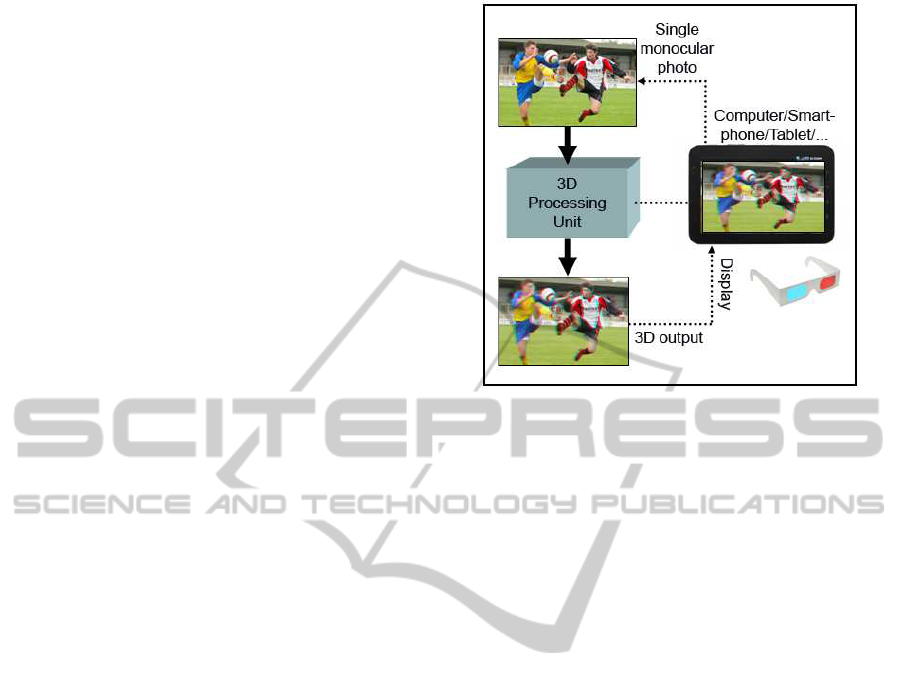
In this paper we consider the task of 3D photo visualization using a single monocular image. The main idea is
to use single photos taken by capturing devices such as ordinary cameras, mobile phones, tablet PCs etc. and
visualize them in 3D on normal displays. Supervised learning approach is hired to retrieve depth information
from single images. This algorithm is based on the hierarchical multi-scale Markov Random Field (MRF)
which models the depth based on the multi-scale global and local features and relation between them in a
monocular image. Consequently, the estimated depth image is used to allocate the specified depth parameters
for each pixel in the 3D map. Accordingly, the multi-level depth adjustments and coding for color anaglyphs
is performed. Our system receives a single 2D image as input and provides a anaglyph coded 3D image in
output. Depending on the coding technology the special low-cost anaglyph glasses for viewers will be used.
1 INTRODUCTION
Nowadays 3D rendering and visualization are terms
which have frequently been encountered in the dis-
cussions of computer vision and graphics. 3D cap-
turing and display devices are becoming popular and
3D cinemas and movies have attracted a lot of atten-
tion during the recent years. Speed of change in the
electronic market is substantially high and selection
of a product among various brands and prices is quite
difficult. Most people are concerned about the money
they spend on a product which they think that might
be useless or out of technology in the near future. On
the other hand, many people are not willing to spend
their money on changing their devices year by year.
For recording and visualization of photos and videos
in 3D, expensive stereo cameras and 3D display de-
vices are available in the market.
Here the question is whether it is possible to find a
simple, efficient and cost-effective way to make use
of ordinary capturing and display devices to visualize
the content in 3D?
What we present in this paper is a novel approach
which enables us to use our normal 2D digital cam-
eras, mobile phones, tablet PCs or any other captur-
ing devices as a 3D camera and display. Our 3D ren-
dering and visualization algorithm heavily relies on
recovering depth from single monocular images cap-
tured by an ordinary camera. Depth modeling from
single images is based on the hierarchical, multi-scale
Markov Random Field (MRF) (Saxena et al., 2005).
Supervised learning approach is used to train the pa-
rameters of the depth model from single images and
the corresponding ground truth depth maps. Hence
the trained system is used to recover the depth from
monocular still images. The main goal of this work
is to make use of this depth map for 3D visualization
of single photos. At this step our algorithm receives
the depth map and automatically adjusts the 3D visu-
alization parameters for all the pixels. Afterwards, it
will be coded into two different channels for 3D visu-
alization in color anaglyphs (Mcallister et al., 2010;
Dubois, 2001). The 3D rendered result can be dis-
played on any normal screen and users simply need
to wear low-cost anaglyph eyeglasses to view in 3D.
Moreover, our solution can be applied to 2D to 3D
video conversion.
2 RELATED WORK
Mainly, two categories of works are related to this
project: Depth estimation and recovery from single
still images; 3D rendering and visualization by color
anaglyphs. Recovering depth from a single image
is still a challenging issue in discussions of com-
puter vision. Most previous works on depth estima-
tion and 3D reconstruction have focused on stereopsis
61
Yousefi S., Abedan Kondori F. and Li H..
3D VISUALIZATION OF SINGLE IMAGES USING PATCH LEVEL DEPTH.
DOI: 10.5220/0003511800610066
In Proceedings of the International Conference on Signal Processing and Multimedia Applications (SIGMAP-2011), pages 61-66
ISBN: 978-989-8425-72-0
Copyright
c
2011 SCITEPRESS (Science and Technology Publications, Lda.)
(Scharstein and Szeliski, 2002), structure from mo-
tion (Forsyth and Ponce, 2003), multiple view geome-
try (Hartley and Zisserman, 2003) and depth from de-
focus (Das and Ahuja, 1995). Structure from motion
(SfM) algorithms focus on the problem of recovering
the three-dimensional structure of a scene from the
motion observed in two or multiple views. These ap-
proaches often rely on the tracking of a set of detected
features in image frames. From the feature correspon-
dences in two or multiple views, a unique represen-
tation of the scene can be constructed. Depth from
defocus is the process of recovering depth of a scene
from the blurring of the image regions. The degree of
defocus is a function of the lens setting and the depth
of the scene (Chaudhuri, 1999). Therefore, in many
practical cases of depth recovery, the only provided
information is a single image whereas, structure from
motion methods perform 3D reconstruction from two
or n views of a scene and depth from defocus relies
on the known camera lens settings. Other approaches
such as using IR depth cameras or laser scanners for
depth estimation are quite expensive solutions (Quar-
tulli and Datcu, 2001). There are also several algo-
rithms which perform depth recovery from single im-
ages but they basically rely on known objects, fixed
sizes or uniform colors and textures (Nagai et al.,
2002; Zhang et al., 1999; Maki et al., 2002; Lin-
deberg and Garding, 1993; Malik and Rosenholtz,
1997; Malik and Perona, 1990) and their performance
on complex, unstructured and highly textured images
are rather weak. For 3D visualization, stereoscopic
techniques using 3D glasses, glasses-free 3D displays
and other technologies have been introduced and used
for many years. In stereoscopic techniques two types
of viewers are available, active and passive. Active
viewers such as active shutter glasses have interaction
with a display and they are rather expensive. Pas-
sive viewers such as polarized glasses or anaglyph
glasses are low-cost and available everywhere. An-
other method for displaying 3D content is autostere-
oscopy or glasses-free 3D. In this method, device dis-
plays multiple views to ensure that each eye receives a
different view or in another method display uses head
tracking for stereoscopic visualization. (Holliman,
2004; Jones et al., 2001) introduce the methods for
controlling the perceived depth in stereoscopic views.
Finally, for 3D visualization different methods such
as anaglyph rendering (Tran, 2005; Mcallister et al.,
2010; Wimmer, 2005) can be used.
Figure 1: System Overview.
3 MONOCULAR FEATURES FOR
DEPTH ESTIMATION
Unlike the humans, judging depth from single images
has been a challenging and difficult task for comput-
ers. Depth perception from single images are highly
dependant on the local and global features and rela-
tionship between them which can be introduced as
contextual information such as texture variations, tex-
ture gradients, occlusion, known object sizes, haze,
defocus, etc (Michels et al., 2005; Wu et al., 2004;
Sinha et al., 1998). These global features of the im-
age can not be extracted only from small patches of
pixels. For instance if we only consider a small blue
patch, it is extremely difficult to tell if this patch is
part of a bluish object, in the foreground or it is taken
from the far away sea. In another case analysis of the
parallel lines in a perspective view comparing with
the same lines in small patches will definitely provide
more information for depth perception. For this rea-
son, in absolute depth estimation, modeling the rela-
tionship between features and their neighbors at dif-
ferent scales seems unavoidable.
4 FEATURE VECTOR
In the proposed method by (Saxena et al., 2005; Sax-
ena et al., 2008; Saxena et al., 2007), a single im-
age is divided into small patches. For each patch two
types of features are introduced: absolute depth fea-
tures used to approximate the absolute depth at each
patch and relative depth features which indicate the
relative depth between patches. The main three types
SIGMAP 2011 - International Conference on Signal Processing and Multimedia Applications
62
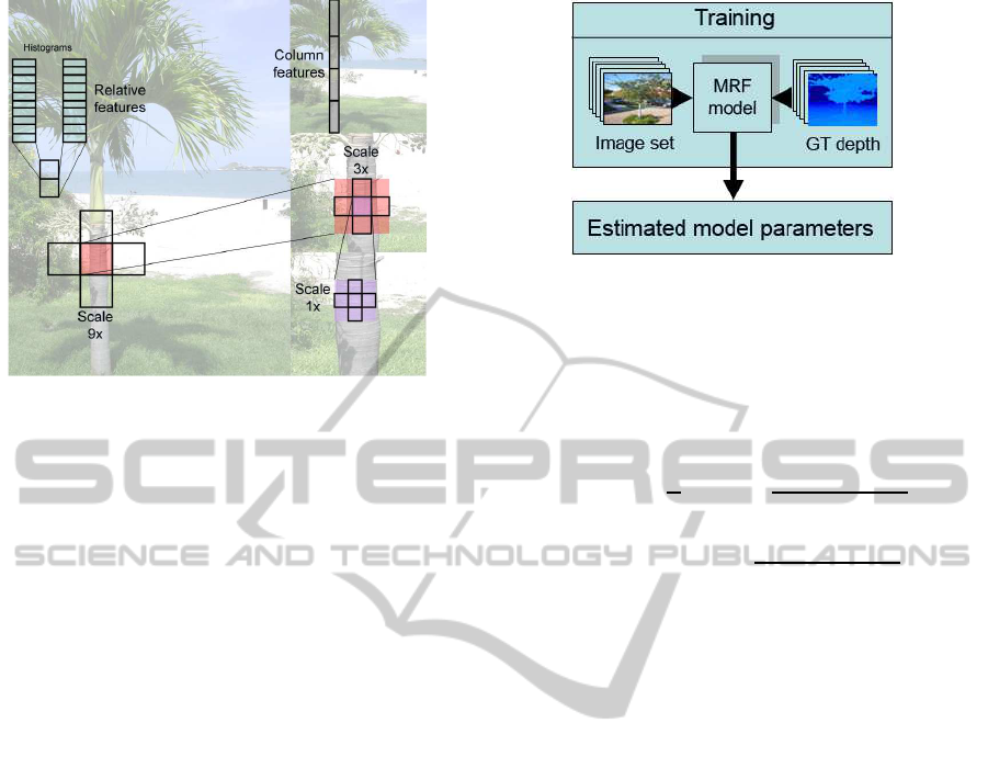
Figure 2: Selecting absolute and relative depth features in
three scales.
of local properties chosen for feature vectors are tex-
ture variation, texture gradients and haze. Texture can
be inferred from the intensity information by applying
Laws’ masks (Saxena et al., 2007). Haze information
can be extracted from the color channels by averag-
ing filter and finally, edge detector masks in different
orientations provide the texture gradient from inten-
sity image. Therefore, we can make the initial fea-
ture vectors by finding the sum absolute energy and
sum squared energy from the response of a patch and
its four neighboring patches to 9 Laws’ masks, color
channels and six gradient masks in three scales (Sax-
ena et al., 2005). In addition, the summary features
of the column which the patch lies in are added to
the feature vector. In this way for a selected patch
the feature vector can cover the relationship between
neighbors and very far neighbors. Moreover, in or-
der for finding the relative depth between neighboring
patches, a histogram of each of the filter outputs for a
patch is calculated. These features are used to show
how depths at different locations are related. Hence,
the differences between the histograms of the neigh-
boring patches can be used for relative depth estima-
tion.
5 MRF AND DEPTH MAP
RECOVERY
As discussed before, depth of a particular patch de-
pends on both features of the patch and depth of the
neighbors at different scales. In order to model this
dependency, MRF is used (Saxena et al., 2008).
Assume for each of three scales s = 1, 2,3 we define:
d
i
(s+ 1) = (1/5)
∑
d
j
(s), (1)
Figure 3: Training process.
where j ∈ N
s
(i) ∪
i
and N
s
(i) are the four neighbors
of the patch i at scale s. This definition indicates that
depth at higher scales is the average of depth at lower
scales. Therefore, the jointly Gaussian MRF model
for depth will be defined as:
P(d|X;θ,σ) =
1
Z
exp(−
M
∑
i=1
(d
i
(1) − x
T
i
θ
r
)
2
2σ
2
1rs
−
3
∑
s=1
M
∑
i=1
∑
j∈N
s
(i)
((d
i
(s) − d
j
(s))
2
2σ
2
2rs
)
(2)
Here, x
i
is the absolute depth feature vector for
patch i, M is the total number of patches, Z is the nor-
malization constant and σ and θ are the model param-
eters. Since for a horizontally mounted camera each
row in the image has a different statistical properties,
in reality different parameters for different rows can
be considered (Saxena et al., 2005). In the next step
a set of images and the corresponding depth maps are
used as training data. Hence, the parameters of the
system will be estimated by maximizing the condi-
tional likelihood of the training data. After the learn-
ing step, for a given set of test images we can find the
depth maps by maximizing the Eq. 2 in terms of d.
The estimated depth map for a single image is a key
point in our 3D visualization.
6 DEPTH NORMALIZATION AND
PIXEL LEVEL TRANSLATION
Stereoscopy or 3D imaging is the enhancement of
conveying the illusion of depth in photos or videos.
This effect can be presented by transmission of
slightly different image to each eye. In stereoscopic
visualization different algorithms have been devel-
oped and most of them are very empirical. One com-
mon and low cost group of stereoscopic methods are
color anaglyphs. In this method, which is known for
many years, users wear special glasses with two dif-
ferent left and right colors, each for filtering the corre-
3D VISUALIZATION OF SINGLE IMAGES USING PATCH LEVEL DEPTH
63
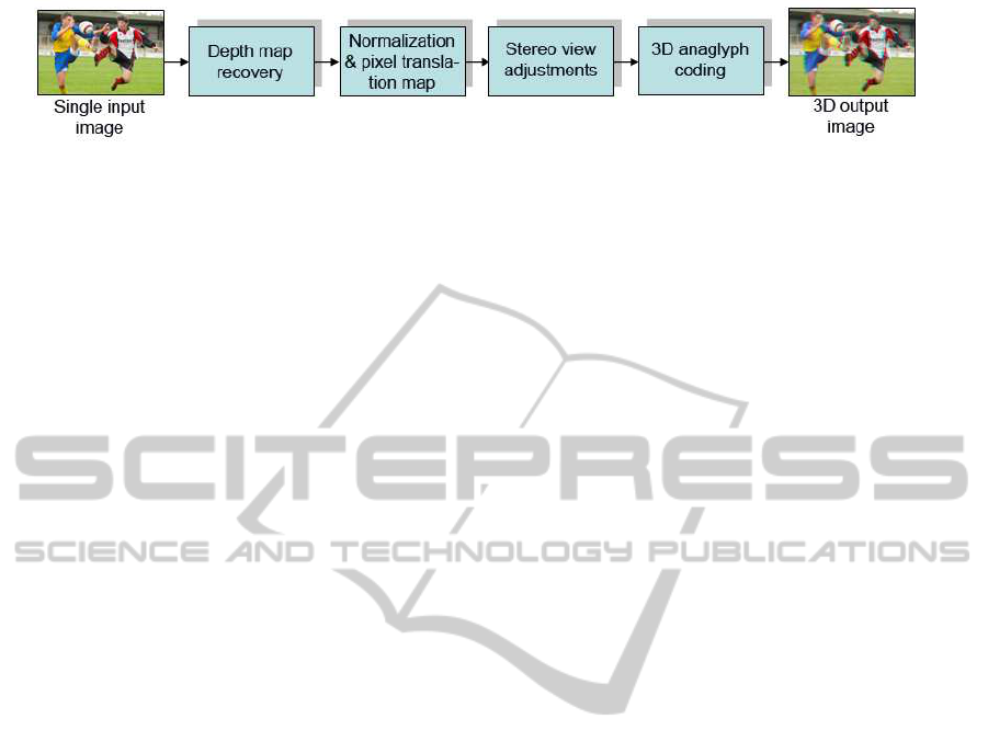
Figure 4: System Description.
sponding layer from the stereoscopic image or video.
The difference in perceived images from each eye is
the source of depth perception and 3D illusion. The
main principle behind the setup of stereo cameras is
to capture stereo views of a scene with a slight trans-
lation between two camera lenses (Jones et al., 2001;
Holliman, 2004). If we consider the captured images
by a stereo camera, it is obvious that the projected
points of the real scene on the image planes for closer
objects are bigger than the farther objects. In other
words, the distances between selected points of a real
scene in camera views become smaller when we move
from foreground to background. This is a key point
for adjustment of the stereo views from a single im-
age and the corresponding depth map. Therefore, in
order to make stereo views, we keep one channel fixed
and for the other channel we horizontally translate all
pixels according to their corresponding depths. Big-
ger translation will be allocated to lower depth pix-
els and smaller translation will be applied to higher
depths. Therefore, we use this inverse relation of the
depth and stereoscopic translation to map the normal-
ized pixel translation values to the interval [0-20].
7 ANAGLYPH 3D CODING
Up to this level, we could geometrically provide dif-
ferent views for left and right eyes. In order for
left eye signal to be different from right eye the
absorption curve has to be different. Furthermore,
due to the parallax in stereoscopic image pair it re-
quires at some points the luminance of one channel
be greater than the other and vice-versa (Tran, 2005).
Hence the absorption curves should satisfy the non-
overlapping bands and luminance condition. Based
on the above discussion, we implemented two dif-
ferent color anaglyphs known as red-cyan and color
code (amber-blue). The absorption curve for red-
cyan are in the range of [600-700nm] for left and
[400-600nm] for right filters. Similarly, for amber-
blue channels we have [500-700nm] for left and [400-
500nm] for right eyes (Tran, 2005). In the implemen-
tation the so-called optimized red-cyan anaglyph sug-
gested by Peter Wimmer (Wimmer, 2005) is used. As
it is shown in Eq. 3 optimized anaglyph discards the
red component of the original image and replaces that
with the red channel derived from the weighted green
and blue components. The cyan channel is directly
made of green and blue components. The improved
method with gamma correction is suggested in (Mcal-
lister et al., 2010)
r
a
g
a
b
a
=
0 0.7 0.3
0 0 0
0 0 0
∗
r
l
g
l
b
l
+
0 0 0
0 1 0
0 0 1
∗
r
r
g
r
b
r
(3)
The idea behind color code algorithm is that if one
eye perceives a view which is in color and the other
eye sees the view in monochrome, most likely the
fusion between these two channels contains the full
color range perception. Therefore, the amber color
allows most of the colors to go through the channel
and dark blue provides the monochrome image for the
other eye. Eq. 4 indicates the weights for color code
channels (Tran, 2005).
r
a
g
a
b
a
=
1 0 0
0 1 0
0 0 0
∗
r
l
g
l
b
l
+
0 0 0
0 0 0
0.11 0.22 0.67
∗
r
r
g
r
b
r
(4)
8 EXPERIMENTAL RESULTS
Fig. 4 shows the typical operation of our algorithm in
four main stages. Our trained system receives a sin-
gle monocular image as input. The algorithm recov-
ers the depth map from the input. Next, it normalizes
the depth map values and converts that to the pixel
translation values. Afterwards, it adjusts the transla-
tion for stereoscopic views and codes the channels for
color anaglyphs. Finally, the stereoscopic 3D image
will be merged and cropped for visualization. Ac-
cording to the analyzed error of the depth recovery
measured by (Saxena et al., 2005), the algorithm esti-
mates the depth maps with the average error of 0.132
order of the magnitude. It predicts the relative depths
quite well, but makes more errors in absolute depth
estimation. Since we normalize and map the depth to
pixel translation in our desired interval, we only con-
sider the relative depth of the patches and the absolute
SIGMAP 2011 - International Conference on Signal Processing and Multimedia Applications
64
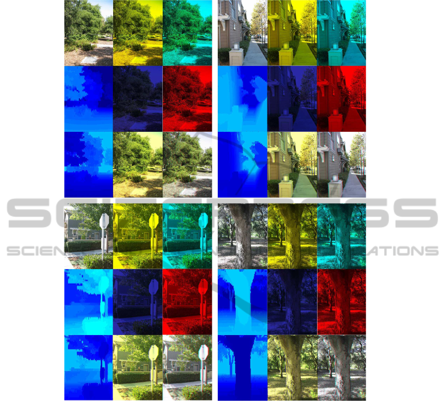
Figure 5: Result of the system on sample images. First columns: Original test image, recovered depth, normalized shift values
for 3D coding. Second columns: amber layer, blue layer, color code amber-blue 3D. Third columns: cyan layer, red layer,
cyan-red anaglyph 3D.
depth is not important for us. The satisfying final out-
put can also prove that.
Table.1 shows the calculated average processing time
for single images of different sizes. Experiments are
conducted in MATLAB 7.5.0 on a 2.9Ghz desktop
computer. Over 90% of the processing time is allo-
cated to depth recovery from monocular image and
the rest for 3D adjustments and anaglyph rendering.
The sample input images are selected from the col-
lection used by (Saxena et al., 2005). Rendering part
is performed for both red-cyan and amber-blue color
code anaglyphs (see Fig.5).
9 CONCLUSIONS
In this work we introduced a system for 2D to 3D
photo conversion and visualization using a single
monocular camera. Robustness, simplicity and effi-
ciency are the main advantages of the presented ap-
proach. This system helps users convert their 2D
photos into 3D regardless of having special expen-
sive capturing devices or 3D displays. In our method
patch level depth recovery and pixel level transla-
tion result in a high resolution 3D output. This ap-
proach provides a realistic depth perception and 3D
illusion for viewers. Other available systems which
convert single images to anaglyphs suffer from un-
3D VISUALIZATION OF SINGLE IMAGES USING PATCH LEVEL DEPTH
65

realistic visualization, distorted regions, unbalanced
foreground/backgroundor low resolution output. The
future work will be focused on the optimization and
enhancement of the current system in 2D to 3D video
conversion.
Table 1: Average processing time for different image sizes.
Image size Processing time/Sec.
360x440 82.12
640x480 141.38
1024x768 208.52
ACKNOWLEDGEMENTS
Special thanks to our colleagues from Digital Media
Lab., Ume˚a University for their helpful suggestions
and comments.
REFERENCES
Chaudhuri, S., R. A. (1999). Depth from defocus: A real
aperture imaging approach. In ISBN: 0387986359.
Springer.
Das, S. and Ahuja, N. (1995). Performance analysis of
stereo, vergence, and focus as depth cues for active
vision. In PAMI.
Dubois, E. (2001). A projection method to generate
anaglyph stereo images. In Proc. IEEE Int. Conf.
Acoustics Speech Signal Processing. IEEE Computer
Society Press.
Forsyth, D. and Ponce, J. (2003). In Computer Vision: A
Modern Approach. Prentice Hall.
Hartley, R. and Zisserman, A. (2003). In Multiple View Ge-
ometry in Computer Vision.
Holliman, N. (2004). Mapping perceived depth to regions
of interest in stereoscopic images. In Proc. SPIE Vol.
5291, Stereoscopic Displays and Virtual Reality Sys-
tems XI.
Jones, G., Lee, D., Holliman, N., and Ezra, D. (2001).
Controlling perceived depth in stereoscopic images.
In Stereoscopic Displays and Virtual Reality Systems
VIII. 200–1.
Lindeberg, T. and Garding, J. (1993). Shape from texture
from a multi-scale perspective. In Computer Vision,
1993. Proceedings., Fourth International Conference
on.
Maki, A., Watanabe, M., and Wiles, C. (2002). Geotensity:
Combining motion and lighting for 3d surface recon-
struction. In IJCV. Springer.
Malik, J. and Perona, P. (1990). Preattentive texture dis-
crimination with early vision mechanisms. In Journal
of the Optical Society of America.
Malik, J. and Rosenholtz, R. (1997). Computing local sur-
face orientation and shape from texture forcurved sur-
faces. In IJCV. Kluwer Academic Publishers.
Mcallister, D., Zhou, Y., and Sullivan, S. (2010). Methods
for computing color anaglyphs.
Michels, J., Saxena, A., and Y. Ng, A. (2005). High speed
obstacle avoidance using monocular vision and rein-
forcement learning. In In ICML.
Nagai, T., Naruse, T., Ikehara, M., and Kurematsu, A.
(2002). Hmm-based surface reconstruction from sin-
gle images. In Image Processing. 2002. Proceedings.
2002 International Conference on.
Quartulli, M. and Datcu, M. (2001). Bayesian model based
city reconstruction from high resolution isar data. In
IEEE/ISPRS joint workshop remote sensing and data
fusion over urban areas.
Saxena, A., Chung, S., and Ng, A. (2005). Learning depth
from single monocular images. In NIPS 18. MIT
Press.
Saxena, A., Sun, M., and Ng, A. (2007). Learning 3-d scene
structure from a single still image. In ICCV workshop
on 3D Representation for Recognition.
Saxena, A., Sun, M., and Ng, A. (2008). Make3d: Learning
3d scene structure from a single still image. In Pat-
tern Analysis and Machine Intelligence, IEEE Trans-
actions on.
Scharstein, D. and Szeliski, R. (2002). A taxonomy and
evaluation of dense two-frame stereo correspondence
algorithms. In IJCV.
Sinha, P., Blthoff, I., and Blthoff, H. (1998). Top-down in-
fluences on stereoscopic depth-perception. In Nature
Neuroscience, 1:254257.
Tran, V. (2005). New methods for rendering of anaglyph
stereoscopic images on crt displays and photo-quality
ink-jet printers. In Ottawa-Carleton Institute for Elec-
trical and Computer Engineering.
Wimmer, P. (2005). Anaglyph methods comparison. In
http://www.3dtv.at/Knowhow/.
Wu, B., Ooi, T., and He, Z. (2004). Perceiving distance ac-
curately by a directional process of integrating ground
information. In Letters to Nature, 428:7377.
Zhang, R., Tsai, P., Cryer, J., and Shah, M. (1999). Shape-
from-shading: a survey. In Pattern Analysis and Ma-
chine Intelligence, IEEE Transactions on.
SIGMAP 2011 - International Conference on Signal Processing and Multimedia Applications
66
