
VERIFICATION OF THE CONSISTENCY BETWEEN USE CASE
AND ACTIVITY DIAGRAMS
A Step Towards Validation of User Requirements
Sana Oueslati Ben Amor, Mouez Ali and Faïez Gargouri
MIRACL Laboratory, ISIMS, University of Sfax, Sfax, Tunisia
Keywords: UML, Use case, Activity, Validation, User requirement.
Abstract: The requirements elicitation is a step between the user and developers has to be precise and formal. This
step requires understanding the requirements to be covered by the system and to express and formalize these
requirements. For structuring, documenting and analysing user requirements, UML use case diagram
illustrates all functional requirements. In an advanced step, all functionalities of a system can be represented
and detailed by a set of activity diagrams. In our work, the requirement validation is to check that all
requirements are covered by these functionalities. In this paper, we present a validation requirement
approach of UML models based on a comparison of UML use case (requirement) and activity diagrams
(functionality). This comparison ensures that the use case model and activities model are consistent. It is
based on a set of rules. Furthermore, we give an overview of UML-Validation tool which automates the use
of these rules.
1 INTRODUCTION
The requirements specification is a critical step in
developing any new project. The project's success
begins with a clear definition of the requirements of
future users. It is used to apply the techniques to
monitor, validate and manage project requirements
(Nuseibeh, 2000).
As a part of the requirement specification, the
requirement validation is a critical step that must be
precise and formal. This step checks that all
requirements are covered by the system
functionalities. To structure, document and analyze
user requirements, UML (Unified Modeling
Language) enjoys popularity within the academic
and industrial communities. Indeed, the UML
language allows structuring the functional
requirement by a use case diagram. In a future
development step, this diagram can be specified and
refined by others UML diagrams like activity
diagrams. The diversity of UML diagrams and the
development process can easily lead a developer to
define diagram inconsistency.
UML use cases can structure the user
requirements and objectives of a corresponding
system. In fact, use cases are informal and described
in natural language.
Generally, system validation includes all the
techniques to evaluate the system developed against
the requirement of users. For UML diagrams, the
validation method of user requirements ensures that
all UML diagrams, developped by a designer
express correctly the user requirements.
Our proposal extends the approach proposed by
(Ali, 2006). This approach makes explicit the
dependency relationships between UML diagrams.
Our approach ensures a form of consistency between
the diagram use case and activity diagram. Indeed,
we identify and formalize a set of rules of
correspondence between the use case diagram and
activity diagram. Then, we propose a prototype
validation of user requirements.
This paper is organized as follows; in section 2,
we detail our validation requirement approach of
UML models. In section 3, we explain our working
example. Finally, the conclusion summarizes the
presented work and give outlines of future works.
2 OUR APPROACH
Let’s recall that validation activity includes all the
techniques to evaluate the system developed against
the user requirements. For UML models, the
396
Oueslati Ben Amor S., Ali M. and Gargouri F..
VERIFICATION OF THE CONSISTENCY BETWEEN USE CASE AND ACTIVITY DIAGRAMS - A Step Towards Validation of User Requirements.
DOI: 10.5220/0003505503960399
In Proceedings of the 13th International Conference on Enterprise Information Systems (ICEIS-2011), pages 396-399
ISBN: 978-989-8425-55-3
Copyright
c
2011 SCITEPRESS (Science and Technology Publications, Lda.)
validation activity permits to validate the user
requirement model compared to the analysis model.
In our work, UML requirements are represented by
the use case diagram and we supposed that the
system functionalities are represented by the activity
diagram.
The problem consists in validating user
requirements expressed by use cases compared to
the activity diagram.
Our work is a partial validation. We choose to
validate the activity diagram against user
requirements because the activity diagrams permit to
describe a system feature illustrated by a use case.
Given the dependence between these two diagrams,
it is necessary to ensure the consistency between the
use case diagram and the activity diagram.
2.1 An Overview
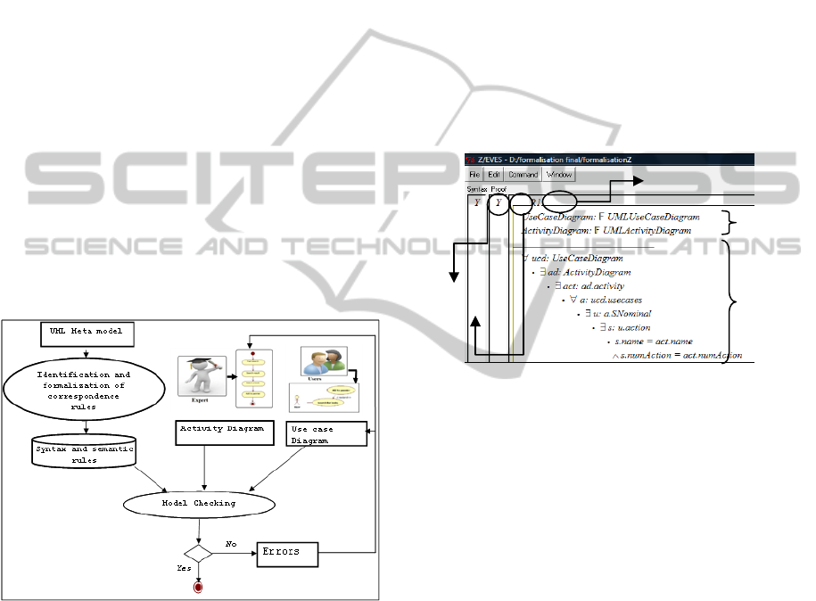
Figure 1 gives an overview of our approach of UML
requirement validation. First, we identified a set of
correspondence rules between the use case diagram
and activity diagram based on UML meta-model.
Then, we formalized these rules by the formal
language Z (Spivey, 1992).
Figure 1: An overview of the approach of UML
Requirement Validation.
Our contribution includes:
− Formalization of use case and activity diagrams ,
− Identification and formalization of the inter-
diagrams rules ($ section 2.2),
Next, we present a CASE tool to experiment our
checking rules.
In the next session of the research, we propose
the different syntactic and semantic checking rules.
2.2 Syntactic and Semantic Checking
Rules
In this work, we also identify and formalize ten
rules, ensuring consistency between the elements of
a use case diagram and activity diagram. These rules
are generic and independent from the area studied.
We present only the main important rules. In this
work, we assume that:
Rule1.
Each use case U
c,
is described by at least an
activity diagram. This diagram must be composed at
least by an initial node, a final node and an activity
node.
The formalization of this rule is presented in
Figure 2. This rule checks that the use cases
“ucd.usecases” and activity diagrams “ad” have the
same name (s.name= act.name)
Figure 2: Formalization of Rule 1.
Rule 2. An alternative scenario AS (or errors
scenario ES) of a use case U
c
is represented by an
activity diagram
A
c
composed of at least one
decision node
«Decision Node» and a set of
activities connected by control flow or data.
Rule3. Each action a
i
taken by an actor in U
c,
is
represented by an activity Ac
i
. The pre-condition in
the use case Uc is represented by the guard
condition of a
i
.
Thus, the action’s order in use case must be
preserved by the activity’s order in activity diagram.
Rule 4.
The first action a
1
performed by an
actor is represented by the first activity Ac
1
in the
corresponding activity diagram. It must be linked
with the initial node
. a
1
and Ac
1
must have the same
signature.
Rule 5. The last action a
f
performed by the
system of the Nominal scenario Ns is represented by
the last activity ac
f
of the activity diagram
corresponding node connected with the final node
by a control flow. Thus, a
f
and ac
f
have the same
signature.
The variables
Rule 1
The predicate
Syntactic checking
Semantic checking
VERIFICATION OF THE CONSISTENCY BETWEEN USE CASE AND ACTIVITY DIAGRAMS - A Step Towards
Validation of User Requirements
397
Rule 6. All pre-conditions Pc
i
of a use case U
c
are represented by the condition for triggering the
first event of the corresponding activity diagram.
Rule 7. All post-conditions Pc
i
of a use case U
c
are represented by the condition of the flow between
the last activity ac
f
with the final node of activity
diagram
A
c
corresponding to use case U
c.
Rule 8. If there is a relationship « include »
between two use cases U
c1
and U
c2
,
then there exists
an activity diagram A
c
specifies the two use cases.
There is an action belonging to the list of actions
ac
1
, from which it is calling for measures to ac
2
.
These constraints are talking about the no
existence of the conceptual elements between the
two diagrams. The identification of significant
inconsistencies is missed. Moreover, it remains to
refine certain rules identified. Indeed, we have
formalized and implemented only the first 7 rules.
In the next section, we present our working
example of the online library application.
3 WORKING EXAMPLE
We present a case study of the online library
application. This application allows users to search
books by subject, author, keyword, etc. It permits to
complete a shopping cart (Pascal, 2003).
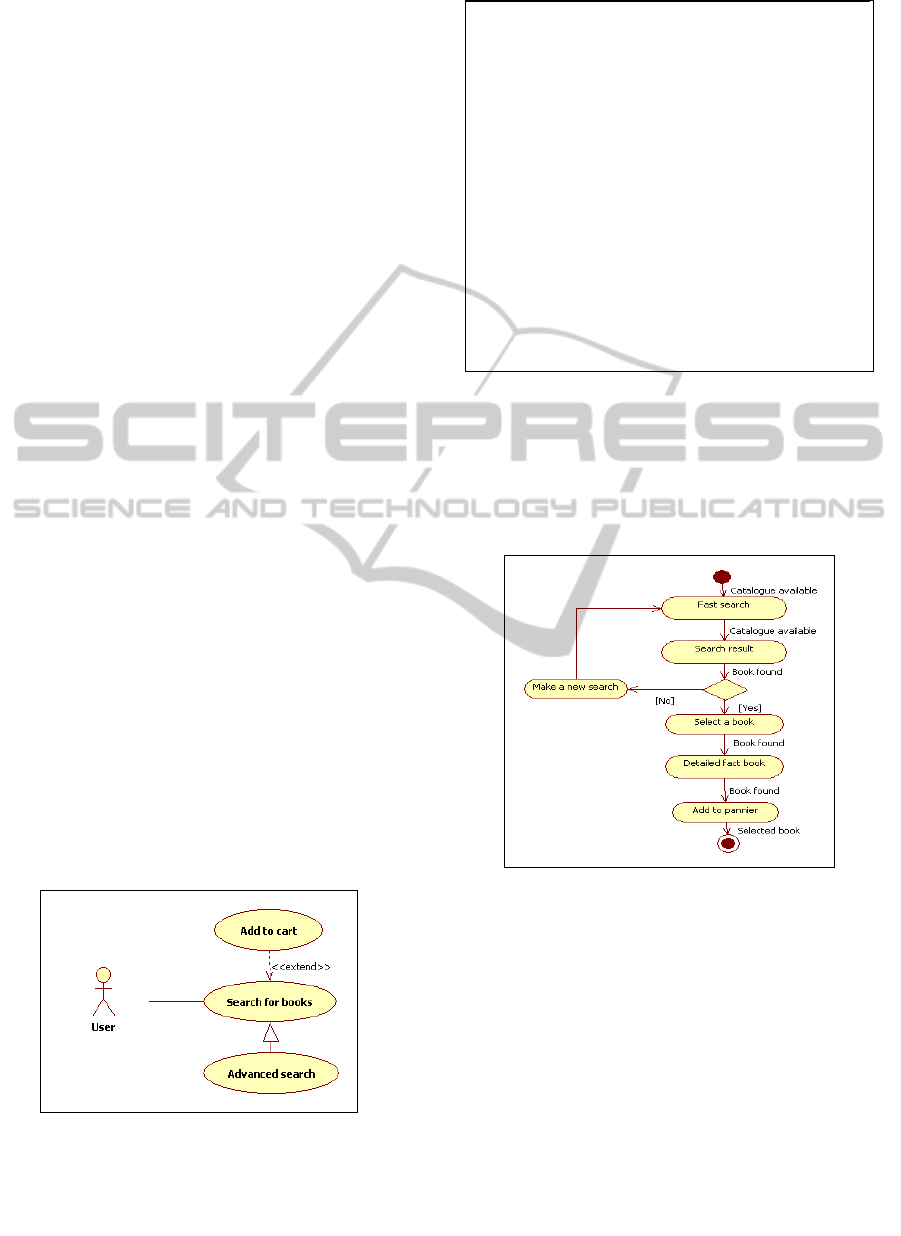
3.1 Use Case Diagram
The purchase process of books is described by a use
case diagram illustrated by three use cases. We will
detail the use case "Search for books" of the online
library case study.
Figure 3 shows a part of the use case diagram of
an online library.
Figure 3: A part of use case diagram of online library
(Pascal, 2003).
The documentation of the use case "Search for
books" is presented in the figure 4.
Use case <Search for books>
Acteurs: <User>
Pre-conditions: <Catalogue available>
[Extension point : <Selected book>]
/* Basic Flow */
SN
Start
-<1> [<Catalogue available>] <User> <Fast search
>
-<2>[<Catalogue available>] <System> <Search
result>
-<3> [<Book found>] <System> <Select a book>
-<4> [<Book found>] <System> <Detailed fact book>
-<5> [<Book found>] <User> <Add to pannier>
End
/* Alternative Scenarios */
SA
Start
<Book not found, start 2>
- <3 > [<Book not found >] <User> <Make a new
search>
Restart 1
End
Use
case
Figure 4: Documentation relating to the use case "Search
for books".
3.2 Purchase Activity Diagram
The use case "Search for books" is specified by an
activity diagram (Figure 5).
Figure 5: Activity diagram of the book search process
(Pascal, 2003).
3.3 Checking the Rules
The test of the important rules is given as follows:
Rule 1: This rule is satisfied because the “Search
for books” use case has a “Search for books”
activity diagram.
Rule2. This rule is satisfied by these two diagrams
($ sections 3.1 & 3.2) because there is an alternative
flow “Book not found” in the textual description of
the use case “Search for books” and only one
decision node in the correspond activity diagram
(Figure 5). Also, the “Make a new search” action for
ICEIS 2011 - 13th International Conference on Enterprise Information Systems
398

the use case “Search for books” has a “Make a new
search” activity.
Rule3. This rule is satisfied by these two diagrams
because any action taken by an actor in the textual
description of the use case “Search for books” is
represented by an activity in the corresponding
activity diagram. In fact, the “Fast search”, “Search
result”, “Select a book”, “Detailed fact book”,
“Add to pannier” actions have the “Fast search”,
“Search result”, “Select a book”, “Detailed fact
book”, “Add to pannier” activities.
Rule4.
This rule is satisfied by these two diagrams
because the first action “Fast search” performed by
an actor “User” is represented by the first activity
“Fast search” linked with the initial node
of the
corresponding activity diagram.
Rule5. This rule is satisfied by these two diagrams
because the last action “Add to pannier” performed
by the system of the nominal scenario is represented
by the last activity “Add to pannier” of the activity
diagram corresponding node connected with the
final node by a control flow.
4 CONCLUSIONS AND FUTURE
WORK
In this paper, we have proposed a formal approach
for validating UML requirements. This approach is
based on structured use cases. It ensures that a use
case diagram and the activity diagram are
consistent. We have identified and formalized a set
of syntactic and semantic correspondence rules
between these diagrams. The approach is tested by a
working example. To implement these rules, we
developed a tool which can check these rules and
return a summary of errors.
In the future work, we will look for improving
our tool. Certainly, the approach and the developed
tool require more improvement. Indeed, it remains
to refine certain identified rules. Moreover, the
prototype UML-Validation requires improved
graphical interface. Finally, we propose to integrate
our proposal in the MDA (Model Driven
Architecture) approach.
REFERENCES
Ali M., Ben-Abdallah H., Gargouri F., 2006. “ Validation
requirements in UML 2.0 Models", Proceedings of the
24th International Congress of Computer
IFORSID’06, pages, Hammamet Tunisia.
Nuseibeh B., Easterbrook S., 2000. “Requirements
Engineering: A Roadmap", Proceedings of
International Conference on Software Engineering
(ICSE-2000), Limerick, Ireland, ACM Press.
Pascal R., 2003. “UML Modelling an e-commerce site".
Eyrolles.
Spivey J., 1992. “The Z Notation": A Reference Manual,
Prentice Hall, 2nd edition.
VERIFICATION OF THE CONSISTENCY BETWEEN USE CASE AND ACTIVITY DIAGRAMS - A Step Towards
Validation of User Requirements
399
