
DOMAIN-SPECIFIC MODELLING APPLIED TO INTEGRATION
OF SMART SENSORS INTO AN INFORMATION SYSTEM
Jean-Philippe Schneider, Jo¨el Champeau, Dominique Kerjean
ENSTA Bretagne Pˆole STIC, 2 rue Franois Verny, 29200 Brest, France
Oussama Zein
Computer Science Department, Arts, Sciences & Technology University in Lebanon (AUL)
Beirut Campus-Commodore Street, Hamra, Lebanon
Keywords:
Smart sensor metamodel, Software architecture, Embedded real-time software, Code generation.
Abstract:
(Kopetz, 1997) stated that a trend in the sensor technology is the development of intelligent sensors also called
smart sensors. The development of such sensors do not only rely on the hardware development but also on
the software. The later should so meet the requirements on low costs and of quality. This paper presents
our approach to model the software of a smart sensor and to generate the code for the embedded real-time
application. It will also describe how the use of a domain-specific modelling methodology enabled us to
achieve a high level of modularity which will permit to save costs and development time.
1 INTRODUCTION
(European Commission, 2008) states that the ma-
rine environment should be preserved. It enforces a
new legislation on the state members of the European
Union to protect their marine waters by developing
a preservation strategy. This strategy should include
surveillance aspects. According to (Favali and Be-
ranzoli, 2006) only long term study provided by a
seafloor observatory can fulfil the needs expressed by
the European Commission. As a matter of fact a long
term study provides data on occurring events, eases
the correlation of multiple kinds of data for a particu-
lar area and enables studies on different time scales. It
also meets the requirements ofthe EuropeanCommis-
sion for coastal area. (Spencer et al., 2004) stresses
that a technology called smart sensors brings the abil-
ity to tackle the issue of scalability. That is why the
use of smart sensors in a seafloor observatory can be
interesting.
The different data acquired by the sensors must
be sent to a ground station to be analysed. So the sen-
sors are linked to an information system. However the
sensing domain and the information system domain
are very different in their basic requirements. So the
design of a sensor does not take into account the nee-
ds of the information system. Both a conceptual and
a functional gap exists between the sensors and their
associated information system. In order to fill this
gap a possible approach is to use Model Driven En-
gineering (MDE). The design phase of the sensor is
left unchanged but through a code generation process
it is possible to integrate easily the sensor into the
information system. Our approach enables to gener-
ate both the functional code of a sensor and the code
that links the sensor to its information system with the
same model.
Section 2 delves into the issue of the use of so
called smart sensors in the field of seafloor observato-
ries and how it is possible to model them. Then sec-
tion 3 dwells on the proposed architecture for the real-
time embedded software of the smart sensors. After
that section 4 expands on the code generation strat-
egy. Finally section 5 concludes on our approach for
modelling and generating operating embedded code
for smart sensors and provides clues on the next steps
of our work.
253
Schneider J., Champeau J., Kerjean D. and Zein O..
DOMAIN-SPECIFIC MODELLING APPLIED TO INTEGRATION OF SMART SENSORS INTO AN INFORMATION SYSTEM.
DOI: 10.5220/0003500602530259
In Proceedings of the 13th International Conference on Enterprise Information Systems (ICEIS-2011), pages 253-259
ISBN: 978-989-8425-55-3
Copyright
c
2011 SCITEPRESS (Science and Technology Publications, Lda.)

2 SMART SENSORS FOR SEA
FLOOR OBSERVATORIES
This section intends to provide an overview of smart
sensing and of the specific needs for seafloor obser-
vatories. Then we would like to expand on the Smart
Sensor metamodel introduced in (Zein et al., 2009).
2.1 Definition
(Spencer et al., 2004) introduces the main concepts
which enable to differentiate smart sensors. Their
main characteristics are the presence of an embed-
ded Central Processing Unit, their small size, their use
of wireless communications and their promise of be-
ing low cost. The use of a microprocessor enables
to do digital processing, to ease self-diagnostics, self-
adaptation or self-identification by the use of interfac-
ing functions and to do some calculations. In (Brooks,
1999) Brooks describes the basic functions a smart
sensor must provide. Among them are bi-directional
command and data transmission, user-defined algo-
rithms, internal self-verification/analysis and com-
pensation algorithms.
2.2 Specificities in the Context of
Seafloor Observatories
Seafloor observatories are an excellent proving
ground for the use of smart sensors in a stringent
environment. We are currently working on a cabled
coastal seafloor observatory network called MeDON
(Marine eData Observatory Network, 2011). The re-
quirements for the MeDON seafloor observatory net-
work are described in (MeDON, 2010).
Although the smart sensors are described to have
wireless communications with the rest of the world,
the specificities of the marine environment force to
use a cabled communication between the physical
sensor and a relay point that concentrates the data
coming from the different smart sensors. Even with
a cabled network we have to face some design chal-
lenges. The first challenge is to obtain a robust soft-
ware. The coastal environment may be considered as
hostile for the hardware which have to be designed to
resist to strong underwater current. It means also that
it will not be easy to replace a faulting component.
Along with the need of robustness comes the need
of remote logging. So the sensor network must have
the ability to provide full state information for the dif-
ferent sensors and more precisely their failure state
and the events causing them. It implies the need for
the software to have logging facilities both networked
and on-board. It also requires the different software
units to be capable of handling the occurring excep-
tions.
Besides due to the environmental conditions and
the low costs requirements the cabled links between
the sensors and the ground station will be made of
Ethernet links. However, we have to transfer high
quantities of raw data. So we are facing some chal-
lenges in the design of the data transmission facilities
which can lead to the definition of an internal transfer
protocol.
A last but not the least requirement on the sys-
tem is the need of modularity in the software part.
The smart sensors developed for the MeDON project
must have the ability to be connected to various hard-
ware sensors with various interface protocols. Due to
the low cost requirement it is not possible to design
a smart sensor for each physical sensor. The devel-
oped smart sensor infrastructure both hardware and
software must support the different physical sensor.
So we have to achieve a high level of modularity. We
also need to be able to create clean communication
means between the sensor vendors and the final user
of the smart sensors. A first step to fulfil this require-
ment is to use a modular design methodology such as
MDE.
2.3 A Metamodel for Smart Sensors
One of the approaches described in model driven en-
gineering is the use of domain specific languages
(DSLs) to cope with issues specific to a particular do-
main. In (Zein et al., 2009) Zein and al. introduced
a metamodel to define a DSL for the design of smart
sensors.
This metamodel describes the three main aspects
of a smart sensor, its interface with the environment,
its attributes and its behaviour. From a high level
point of view it can be seen as a regular UML ob-
ject with public and private attributes and methods
and which implements different interfaces. This co-
herence between the metamodel for smart sensors and
the object oriented design eases the system design of
the whole system in which the sensors will be in-
cluded.
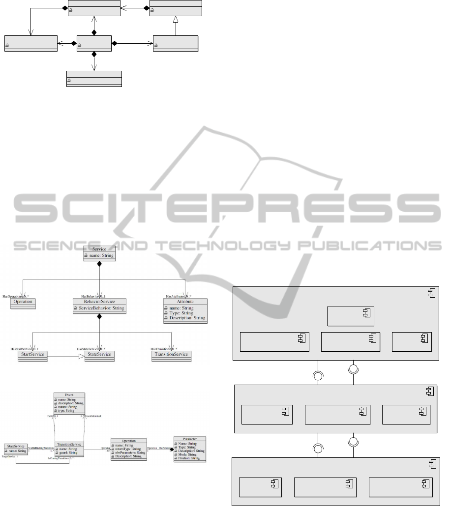
Figure 1 page 3 shows the description of the in-
ternal structure of a sensor. It may have two differ-
ent interfaces. The first one defines the sensor global
features that are available for the environment. The
second one is type specific. It determines all the fea-
tures that are associated to the type of sensor. Each of
these interface is linked to the global behaviour of the
sensor which determines the way the sensor interacts
with its environment. Among the static properties of a
sensor its latitude, longitude and depth can be found.
ICEIS 2011 - 13th International Conference on Enterprise Information Systems
254
Interface
InterfaceName: String
Sensor
Name: String
ProprieteStatique
StaticPropName: String
SensorInterface
InterfaceName: String
SensorType
TypeName: String
BehaviorSensor
BehaviorName: String
HasInterf ace 0..1
HasSensorInterface
0..1
HasBehavior
0..1
HasBehavior 1
HasProprieteStatique 0..1
HasSensorInterface
0..1
HasType
1
Figure 1: Description of the structure of a sensor in the
smart sensor metamodel.
Each interface is made of a set of services. A ser-
vice is the functional element of the sensor as it is de-
scribed in Figure 2 page 3. The behaviour of a service
is described as a finite state machine as shown in Fig-
ure 3 page 3. The transition are event triggered. Dur-
ing the transition the associated operation are called.
These operations are able to emit events. So the inter-
nal communication within the sensor is made of the
event based communication between the different ser-
vices.
Figure 2: Description of the services provided by the sensor.
Figure 3: Description of the behaviour of a service.
This metamodel enables to model the functioning
of a smart sensor at a high abstraction level. As this
description is platform independent it can be reuse for
the definition of other smart sensors. This is eased
by the fact that the metamodel makes a clear separa-
tion between the behavioural and the structural fea-
tures and between the type specific elements and the
global ones. HoweverPohjonen and Kelly pointed out
in (Pohjonen and Kelly, 2002) that the use of Domain-
Specific Modelling cannot only rely on the domain
metamodel. It must be linked with a well-defined ar-
chitecture of the targeted software and platform. The
use of the combination of metamodelling and soft-
ware architecture provides the separation of concerns
needed to easily integrate a smart sensor in a complex
information system. In order to complement Zein’s
work we suggest a platform independent software ar-
chitecture.
3 INTEGRATION IN THE
INFORMATION SYSTEM
3.1 Software Architecture
A smart sensor is made of two levels of services
which can be distinguished according to their level
of abstraction from the hardware part of the sensor.
This view of the composition of a smart sensor en-
ables to build a software architecture based on lay-
ers. According to (Krakowiak, 2009) it is a conve-
nient way to deal with multilevel application. Figure
4 page 3 shows the layered structure of the software
and the internal components of each layer.
HardwareLayer
LwIp
DriverSensor DriverStoring
ControlLayer
Network SensorControl Storing
ServiceLayer
MeasureResults DataAccess
Log
Config
Figure 4: Layered view of the software architecture.
The lowest layer deals with the hardware part of
the sensor. So it is made of the different drivers
needed to the functioning of the sensor. The mid-
dle layer which is called Control Layer is made of
the low level services of the smart sensor. They are
the control services of the smart sensor which pro-
vide the needed control and overview of the hardware
DOMAIN-SPECIFIC MODELLING APPLIED TO INTEGRATION OF SMART SENSORS INTO AN INFORMATION
SYSTEM
255

of the sensor. The highest layer which is called Ser-
vice Layer is made of the high level services. Those
services are defined by the user and provide the em-
bedded intelligence of the smart sensor. Each layer is
able to communicate with its neighbours through in-
terfaces. Table 1 page 5 describes the services which
are involved in the integration of the smart sensor in
the information system.
According to the description of the different ser-
vices we can distinguish two kind of integration into
the information system. The first one is a logical in-
tegration. The high level services and the SensorCon-
trol service provide their functions to the information
system. So the other elements of the information sys-
tem can logically access to their function. However
the physical way to access to those services is not de-
fined. It is the Network service which provide the
physical integration of the smart sensor into the in-
formation system infrastructure. It defines the way
to address the smart sensor in the information system
which also defines the way to access to the proposed
logical services.
3.2 Logical Integration
The first level of integration of a sensor into an infor-
mation system can be called logical integration. This
level consists in making a description of the sensor
available for the different actors in the information
system. As the description is an abstraction of the
actual sensor it can be considered as a logical view of
the sensor. Such a description can be obtain by the use
of metadata as stated in (Joshi, 2007). In the sensing
field a format for the metadata is the SensorML lan-
guage from the Open Geospatial Consortium (Open
Geospatial Consortium Inc., 2007). It enables to de-
scribe the data which are provided by the sensor. It
especially describes the measures which are done by
the sensor, their type and their format. So any applica-
tion in the information system is aware of the kind of
data provided by the sensor without being physically
linked to it.
3.3 Physical Integration
Through the logical integration the information sys-
tem is aware of the abilities of the smart sensor. But
it has no way to really access to those functionalities.
In order to make them available we decide to organise
the smart sensor according to the REST architecture
principles described in (Fielding, 2000). REST re-
lies on the use of the HTTP protocol. All the actions
of the sensor are commanded by HTTP packets. A
HTTP packet begins with the name of a method and a
targeted URL. The REST architecture only uses four
of the methods defined by HTTP:
• GET: retrieves the resource from the targeted
URL.
• POST: creates the resource at the targeted URL.
• PUT: updates the resource at the targeted URL.
• DELETE: removes the resource at the targeted
URL.
The HTTP packets are parsed. According to the re-
sults of the parsing predefined functions are called.
So the REST architecture provides a standardised way
for the stakeholders of the information system to com-
municate with the sensors. In our case a URL is a
service provided by the sensor. We derived the mean-
ing of the HTTP methods used in REST to fit to our
specific needs:
• GET: retrieves the value of the attributes of the
service.
• POST: starts a service.
• PUT: changes the value of the attributes of the ser-
vice.
• DELETE: stops a service.
The use of a REST infrastructure for the command
and control of the sensor provides a lightweight
mechanism which can be easily extended and reused
among the information system. The distinction be-
tween the logical and the physical integration of the
smart sensor in the information system provides the
needed flexibility in the information system. It en-
sures that any change in one integration mode will not
affect the other one which provide a more efficient
way to maintain the smart sensor in the information
system.
4 CODE GENERATION
4.1 Description of the Modelling
Method
The metamodel for smart sensors seems to be able to
handle different modelling levels. In order to test this
ability we have completely modelled a smart sensor
for an hydrophone.
The first step in the modelling of a smart sensor
is to define its global behaviour and its interfaces.
We choose to command the smart sensor using HTTP
commands as defined by REST. So the global be-
haviour describes the reaction of the sensor toward the
ICEIS 2011 - 13th International Conference on Enterprise Information Systems
256

Table 1: Relevant services for the integration in the information system.
Services Description
Network Enables to receive command
through the network and sends data
back.
SensorControl Performs the actual measure by
controlling the hardware sensor.
Config Enables the configuration of the
sensor. It includes among others
the frequency of acquisition and the
number of bits.
Log Enables to log the exceptions occur-
ring in the system.
DataAccess Enables to get the data stored within
a time interval or to flush the mem-
ory.
MeasureResults Enables to access to the last mea-
sure from the sensor.
arrival of a network message and its call of an imple-
mentation specific service which defines which high
level service should be triggered. The behaviour also
defines that the smart sensor is able to send data back
to the control station.
There are two interfaces. The global interface
which contains the Log, the NetworkManager, the
Dispatching, the DataAccess, the Storing and the
TimerStoring services. The SensorControl, the Con-
fig, the MeasureResults and the TimerMeasureResults
are defined in the type specific interface for SoundDe-
vice.
The different services have been mapped to the
concept of Service defined in the metamodel. The
high-level services distinguish themselves from the
low-level ones as they are purely functional. So they
do not need to have an associated behaviour. When
needed the behaviour of a service has been described
as a state machine. Figure 5 page 5 depicts the be-
haviour of the SensorControl service as a finite state
machine.
IdleMeasure
tmFreqSensor/doMeasure()
Figure 5: Description of the behaviour of the SensorControl
service.
The state is defined a a StartService state which
is a concept defined in the metamodel. Table 2 page
6 describes how the depicted transition is modelled
according to the smart sensor metamodel.
The high level services are only described as a set
of Attributes and of Operations. The functional code
associated with an operation is added in C language
in the description field of the Operation.
4.2 Projection on the Platform
The previously defined model can now be used to
generate code for the embedded target. The target
is made of a Luminary LM3S9B96 central process-
ing unit with an already ROM-loaded operating sys-
tem. The operating system is SafeRTOS (High In-
tegrity Systems, 2011). This operating system defines
a dynamical preemptivescheduler. The different tasks
can have the same priority. The interprocess commu-
nication mechanism is only made of message queues.
There is also no mutual exclusion mechanism. These
kind of facilities should be emulated by the use of
message queues.
The low-level services are translated into tasks.
Each task will have a message queue associated to it.
Their behaviour is described with switch-case state-
ments. The wait for the reception of an event is im-
plemented as the wait for the reception of a message
in the message queue associated to the task. However
SafeRTOS does not provide a blocking wait mech-
anism that is why a test should be implemented in
order to ensure that the expected event has been re-
ceived. Table 3 page 6 defines the rules associated to
the implementation of the state machine of the low-
level services.
The high-level services are translated into C struc-
tures. Those structures are made of fields representing
the attributes of the service and of pointer of functions
that describes the operation associated to the service.
DOMAIN-SPECIFIC MODELLING APPLIED TO INTEGRATION OF SMART SENSORS INTO AN INFORMATION
SYSTEM
257

Table 2: Description of a transition of a finite state machine according to the smart sensor metamodel.
Metamodel concept Value
Name IdleMeasureTmFreqTransition
event tmFreqSensor
eventSubmitted
outServiceState IdleMeasure
inServiceState IdleMeasure
Operation doMeasure
Table 3: Implementation rules of a finite state machine.
Metamodel concept Translation
BehaviorService switch-case statement
StateService Integer value
TransitionService wait operation
guard if statement
event if statement
We also defined rules to create the SensorML descrip-
tion of the smart sensor. This description can be em-
bedded in the software as a constant.
We have obtained a mapping between the con-
cepts defined in the SMS metamodel and the code
that can be written in C language or the SensorML de-
scription of the sensor. This mapping defines the rules
used to automatically generate code from a model
compliant to the smart sensor metamodel into the em-
bedded software for the physical smart sensor. We
used the Kermeta workbench (Triskell team, 2011) in
order to implement the code generation.
4.3 Results
As we may have two different platform in the near fu-
ture we were forced to separate the architectural fea-
tures of the system and its platform features. A first
transformation is obtained by the mapping between
the metamodel concepts and the concepts defined in
the proposed architecture. A second one is specific to
the code generation. These process enables to do fine
tuning of the model obtained after the first transfor-
mation in order to be compliant with high constrain-
ing requirements. The second step of the process en-
hances the reusability of the model as the platform
specific implementation details are contained within
the code generator and not in the architecture.
The use of the smart sensor metamodel enables to
obtain a high level description of a smart sensor. It ef-
ficiently describes its structural and behavioural fea-
tures. This includes the description of the interaction
with the environment but also the internal exchanges
of information. As a consequence it enables to obtain
a well defined breakdown of a smart sensor. It also
helps in defining the different interfaces of the smart
sensor both external and internal. However it lacks of
facilities to describe the operational behaviour from a
domain point of view.
The use of a defined architecture enabled us to ob-
tain a generated code which corresponds to our basic
needs. Besides we have obtained a clearer separation
between concerns in the sensor domain and concerns
in the real-time systems domain. This architecture is
described using a general modelling language.
We have defined a methodology which uses a do-
main specific modelling languages and a general pur-
pose language in order to be able to generate code.
Each modelling language compensate for the lack of
expressiveness of the other one. The domain spe-
cific language enables to model the system according
to the domain requirements independently of the fi-
nal implementation. The general purpose modelling
language includes the domain specific definition of
the system and adds the different implementation spe-
cific mechanisms. As a result the generated code ful-
fils the domain needs and the real-time requirements.
We are also able to analyse the sensor in such a way
the integration process in the information system is
eased. The sensor can interoperate physically through
a HTTP server which can be automatically generated.
The REST architecture provides the logical integra-
tion of the sensor. The logical definition of the smart
sensor can be easily embedded in the generated code.
5 CONCLUSIONS
The use of domain specific modelling enables us to
develop quickly the software of a complex smart sen-
ICEIS 2011 - 13th International Conference on Enterprise Information Systems
258

sor. As we were able to identify quickly the needs for
real-time software mechanism and to separate them
from the design of the sensing part of the smart sen-
sor we made also gain in design time. The designer
only has to focus on the definition of the smart sen-
sor the rest would be generated automatically. We
have also made significant gain during the definition
of the generator as the target elements of the map-
ping between the high level model of the smart sen-
sor and the architecture are well described. It implies
that a smart sensor can be easily and more quickly de-
ployed according to its definition. The smart sensor is
also easier to maintain. Any change of its definition
or of the architecture only requires a regeneration of
the code which could then be implanted again in the
smart sensor. The latency between the notification of
the change and the deployment of the modified smart
sensor is reduced. This is a great benefit in the con-
text of seafloor observatory in which the loss of data
during a long period is not allowed.
We were also able to define the different pieces of
software which are likely to change very often. They
are grouped according to the changes they force in the
code of the sensor. We have made significant gain into
the modularity of our application and in our develop-
ment process. The proposed architecture enables to
be independent of the platform. It especially identi-
fies the operating system specific mechanisms such
as threads, semaphores or message queues. The mod-
ification of the code generator is easier as those point
of variations are clearly identified.
Following these first results we will extend the
smart sensor metamodel by creating domain specific
instruction blocks. Those blocks will not contain any
implementation code. The associated code will be au-
tomatically generated from by the code generator ac-
cording to high level parametrisation contained in the
block.
We will also define a model transformation be-
tween the smart sensor metamodel and the UML
metamodel along with the code generation. It will
enable us to annotate the obtained model with the
MARTE profile annotation and to describe the target
platform. So we will be able to use standard tools
based on the MARTE profile to perform for example
schedulability analysis.
ACKNOWLEDGEMENTS
This work is financially supported by the project ”Ma-
rine eData Observatory Network” funded by the IN-
TERREG program.
REFERENCES
Brooks, T. (1999). Using smart accelerometers and wireless
interfaces for condition monitoring. Machine Plant
and Systems Monitor.
European Commission (2008). Directive 2008/56/ec of the
european parliament and of the council.
Favali, P. and Beranzoli, L. (2006). Seafloor observatory
science: a review. In Annals of Geophysics, 49 (2/3),
pages 515–567.
Fielding, R. T. (2000). Architectural styles and the design
of network-based software architectures. PhD thesis,
University of California, Irvine. AAI9980887.
High Integrity Systems (2011). Safertos.
http://www.highintegritysystems.com/.
Joshi, R. (2007). Data oriented architecture: A loosely-
coupled real-time soa. Whitepaper Real-Time Inno-
vations, Inc.
Kopetz, H. (1997). Real-Time Systems: Design Principles
for Distributed Embedded Applications. Kluwer Aca-
demic Publishers.
Krakowiak, S. (2009). Middleware Architec-
ture with Patterns and Frameworks. On-line
book http://sardes.inrialpes.fr/
˜
krakowia/MW-
Book/Chapters/Preface/preface.html.
Marine eData Observatory Network (2011).
http://www.medon.info/.
MeDON (2010). Deliverable 2.3 monitoring strategy draft
v 0.3.
Open Geospatial Consortium Inc. (2007). Opengis sensor
model language (sensorml) implementation specifica-
tion.
Pohjonen, R. and Kelly, S. (2002). Domain-specific mod-
eling: Improving productivity and time to market. Dr.
Dobbs Journal.
Spencer, B. F., Ruiz-s, M. E., and Kurata, N. (2004). Smart
sensing technology: Opportunities and challenges. In
Journal of Structural Control and Health Monitoring,
in press, pages 349–368.
Triskell team (2011). Kermeta. http://www.kermeta.org/.
Zein, O. K., Champeau, J., Kerjean, D., and Auffret, Y.
(2009). Smart sensor metamodel for deep sea obser-
vatory. In OCEANS 2009 - Europe, pages 1–6.
DOMAIN-SPECIFIC MODELLING APPLIED TO INTEGRATION OF SMART SENSORS INTO AN INFORMATION
SYSTEM
259
