
MODEL-DRIVEN APPROACH FOR USER-CENTRIC
MASHUPED SOA
Meriem Benhaddi
University of Cadi Ayyad, Faculty of Science Semlalia, Prince My Abdellah boulevard
B.P. 2390, 40000 Marrakech, Morocco
Karim Baïna
University of Mohammed V-Souissi, ENSIAS (Ecole Nationale Supérieure d’Informatique et d’Analyse des Systèmes)
BP. 713, Agdal-Rabat, Morocco
El Hassan Abdelwahed
University of Cadi Ayyad, Faculty of Science Semlalia, Prince My Abdellah boulevard
B.P. 2390, 40000 Marrakech, Morocco
Keywords: SOA, Web 2.0, Mashup, User-centric, SOA user-centric, End User Development, Composition, Model
Driven Approach.
Abstract: The Mashup - a new Web 2.0 technology - has emerged as a new way to promote and to enable the End
User Development approach. In fact, as underlined by (Boris Büchel and al., 2009), the Mashup targets the
inexperienced end-user, and allows him to develop his own applications. The Service Oriented Architecture
(SOA) is enhanced and made user-centric via the Mashup that allows end users, without any technical skills
or advanced knowledge on the SOA, to compose services. However, mixing services with Mashup provide
fragile and non stable solutions; hence the need to convert the Mashup solution into BPEL to benefit from
the ease of composition of Mashup and the strength and the security of the BPEL engine. In Model Driven
Development, an essential idea is to automatically transform models from one modelling domain to another.
In this paper we present a new approach based on the Model Driven Development paradigm to transform
the SOA logic composition from a Mashup script into a BPEL script.
1 INTRODUCTION
The concepts behind the Service Oriented
Architecture have proved that it is the best way to
build a flexible enterprise information system by
modulating applications as interoperable services.
However, The Service Oriented Architecture lacks
the characteristic of being user-centric due to the
neglect of the creative potential of the end user, not
involved in the life cycle of the SOA software. More
particularly, the end user doesn’t have the possibility
to create its own applications or to customize
applications created by other users. In the other
hand, Mashup has emerged as a new technology that
enables the end user development; web resources,
and particularly web services, could be mixed to
create new applications.
The Mashup uses different languages as Java,
PHP or EMML to create scripts. However, Mashup
tools do not provide stable applications; (Amin
Anjomshoaa, 2010) asserts that the solutions
provided by Mashup tools are fragile, neither stable
nor robust (Figure 1). Unlike formal business
process (ex. BPEL solutions), Mashup applications
do not benefit from strong and secured engine as
BPEL engine.
The traditional SOA and mashup solutions may
be complementary in the sense that the Mashup
allows easy creation of situational applications (that
meet a particular need), requiring no technical
advanced knowledge, but suffering from instability.
116
Benhaddi M., Baïna K. and Abdelwahed E..
MODEL-DRIVEN APPROACH FOR USER-CENTRIC MASHUPED SOA.
DOI: 10.5220/0003477401160123
In Proceedings of the 13th International Conference on Enterprise Information Systems (ICEIS-2011), pages 116-123
ISBN: 978-989-8425-56-0
Copyright
c
2011 SCITEPRESS (Science and Technology Publications, Lda.)
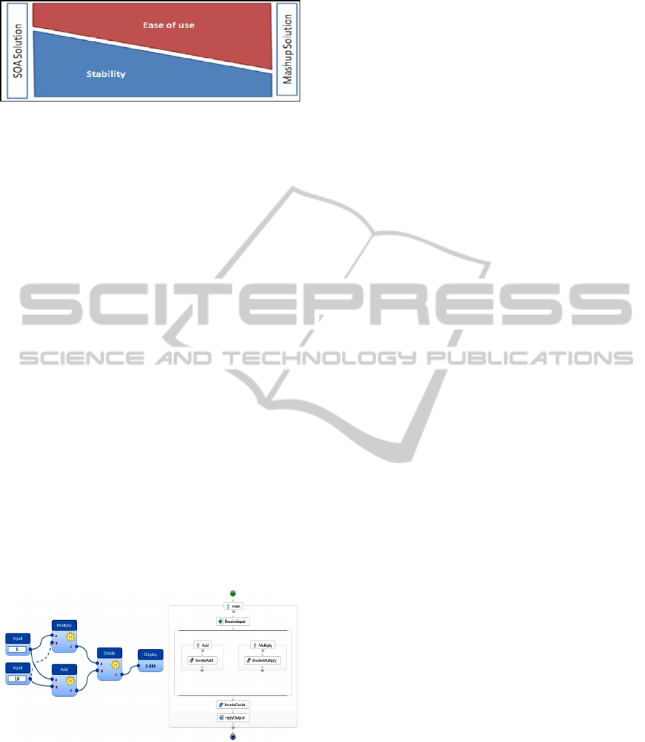
Figure 1: SOA Solution vs. Mashup solution (Amin
Anjomshoaa, 2010).
On the other hand, traditional SOA allows
experts to create robust solutions that include a high
level of complexity; end users still remaining outside
the loop of SOA development. To solve this
problem, a key would be to benefit from the
strengths of the two solutions (Mashup and SOA).
This solution would rapidly develop situational
applications using mashup technology and provide a
tool to translate the Mashup logic into the SOA logic
(ex. BPEL) that is more stable and robust. At the
end, the end user will benefit from the ease of
composition of the Mashup and from the power of
classical SOA composition engine. (Anjomshoaa
Amin and al., 2010).
Related work has focused on this problem of
conversion between Mashup solution and SOA
solution, or between Mashup logic and SOA logic.
(Anjomshoaa Amin and al., 2010) proposes a
converter Mashup-BPEL which allows transfering
the Mashup execution process located on the client
browser to a BPEL engine in the server side. This
converter uses the Mashup widgets and the
connections between them to provide the resulting
SOA service as a BPEL file deployable in any BPEL
engine. The Mashup widgets being translated into
"invoke" BPEL operations (Figure 2).
Figure 2: Simple example of a mashup (left) and its
generated BPEL process (right) (Amin Anjomshoaa,
2010).
Another way to transform a mashup into a BPEL
code is to use an intermediate language, which
facilitates the transition Mashup-BPEL. (Xiang Fu
and al., 2004) proposes a framework where BPEL
specifications are translated into an intermediate
representation using guarded automata.
In the same idea of using an intermediate
language, (Francisco Curbera and al., 2007)
proposes a minimalist language of choreography and
execution that offers a development model based on
the workflow and dedicated to server-side scripts of
all applications types that interact with client
browsers, REST resources, remote functions
available through URLs, and local functions
available through Java or JavaScript invocation
methods. The process model of this approach
implements a subset of the execution semantics of
BPEL, which is a graph containing atomic actions
(activities) and links between them (Florian
Rosenberg and al., 2009).
2 MODEL DRIVEN
DEVELOPMENT APPROACH
2.1 The Approach Description
Model Driven Development (MDD) is an emerging
technology for software development, focusing on
the role of models and enabling the automatic
creation of code through predefined model
transformations. The Model Driven Architecture
(MDA) is a variant of MDD suggested by the Object
Management Group (OMG), which provides a set of
guidelines for the structuring of specifications
expressed as models and the transformations
between these models.
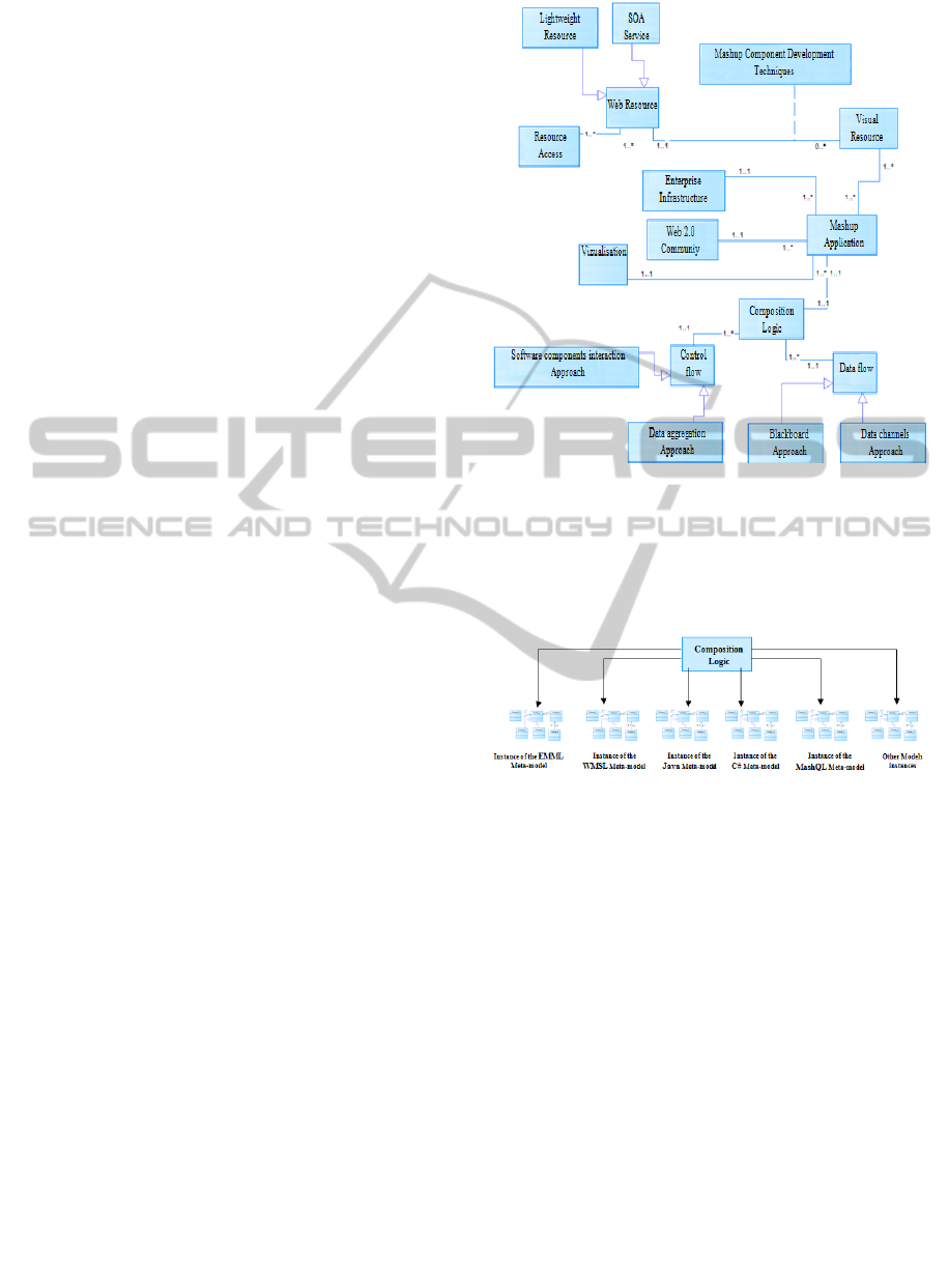
In this section, we shall present our Model
Driven Development approach whose goal is to
generate a BPEL code from end users specifications
or needs. In fact, using a Mashup platform, the end
users will graphically express their needs that consist
of services to compose, and through automatic
transformations we will generate the BPEL code
(Figure 3).
Our process involves three transformations:
Transformation 1: when the end user
expresses graphically the services that he wants
to compose and how, the Mashup platform
generates a Mashup script. Then, based on the
Mashup Meta-model, we will automatically
generate the Mashup model (UML class
diagram)
Transformation 2: this step is the most
important phase of our approach because it
represents the bridge between the Mashup
world and the SOA world. In fact, using rules
MODEL-DRIVEN APPROACH FOR USER-CENTRIC MASHUPED SOA
117
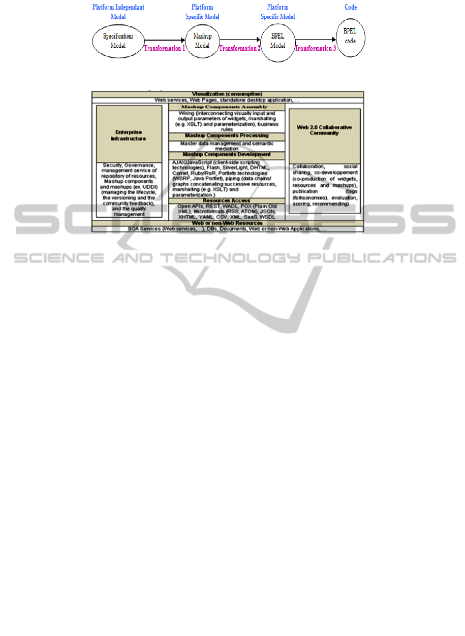
Figure 3: Model Driven Development approach for a Mashuped SOA.
Figure 4: Mashup stack.
that establish the correspondences between the
Mashup elements (Mashup Meta-model) and
the BPEL elements (BPEL Meta-model), we
will automatically generate the BPEL model
(UML class diagram)
Transformation 3: from the BEPL model
obtained from the previous transformation, we
will use a tool to generate the BPEL code.
Our approach is divided into four stages: 1) The
construction of the Mashup Meta-model, 2) The
construction of the BPEL Meta-model, 3) The
creation of a mapping layer between Mashup and
BPEL Meta-models, 4) The implementation of the
model transformation.
2.2 From PIM to Mashup-PSM
As mentioned in the last section, the end user will
expresses graphically the services that he wants to
compose and how, then the Mashup platform
generates a Mashup script. From this script file, we
will automatically generate the Mashup model based
on the Mashup Meta-model. This section is
dedicated to the construction of the Mashup Meta-
model.
The Mashup is based on a set of languages and
protocols; in (M. Benhaddi and al., 2010) we
presented a Mashup stack model that gathers the
different basic technologies, and which is inspired
by the MVC (Model-View-Controller) design
pattern. This Mashup stack contains an intermediate
layer (API) that binds a resource (service
component) considered as the Model, and its
graphical representation (GUI component)
considered as the View and manipulated by end
users.
The Mashup stack presented below includes
vertical and cross layers.
The six vertical layers stand the process of creating a
Mashup application, and the two cross layers
represent common services to all the company
services.
Concerning the “Mashup Components
Assembly” layer, Mashup technologies use different
techniques to link resources, to manipulate and
transform data. The Mashup composition techniques
also called “increase” by (Matthias Kunze, 2009)
and that specifies the control flow, consist of two
approaches:
Approach based on the Interaction of
Software Components: this approach defines
how the data of a component are connected to
the data of another, assuming that the
components are ready (Matthias Kunze, 2009)
(Jin Yu et al. , 2008). This approach generally
called Wiring and characterized by performing
aggregation after instantiation of the application,
can be divided into three styles of orchestration:
1- flows-based (sequences of tasks or
components), 2- events-based (components
behavior synchronization), or 3- layout-based
(arrangement of visual components) (Jin Yu et
al., 2008), where the event-based style is the
most used (Matthias Kunze, 2009).
ICEIS 2011 - 13th International Conference on Enterprise Information Systems
118
Approach based on the Aggregation of Data:
this approach represents the sequence of
operations or functionalities and is characterized
by execution of aggregation before launching
the application by the user. The most used
technique is pipes-and-filter (eg Yahoo Pipes)
which connects filters and applies data
processing. Query languages are also a data
agregation technique that is aligned with this
approach (Matthias Kunze, 2009).
(Nick Russell and al., 2004) divided the
workflow from the data point of view into four
groups: data visibility, data interaction, data transfer
and data-based routing. The mashup uses only the
last three groups of patterns and does not cover the
data visibility patterns group (Lai Xu and al., 2010).
Most popular operators are: union, join, sort, and
filter (Lai Xu and al., 2010) (Giusy Di Lorenzo and
al., 2009). The ''Data Interaction – Task to Task''
pattern belongs to the patterns group ''Data
Interaction' and contains the two approaches or
styles (Nick Russell and al., 2004) (Jin Yu and al.,
2008):
Blackboard Approach: this approach uses
variables (assimilated to programming
languages). Data flow is done implicitly.
Data Channels Approach: this is the most
used approach; data flow is done explicitly.
From the Mashup stack and the component
assembly layer description, we could build the
Mashup Meta-model. Figure 5 presents the UML
classes’ diagram of Mashup entities.
As we considered that the PIM is the end user
business needs in terms of services composition, the
implementation of these needs is the responsibility
of the « Mashup component assembly » layer (figure
4); consequently, the corresponding PSM will be
represented by an instance of the « Composition
Logic » entity.
In the Meta-model above, the entity called
« Composition Logic » represents the different links
used to connect the resources participating in the
Mashup application. This « Composition Logic »
entity has a control flow type and a data flow type;
however, it represents a general entity common to all
Mashup platforms, and thus the Meta-model of
figure 5 cannot represent the Meta-model of a PSM,
as the PSM is related to a specific platform. As
depicted in figure 6, many Mashup platforms exist
with a different Mashup language for each platform.
To specify the « Composition Logic » entity, a
specific Mashup platform (or language) should be
considered, which allows looking deeply
Figure 5: Mashup stack Meta-model.
at the elements that construct the Mashup
application. The « Composition Logic » entity will
be an instance of a specific platform Meta-model (a
specific Mashup composition model).
Figure 6: Multitude of models (Mashup platforms and
languages) for the Mashup composition logic.
The Mashup language that we consider is the
Enterprise Mashup Markup Language (EMML),
which we chose to use to benefit from its
advantages: it’s an XML language created in 2006
and promoted by the Open Mashup Alliance (OMA)
(OMA Faq) that has the objective of submitting the
specification to a recognized industry standards
body. EMML is free to use, including technologies
that embed or use it.
EMML is characterized by:
Control Flow Type: software components
interaction approach or wiring. In fact, the
aggregation is performed after instantiation of the
application. The style of aggregation is flow-
based (sequences of tasks or components).
Data Flow Type: blackboard approach. In fact,
EMML uses Variables to manipulate data (input,
output or intermediary data)
MODEL-DRIVEN APPROACH FOR USER-CENTRIC MASHUPED SOA
119
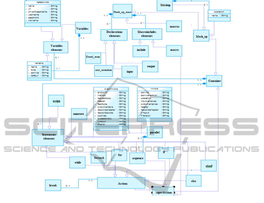
Figure 7: EMML Meta-model.
The official EMML web site (OMA EMML
documentation) lists the syntax and the different tags
used to create a Mashup script. From this
specification, we could build the EMML Meta-
model represented by the UML classes diagram in
figure 7.
We shall explain some of the Meta-model
elements. The root element of a Mashup script is
‘mashup’ element. ‘macros’ element is the root node
for macro libraries that contain macro definitions for
use in any mashup. Other EMML elements are
classified in four groups: declarations group,
macroincludes group, statements group and
variables group.
Elements of statements and variables groups are
allowed in ‘mashup’, ‘else’, ‘elseif’, ‘for’, ‘foreach’,
‘if’, ‘macro’, ‘operation’, ‘sequence’ or ‘while’
element. Elements of declarations and
macroincludes groups are allowed in ‘mashup’,
‘operation’ or ‘macros’ element. ‘invoke’ and
‘directinvoke’ elements are used to invoke a service
or a resource. Figure 7 depicts various attributes of
‘invoke’ element; for example, the name of the
service and the specific operation to invoke, the
names list of input variables and the name of the
variable that will hold the invocation result.
2.3 From Mashup-PSM to BPEL-PSM
As shown in figure 3, once we generate the Mashup
model from end users specifications, we will create
the link between the mashup application and BPEL.
This transformation establishes a bridge between the
Mashup world and the SOA world, and it is based on
the BPEL Meta-model and the mapping rules. As
output of this stage, the BPEL model will be
automatically generated, which will be used to
create the BPEL code.
2.3.1 BPEL 2.0 Meta-model
We were based on BPEL 2.0 specification (BPEL
2.0) to build the BPEL 2.0 Meta-model (figure 8).
A BPEL process contains variables declarations,
fault handlers, partner links (links to services) and
activities. Fault handlers contain ‘catch’ or
ICEIS 2011 - 13th International Conference on Enterprise Information Systems
120
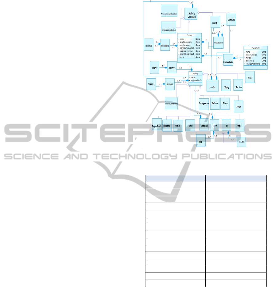
‘catchAll’ elements. A ’partnerLink’ element
characterizes the services with which the business
process interacts. Each ’partnerLink’ is
characterized by a ‘partnerLinkType’. The name of
the ’partnerLink’ is used for all service interactions.
The role of the business process is indicated by the
attribute ‘myRole’ and the role of the partner is
indicated by the attribute ‘partnerRole’. BPEL
activities are various and are allowed in ‘process’,
‘compensationHandler’ or ‘terminationHandler’
element; each activity has optional containers
<sources> and <targets>, which contain standard
elements <source> and <target> respectively, which
are used to establish synchronization relationships
through links (BPEL 2.0). The ‘invoke’ activity
allows calling Web Services, and can enclose other
activities, inlined in fault handlers.
2.3.2 Mapping of Elements
The following table depicts the correspondence
between some of the EMML and BPEL Meta-model
elements. For example, ‘mashup’ in EMML, the
element representing the root node of an EMML
script, is mapped to a BPEL Process. The mapping
also includes the generation of a number of other
BPEL elements so that the content of the output
model corresponds entirely to that of the input. In
addition to the main Process element, variables,
partnerLinks, receive, reply and activities elements
must be generated. ‘invoke’ and ‘directinvoke’
EMML elements are converted to both ‘invoke’ and
‘partnerLink’ BPEL elements. ‘input’ EMMl
element is converted to either ‘receive’, ‘pick’ or
‘onAlarm’ BPEL element. ‘output’ EMML element
is converted to ‘reply’ BPEL element. ‘parallel’,
‘assign’, ‘for’, ‘sequence’, ‘if’, ‘elseif’, ‘else’,
‘foreach’, ‘while’ and ‘variable’ elements have the
same homologous in BPEL elements. ‘break’
EMML element is converted to ‘exit’ BPEL
element.
2.3.3 Model Transformation
For the implementation of the mapping between
Mashup and BPEL elements, we need a model
transformation language that will take the Mashup
Meta-model, the BPEL Meta-model, the mapping
rules and the Mashup Model (a Mashup-SOA
application), and will generate the BPEL Model
(Figure 9). Nowadays, there are many industrial and
academic case tools supporting model
transformation (Kermeta) (QVT) (SiTra). Simple
Transformer (SiTra) (Akehurst and al., 2006) is a
model transformation minimal framework, which
Figure 8: Relevant fragment of the BPEL 2.0 Meta-model.
Table 1: Mapping of EMML and BPEL elements.
EMML BPEL
<mashup> <process>
<directinvoke>, <invoke> <invoke> + <PartnerLink>
<input>
<receive variable= >, or
<output> <reply variable= >
<parallel> <flow> + <links>
<assign> <assign>
<for> <for>
<sequence> <sequence>
<if> <if>
<elseif> <elseif>
<else> <else>
<foreach> <foreach>
<while> <while>
<variable> <variable>
<break> (only in for,
<exit>
consists of a very small and simple API that is
suitable for use by academic researchers to
experiment transformation prototypes. SiTra uses
Java for transformations specification, which avoid
the programmer from learning a new language for
the specification of transformations (Akehurst and
al., 2006). To use SiTra, the Meta-models should be
implemented in Java; this could be created manually
or using UML to Java tools.
The future implementation of our work will use
SiTra, and will experiment some Mashup scripts that
invoke Web Services.
MODEL-DRIVEN APPROACH FOR USER-CENTRIC MASHUPED SOA
121

Figure 9: Model transformation (inspired from (Hubert
Kadima, 2005)).
3 CONCLUSIONS AND FUTURE
WORK
In the last years, there was a big focus on the
convergence between the Mashup and the Service
Oriented Architecture. In fact, the Mashup has
proven to be an effective solution to promote the
SOA user-centric. However, a SOA composition
solution that will use Mashup technologies and
platforms will suffer from fragility and non stability,
unlike SOA platforms that offer robustness and
stability (ex. BPEL engine). In this paper, we
presented a Model Driven Development approach to
establish the link between a Mashup platform using
EMML (Enterprise Mashup Markup Language), and
a SOA-BPEL platform, so to convert a Mashup
EMML script that mash Web services into a BPEL
script.
The advantages of this Model Driven
Development approach compared to previously
presented approaches (Related work in
“Introduction” section) consist of:
Dynamic and Flexible Nature: all the
transformations in related work are performed
directly and statically between the Mashup and
BPEL, and any changes in the Mashup or BPEL
specification will make the framework
unusable. Our approach puts the transformation
in a high level, where any changes in the
languages specifications (EMML or BPEL) or
in the mapping rules layer will be rapidly
handled by the framework
Benefits from Model Generation: the SiTra
engine will provide a BPEL model that could be
used to generate a BPEL code (BPEL script or
file) executed by a BPEL engine, or as a part of
other transformations and other platforms.
While other approaches don’t provide
intermediaries results or offer intermediate
scripts using a language without a high
interoperability level.
Our future work consists of:
Producing Mashup-EMML Model from the
Mashup-EMML script based on the EMML
Meta-model
Implementing the Mapping Layer using
SiTra (Simple Transformer) engine and based
on the BPEL Meta-model and the mapping
rules; and experimenting Mashup scripts that
invoke Web Services
Producing BPEL Code from the generated
BPEL model
REFERENCES
Amin Anjomshoaa, Gerald Bader, A Min Tjoa (2009).
Exploiting Mashup Architecture in Business Use
Cases. Institute of Software Technology and
Interactive Systems Vienna University of Technology,
Vienna, Austria.
Boris Büchel, Till Janner, Christoph Schroth, and Volker
Hoyer (2009). Enterprise Mashup vs. Service
Composition: What fits to reach the next stage in End-
User Development?.
BPEL 2.0. OASIS. Web Services Business Process
Execution Language Version 2.0 (April 2007),
http://docs.oasis-open.org/wsbpel/2.0/OS/wsbpel-v2.0-
OS.html
LaiXu, Paul de Vrieze, Keith Phalp, Sheridan Jeary, and
Peng Liang (2010). Lightweight Process Modeling for
Virtual Enterprise Process Collaboration. IFIP
Advances in Information and Communication
Technology, 2010, Volume 336/2010, 501-508.
Florian Rosenberg, Rania Khalaf, Matthew Duftler,
Francisco Curbera and Paula Austel (2009). End-to-
end Security for Enterprise Mashups. International
Joint Conference on Service-Oriented Computing. Pp.
389 – 403. 2009.
Francisco Curbera, Matthew Duftler, Rania Khalaf and
Douglas Lovell (2007). Bite : Workflow Composition
for the Web. ICSOC, Vol. 4749Springer (2007), p. 94-
106. 2007. Gurpreet Singh Modi (2007). Service
Oriented Architecture & Web 2.0.
Giusy Di Lorenzo, Hakim Hacid, Hye-young Paik and
Boualem Benatallah. (2009). Data Integration in
Mashups. ACM SIGMOD Record , Volume 38 Issue 1.
Hubert Kadima (2005). MDA conception orientée objet
guidée par les modèles. Collection: InfoPro, Dunod
2005 - 240 pages, EAN13 : 9782100073566.
Kermeta. http://www.kermeta.org/. Last visit: 01/04/2011
M. Benhaddi, Karim Baïna, El Hassan Abdelwahed
(2010). Towards an approach for a user centric SOA.
The third International Conference on Web &
Information Technologies, April 2010.
ICEIS 2011 - 13th International Conference on Enterprise Information Systems
122

Matthias Kunze, (2009). Master’s Thesis, Business
Process Mashups An Analysis of Mashups and their
Value Proposition for Business Process Management.
Jin Yu, Boualem Benatallah, Fabio Casati and Florian
Daniel (2008). Understanding Mashup Development.
Journal IEEE Internet Computing, Volume 12 Issue 5.
Nick Russell, Arthur H.M. Ter Hofstede1, David Edmond
(2004). Workflow DataPatterns. Proceedings of the
24th International Conference on Conceptual
Modeling, pp. 353-368.
OMA Faq.: http://www.openmashup.org/faq/#4. Last
visit :01/04/2011
OMA EMML Documentation. http://www.openmashup.
org/omadocs/v1.0/index.html. Last visit: 01/04/2011
QVT. http://www.omg.org/spec/QVT/1.0/. Last visit:
01/04/2011
SiTra. http://www.cs.bham.ac.uk/~bxb/SiTra.html. Last
visit: 01/04/2011
Akehurst, D. H., Bordbar, B., Evans, M. J., Howells, W.
G. J., McDonald-Maier, K. D. (2006). SiTra: Simple
Transformations in Java. ACM/IEEE 9TH
International Conference on Model Driven
Engineering Languages and Systems, Vol. 4199, pp.
351–364 (2006)
Xiang Fu, Tevfiq Bultan and Jianwen Su (2004). Analysis
of Interacting BPEL Web Services. The 13th
international conference on World Wide Web, pp. 621-
630. 2004.
MODEL-DRIVEN APPROACH FOR USER-CENTRIC MASHUPED SOA
123
