
LEADER-FOLLOWER FORMATION CONTROL OF
NON-HOLONOMIC ROBOTS IN A REMOTE LABORATORY
Daniel Neamtu, Bart Wyns, Robin De Keyser and Clara Ionescu
Department of Electrical Energy, Systems and Automation, Ghent University, Technologiepark 913, Zwijnaarde, Belgium
Keywords:
Remote laboratory, Mobile robots, Formation control, Distance education.
Abstract:
This paper presents a remote laboratory for leader-follower formation control. The client-server architecture
of the remote laboratory is based on Matlab and JIM at the server’s side, and a Java applet created using Easy
Java Simulations at the client’s side. The implementation of the remote laboratory is described in detail and
the educational value is outlined by presenting some experimental results for formation control of two mobile
robots.
1 INTRODUCTION
Nowadays technology is evolving at an incredible
pace, providing us with possibilities that a few
decades ago were unimaginable. The development
of communication and information technologies has
completely changed the speed and penetration of in-
formation in today’s society. The teaching activity in
general has a lot to gain from the use of these new
technologies. Remote and virtual laboratories are be-
coming increasingly popular. Remote laboratories, as
compared to the classic on site instruction, present
several advantages (Dormido, 2004): i) continuous
availability of the laboratory for experimentation, ii)
there is no need for the students to travel to the univer-
sity’s site in order to perform the experiments, iii) op-
timal exploitation of the resources, iv) easy access to
different types of experiments. A very broad range of
applications can make the object of remote laborato-
ries, with some notable exceptions for example in the
chemistry field where safety requirements can pro-
hibit the use of a remote laboratory (Dormido, 2004).
In particular, remote laboratories are becoming very
popular in the field of control engineering mainly due
to the interactivity that they provide to the distance
teaching process. A few examples of remote labo-
ratories designed for performing control experiments
are given in (Vargas et al., 2009; Fabregas et al., 2009;
Farias et al., 2010), to mention just a few. These re-
mote laboratories are meant to remotely control a sin-
gle process (water tank, ball and hoop, DC motor etc.)
allowing the remote user to change the parameters of
the controller, visualizing incoming data and enable a
real-life view of the process itself.
The fields of robotics receives very much inter-
est both from the academic and industrial communi-
ties worldwide, which means that proper education in
this field becomes more and more important (Potkon-
jak et al., 2010). Building a remote laboratory for
robotic experiments is a complex task due to the in-
terdisciplinary character of this application. A few
examples of remote laboratories with the purpose to
experiment with robotic applications are presented in
(
ˇ
Safari
ˇ
c et al., 2005; Casini et al., 2009; Sayouti et al.,
2010).
In the remote laboratory presented in this paper
the final aim is to remotely control a group of mobile
robots so that they move in a leader-follower forma-
tion on a predefined trajectory.
The proposed implementation is based on Matlab
and Easy Java Simulations (EJS) (Esquembre, 2004).
EJS is a free open-source tool for easily creating sim-
ulations in Java, and targets students, teachers and re-
searchers who want to quickly create a graphical sim-
ulation. EJS was originally designed to be used by
students for interactive learning under the supervision
of educators with little programming experience. In
this implementation of a remote lab, the graphical in-
terface and the computational engine are separated.
The graphical interface was created using EJS and is
an applet that runs in the user’s browser.
Matlab is the most commonly used program in
teaching control engineering. In our remote labora-
tory implementation, the computational engine is rep-
485
Neamtu D., Wyns B., De Keyser R. and Ionescu C..
LEADER-FOLLOWER FORMATION CONTROL OF NON-HOLONOMIC ROBOTS IN A REMOTE LABORATORY.
DOI: 10.5220/0003476904850490
In Proceedings of the 3rd International Conference on Computer Supported Education (UeL-2011), pages 485-490
ISBN: 978-989-8425-50-8
Copyright
c
2011 SCITEPRESS (Science and Technology Publications, Lda.)
resented by Matlab, which runs at the server’s side.
In the next section a description of the components
that constitute the remote lab is given. In section 3 we
discuss the application of the remote lab for control-
ling a formation of robots and in the last section some
conclusions are drawn and the planned future work is
outlined.
2 COMPONENTS OF THE
REMOTE LAB
2.1 General Overview
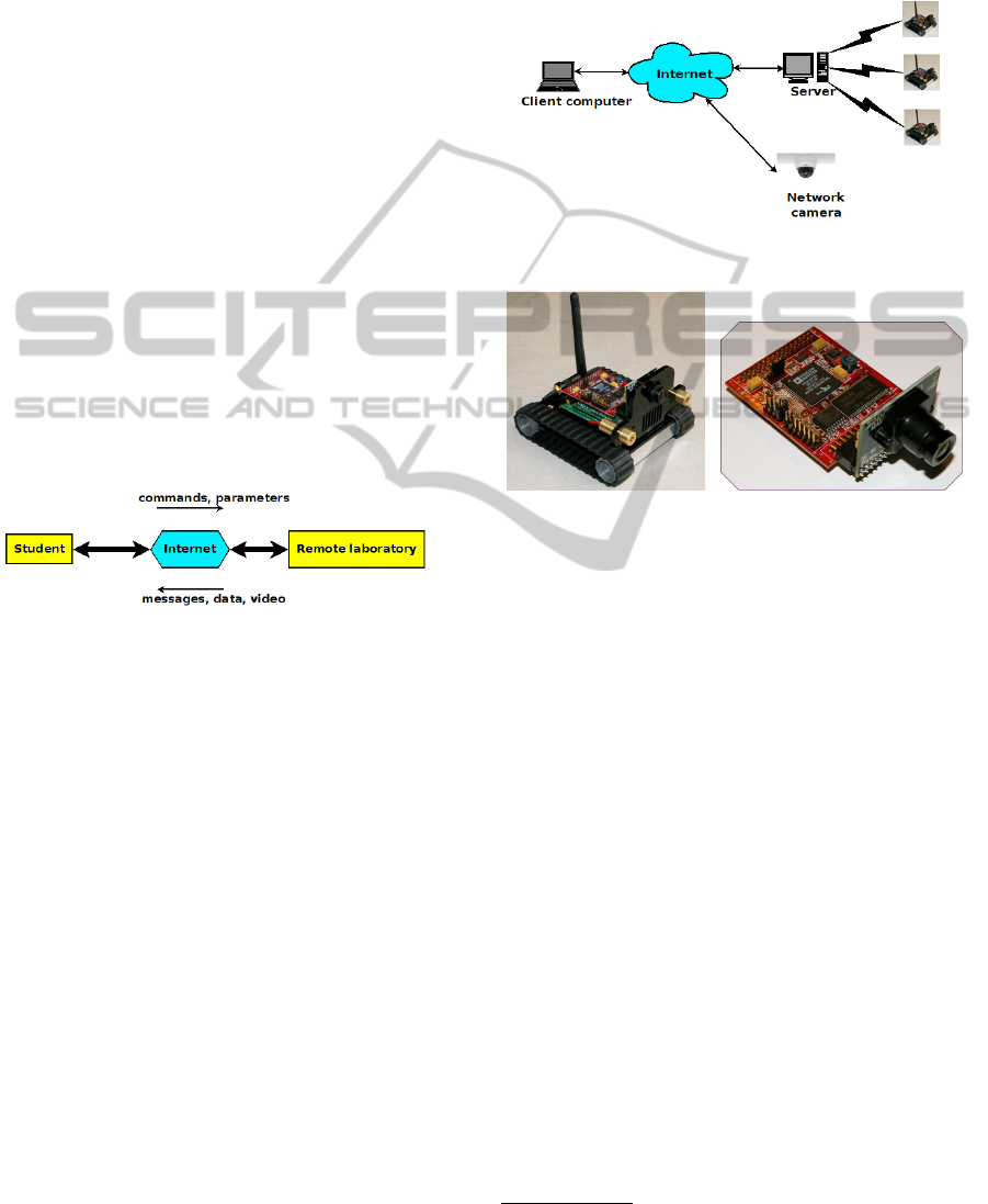
The most popular architecture used for remote lab
implementations is client-server. The client runs on
the remote user’s computer, who can access the func-
tions of the remote lab through a graphical user inter-
face. The server, which runs at the University’s site,
should be transparent for the user and insure the con-
nection with the process. The client-server connec-
tion is made using the TCP/IP protocol, over Internet,
as depicted in figure 1.
Figure 1: Client-server architecture.
Information is sent bidirectionally between the
client and the server. The client sends commands to
the server which are further sent to the process. From
the server to the client comes data acquired from the
process, real-time images of the experiment and dif-
ferent messages: the process is not connected to the
server, changes in the state of the process, alarms
when something goes wrong. Due to the high vol-
ume of data sent from the server to the client, a high
speed internet connection is necessary. The camera
has a separate internet connection so that the video is
not delayed by the data coming from the process.
2.2 Hardware
While at the client’s side a single PC with Internet
connection is sufficient, at the server’s side there are
several hardware devices, as depicted 2. In our imple-
mentation, the server itself runs on a dedicated com-
puter with permanent Internet connection. The com-
puter used is powerful enough to efficiently run all the
required software (Matlab, Apache Server, JIM) and
it has enough memory to store the data coming from
the process. It has been equipped with two network
cards: one Ethernet card used for connecting to the
Internet and a wireless card used to connect to a local
WiFi network.
Figure 2: Remote lab hardware components.
(a) Surveyor SRV-1. (b) SRV1 Blackfin camera.
Figure 3: Mobile robot used in the remote lab.
The remote user can continuously monitor the
controlled process by looking at images sent from a
network camera via a separate internet connection, as
shown in figure 2. Due to the nature of this applica-
tion, namely mobile robots in motion, the camera has
to cover a large area. For this reason, a PTZ (Pan-Tilt-
Zoom) camera was chosen such that the user is able
to move the view of the camera to the view of interest.
The process, in our case a group of non-holonomic
robots, is connected to the server using wireless
communication through a local WiFi network. The
Surveyor-SRV1
1
, shown in figure 3, is a tracked mo-
bile robot equipped with a 500 MHz microprocessor,
an on-board camera and WiFi communication. An
expansion board is available for the robot with tilt
sensors, a compass and GPS receiver. In the current
experiments, the controlled signal is the duty ratio
of the PWM signal sent to the motors and the out-
put of the process is the distance between two robots
measured using the on-board camera. The camera on
the robots supports several resolutions for the images,
however for our experiments it was chosen a resolu-
tion of 320 × 240 pixels, as a trade-off between com-
putational time and measurement accuracy. The cam-
1
http://www.surveyor.com
CSEDU 2011 - 3rd International Conference on Computer Supported Education
486
era uses YUV color representation, where Y repre-
sents the light intensity and the U and V are chroma
components.
Surveyor-SRV1 is a differentially driven robot.
The lack of wheel encoders makes the speed of the
robot run in open loop. This aspect makes the control
task more difficult particularly due to the nonlineari-
ties of the motors and the offset in angular speed be-
tween the right wheel and the left wheel. Due to this
latter aspect, lateral control of the robot is compul-
sory for maintaining the formation. The speed of the
robot is in the range 20 cm/s - 40 cm/s with a nonlin-
ear characteristic, containing a dead-zone until 20%
of the total input range.
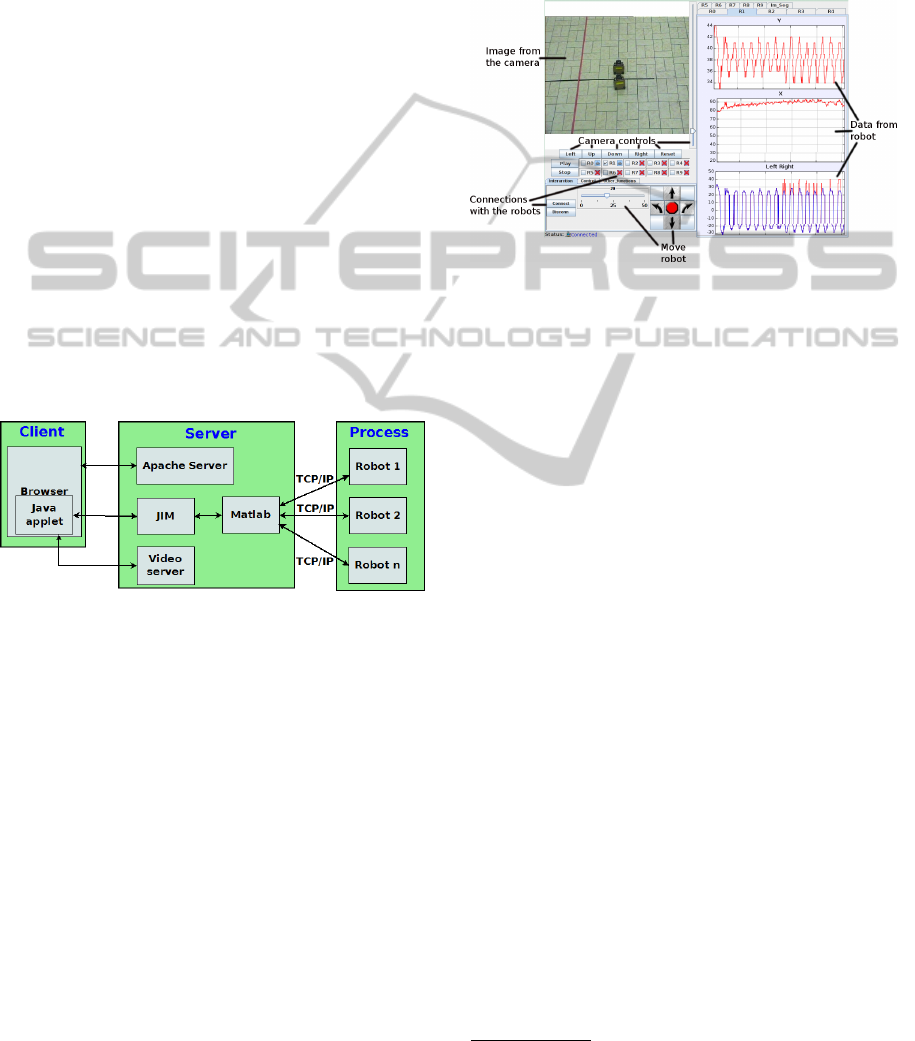
2.3 Software
The client-server software architecture of the remote
lab is shown in figure 4. The communication be-
tween the client and the server is accomplished us-
ing a TCP/IP Internet connection. On the other hand,
communication between the server PC and the mobile
robots is accomplished using TCP/IP communication
through a local network.
Figure 4: Remote lab software components.
The software requirements for the end-user are
minimal, a Java enabled web browser, which insures
the ease of use of the remote laboratory but also porta-
bility. The remote user downloads a Java applet which
displays the graphical user interface, shown in figure
5. The Java applet was generated using Easy Java
Simulations (EJS) (Esquembre, 2004). This applet
provides a user-friendly graphical user interface for
the user to access the functionalities of the remote
lab. First of all, there are live images from the ex-
periment’s site in the top left side of the GUI. The
buttons and the slider adjacent to the image of the
process enable the user to control the orientation and
the zoom of the PTZ network camera. Underneath
this, there are buttons to manually control the robots,
connect/disconnect the robots to the server, start/stop
automatic control. The right side of the GUI is for dis-
playing the data measured by the robots in the forma-
tion which consists of relative distance measurements
and the values sent to the left and right motors of the
robots. The values from the plots can be saved using
a tool provided by EJS. Also on the right side, one
of the panels is dedicated to experimenting with im-
age processing functions available on the robot: color
segmentation, edge detection and horizon detection.
Figure 5: Graphical user interface displayed in the Java ap-
plet.
A diagram of the programs that presents the soft-
ware components of the remote laboratory is shown in
figure 4. JIM
2
(Java-Internet-Matlab) server is a free
software tool written in Java that allows communica-
tion between a remote user and a Matlab server. The
connection between the remote applet and JIM is im-
plemented using a TCP/IP connection. JIM is able to
communicate with Matlab using the functions defined
in the JMatlink library (M
¨
uller and Waller, 1999).
Matlab has been chosen to be incorporated in the
structure of the remote lab since it is the tool most
widely used in the control engineering world. Matlab
provides state of the art computational capabilities.
Matlab’s core computational capabilities are extended
through several toolboxes. Information between the
firmware on the robots and the server is exchanged by
making use of the Instrument Control Toolbox
3
. Sev-
eral TCP/IP connections are made in Matlab to the
mobile robots. The commands issued by the user us-
ing the GUI are sent to Matlab which translates these
commands into characters that can be processed by
the firmware on the robots. The role of Matlab is also
to receive the data coming from the robots and make it
available to the remote applet through the transparent
link provided by JIM server.
The camera is running a web server that can re-
ceive commands from a remote user. The user can
control the PTZ network camera from the GUI. These
actions are translated into HTTP queries which are
sent to the web server on the camera. The HTTP
2
http://lab.dia.uned.es/rmatlab/
3
http://www.mathworks.com/products/instrument/
LEADER-FOLLOWER FORMATION CONTROL OF NON-HOLONOMIC ROBOTS IN A REMOTE LABORATORY
487
queries are translated into actions for the servos of the
camera – pan and tilt – and for the lens – zoom action.
The firmware running on the robots is open-source
and can be easily modified using C programming
language. Some of the functionalities available are:
real-time timing, image acquisition, image process-
ing – using color segmentation and edge detection,
integer number computations, floating point compu-
tations using a library, control of the motors using
PWM signals etc. The tracking algorithm which con-
sists of image processing for estimating the distance
and computing the control value to be sent to the mo-
tors takes 70 ms. This value represents the sampling
time of the process. All the robots have a static IP as-
signed so that they are easy to identify in the network.
3 CONTROL EXPERIMENT
A leader-follower formation assumes that there exists
one or more leaders in the formation and the other
robots, the followers, copy the actions of the leader. In
this work, a single leader, column formation is used.
This formation is similar to the cars on one lane of a
highway, where cars follow each others and maintain
a safe distance. Similar implementations of formation
control of mobile robots are described in (Anderson
et al., 2006) and (Klan
ˇ
car et al., 2009).
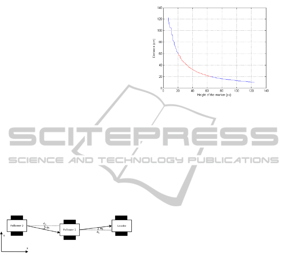
Figure 6: Leader-follower formation.
In a leader-follower formation, the followers
should maintain a constant distance and a constant
relative angle with respect to the robot in front. For
the experiments, we set the distance reference to d =
30 cm and the angle reference to θ = 0
◦
(see figure 6).
Relative distance and relative angle are measured
using image processing on images taken by the on-
board camera. In order to distinguish the robots from
the environment, a rectangular red marker with the di-
mensions 8.1cm × 3.6cm was attached to the back of
the robots. The follower robot captures frames from
the on-board camera and using adaptive color seg-
mentation, the red marker is isolated in the image.
The projection of the marker in the plane of the
image is computed in pixels. The values of interest
are the height of the blob and the position of blob on
the horizontal axis. A relationship between the height
Figure 7: Measured distance - height characteristic.
of the blob and the real distance was determined ex-
perimentally, the result is shown in figure 7. The re-
gion of the characteristic depicted with red is almost
linear, between 20 cm and 60 cm. On this region a 3
rd
order polynomial was fitted, with as input the height
of the marker in the image measured in pixels, and
output the distance d between the robots measured in
centimeters:
d = −0.0004 · h
3
y
+ 0.0717 · h
2
y
−
−4.53 · h
y
+ 125.16 (1)
The accuracy of this measurement is between 1-
4 cm, depending on the focus of the camera and the
distance between the robots.
the position of the marker on the horizontal axis
of the image is considered in order to estimate the rel-
ative orientation between the robots. Taking into con-
sideration that the resolution of the image is 320 ×
240, a 0
◦
relative orientation is achieved when the
center of the marker in the image, relative to the hori-
zontal axis, is equal to 160 pixels. This measurement
cannot exceed the field of view of the camera which is
60
◦
in total. This measurement procedure is affected
by errors when the marker is only partially visible in
the image, either due to changing light or if the ori-
entation angle between the robots exceeds the field of
view of the follower’s camera.
The control algorithm is implemented on the mi-
croprocessor of each robot, thus we have a decentral-
ized formation control. So far, no direct communi-
cation among robots is possible. Communication can
be implemented using a central communication point
through the server, which would have the task to for-
ward messages from one robot to the other.
The goal is to have a good longitudinal control on
the robots so that the leader-follower formation is pre-
served. On the other hand, lateral control is also nec-
essary for maintaining the formation and the marker
CSEDU 2011 - 3rd International Conference on Computer Supported Education
488
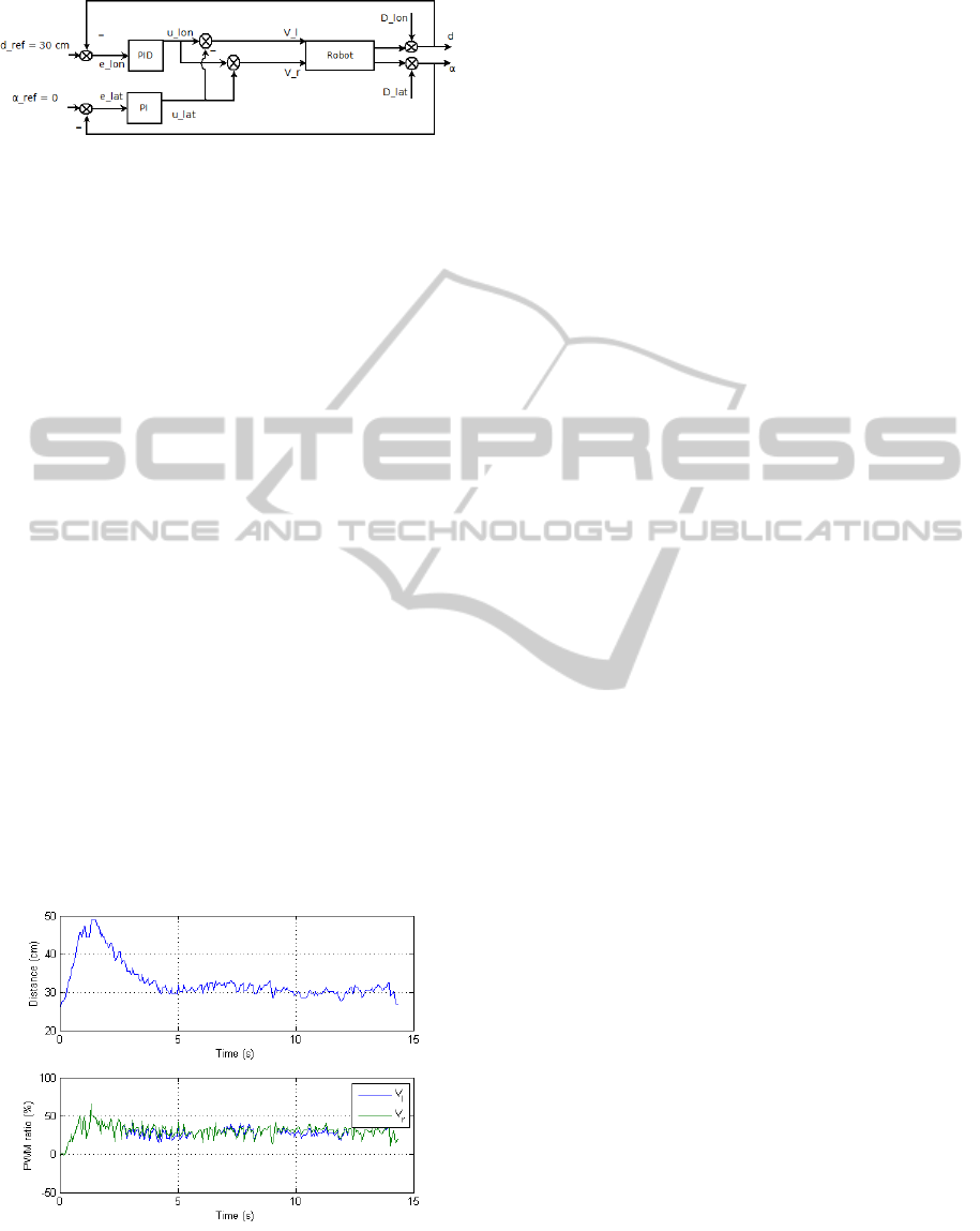
Figure 8: Control structure used for tracking.
in the field of view of the follower. A drawback of the
Surveyor SRV-1 is the lack of wheel encoders so all
the robots present an offset in the rotational speed of
the left and right tracks. This offset means that for the
same PWM values sent to both the left and right side,
the robot will not drive straight as it should. In order
to solve this issue, a second controller was added for
the lateral dynamics.
The structure of the controller is presented in fig-
ure 8. The longitudinal controller is a PID. The refer-
ence distance is set constant d
re f
= 30 cm. The mea-
sured distance is continuously disturbed by the move-
ment of the robot in front. This longitudinal distur-
bance is denoted D
lon
in figure 8. Due to the offset
of the motors and the movement of the leader, there
is a disturbance D
lat
on the lateral dynamics of the
system. A PI controller receives the error between
the reference angle α
re f
= 0 and the measured angle
α. The commands to the motors of the robots are ob-
tained using the longitudinal and lateral control, ac-
cording to the formula:
V
l
= u
lon
− u
lat
, V
r
= u
lon
+ u
lat
(2)
where V
l
and V
r
are the PWM duty cycles sent to the
left and right motors of the differentially driven robot;
u
lon
and u
lat
are the outputs of the longitudinal PID
controller and of the lateral PI controller.
Figure 9: Tracking result for one leader and one follower.
The proposed control strategy shows good per-
formance. In figure 9 it is presented the result for
tracking of one robot using the proposed control strat-
egy. The formation of two robots was running along a
straight line, with the leader following a colored line
on the floor. After a transient of 4 s in the beginning,
the follower keeps a constant distance with respect to
the leader in front.
In order to decrease the floor space necessary for
the remote laboratory and to make it easier for the re-
mote user to supervise the experiment, an ellipsoidal
colored track of length 225 cm and at each end two
semicircles with diameters of 176 cm was put on the
floor. The leader of the platoon follows the colored
track while the follower robots maintain the line for-
mation. The task of the followers it is more difficult
when the path is not straight. Turning of the robots
can cause the formation to be broken or can induce
oscillations in the lateral control that will propagate
in the entire formation.
4 CONCLUDING REMARKS
This paper presented a remote lab for robotic applica-
tions. The remote laboratory was implemented using
Matlab and EJS connection supported by JIM Server.
The educational value of this remote lab comes from
the fact that students will be able to experiment with
this setup and tune the PID control.
This paper shows once again the added value that
new technologies bring to the teaching process. Ex-
perimentation on the developed laboratory provides
a fundamental educational feature: students can ob-
serve on-the-fly the resulting dynamics and be aware
of some physical phenomena that are less obvious,
difficult to explain from just a theoretical point of
view.
Planned future work includes decreasing the min-
imum speed of the robots by changing the mechani-
cal reduction of the motors, so that they are able to
maintain the formation in a larger number on the el-
lipsoidal track on the floor. There are also plans of en-
hancing the functionality of the remote laboratory by
adding more options to the graphical user interface:
controller parameter changing, select between mul-
tiple controllers, perform identification experiments,
auto-tunning.
ACKNOWLEDGEMENTS
The authors would like to thank to KCO for funding
this project.
Also, the authors express their gratitude to Enersto
LEADER-FOLLOWER FORMATION CONTROL OF NON-HOLONOMIC ROBOTS IN A REMOTE LABORATORY
489

Fabregas Acosta from the UNED University, Madrid,
Spain.
REFERENCES
Anderson, J., Lee, D., Schoenberger, R., and Tippetts, B.
(2006). Using real-time vision to control a convoy of
semi-autonomous unmanned vehicle. In AUVSIs Un-
manned Systems North America, online proceedings.
Casini, M., Garulli, A., Giannitrapani, A., and Vicino., A.
(2009). A matlab-based remote lab for multi-robot ex-
periments. In Proceedings of the 8th IFAC Symposium
on Advances in Control Education, Kumamoto, Japan.
Dormido, S. (2004). Control learning: present and future.
Annual Reviews in Control, 28:115–136.
Esquembre, F. (2004). Easy Java Simulations: a software
tool to create scientific simulations in Java. Computer
Physics Communications, 156:199 – 204.
Fabregas, E., Duro, N., Dormido, R., Dormido-Canto, S.,
Vargas, H., and Dormido, S. (2009). Virtual and re-
mote experimentation with the ball and hoop system.
In IEEE Conference on Emerging Technologies and
Factory Automation ETFA’ 2009, Palma de Mallorca,
Spain.
Farias, G., Keyser, R. D., Dormido, S., and Esquembre, F.
(2010). Developing networked control labs: a Matlab
and Easy Java Simulations approach. IEEE Transac-
tions on Industrial Electronics, 57(10):3266–3275.
Klan
ˇ
car, G., Matko, D., and Bla
ˇ
zi
ˇ
c, S. (2009). Wheeled mo-
bile robots control in a linear platoon. J Intell Robot
Syst, 54:709–731.
M
¨
uller, S. and Waller, H. (1999). Efficient integration of
real-time hardware and Web based services into Mat-
lab. In Proceedings of 11th European Simulation Sym-
posium.
Potkonjak, V., Vukobratovic, M., Jovanovic, K., and
Medenica, M. (2010). Virtual mechatronic/robotic
laboratory - a step further in distance learning. Com-
puters & Education, 55(2):465 – 475.
Sayouti, A., Lebbat, A., Medromi, H., and Aniba, F. Q.
(2010). Remote laboratory for teaching mobile sys-
tems. (IJCNS) International Journal of Computer and
Network Security, 2:28–32.
Vargas, H., Sanchez-Moreno, J., Dormido, S., Salzmann,
C., Gillet, D., and Esquembre, F. (2009). Web-enabled
remote scientific environments. Computing in Science
& Engineering, 11(3):36–46.
ˇ
Safari
ˇ
c, R., Trunti
ˇ
c, M., and Pa
ˇ
cnic, G. (2005). Control
and robotics remote laboratory for engineering educa-
tion. iJOE International Journal on Online Engineer-
ing, 1(1):1–8.
CSEDU 2011 - 3rd International Conference on Computer Supported Education
490
