
A THIRD GENERATION MICRO-VEHICLE TESTBED
FOR COOPERATIVE CONTROL AND SENSING STRATEGIES
Maximillian Gonzalez
Department of Engineering, Harvey Mudd College, CA 91711, Claremont, U.S.A.
Xinheng Huang, David S. Hermina Martinez
Department of Electrical Engineering, University of California, CA 90059, Los Angeles, U.S.A.
Chung H. Hsieh, Yuan R. Huang
Anteros Labs, Inc, CA 90505, Torrance, U.S.A.
Benjamin Irvine, Martin B. Short, Andrea L. Bertozzi
Department of Mathematics, University of California, CA 90059, Los Angeles, U.S.A.
Keywords:
Robotics testbed, Mobile robots, Cooperative motion, Barrier avoidance, Target detection.
Abstract:
This paper describes the third generation of an economical cooperative control testbed, last described in (Le-
ung et al., 2007). The new testbed vehicles are improved with powerful on-board computing, upgraded and
expanded on-board sensing, and enhanced wireless communication, while maintaining economic feasibility
and scale. The new hardware allows for increased autonomy of each vehicle and for the implementation of
new, more advanced algorithms that rely on increased computational capability. We demonstrate practical
use of the testbed for algorithm validation by implementing both previous and new cooperative steering and
barrier avoidance algorithms.
1 INTRODUCTION
The motivations behind the development of algo-
rithms for multi-agent cooperative behavior have
roots in a variety of disciplines. For example, un-
manned aircraft reduce the risks put on human lives
in hazardous environments and combat zones, and
greater developmentof autonomousmotor vehicle be-
havior could greatly reduce the number of traffic ac-
cidents, of which the vast majority are caused by hu-
man error. In addition, increases in mechanical au-
tonomy have already reduced the need for many hu-
man operators in industry and commerce, and further
work in this field can only accelerate their efficiency.
The need to understand these and similar problems
(Michael et al., 2011; Bhattacharya et al., 2010) has
therefore resulted in the construction of many labo-
ratory testbeds (Jin et al., 2004; Turgut et al., 2007;
Cruz et al., 2007; Punpaisarn and Sujitjorn, 2008;
McLain and Beard, 2004; Azarnasab and Hu, 2007;
Sibley et al., 2002).
Laboratory testing of cooperative control algo-
rithms is important to the development of the field
because it brings real-world sensor issues, communi-
cation issues, and movement issues to the forefront of
the research. One of the biggest challenges for lab-
oratory testbeds, however, is lack of adequate space.
Rarely do users have access to a dedicated area large
enough to allow for the testing of multi-vehicle path
planning algorithms with vehicles that possess the ca-
pacity for on-board computing. Typically, such a ve-
hicle footprint would be at least the size of a laptop
computer, necessitating a testbed arena on the order
of 10 m across or more for meaningful experiments.
To avoid such space constraints, we have focused
on the development of a micro-sized testbed that al-
lows for testing of complex algorithms with vehi-
cles that have a footprint smaller than a typical mo-
14
Gonzalez M., Huang X., S. Hermina Martinez D., H. Hsieh C., R. Huang Y., Irvine B., B. Short M. and L. Bertozzi A..
A THIRD GENERATION MICRO-VEHICLE TESTBED FOR COOPERATIVE CONTROL AND SENSING STRATEGIES.
DOI: 10.5220/0003449400140020
In Proceedings of the 8th International Conference on Informatics in Control, Automation and Robotics (ICINCO-2011), pages 14-20
ISBN: 978-989-8425-75-1
Copyright
c
2011 SCITEPRESS (Science and Technology Publications, Lda.)
bile phone. This requires the design and implemen-
tation of custom vehicles as well as careful thought
into how algorithms are developed and managed. In
prior work (Hsieh et al., 2006; Leung et al., 2007),
we developed a robust testbed based on modified toy
cars that was successful in testing cooperative control
algorithms, but also suffered from some major dis-
advantages. For example, the first generation testbed
(Hsieh et al., 2006) required a centralized computer
to perform all algorithm processing and send com-
mands to the micro-cars, which lacked any form of
on-board computing or sensors. The second genera-
tion (Leung et al., 2007) added IR range sensors and
very modest on-board computing to the microcars,
but they were still reliant on a processing computer
for any advanced algorithms. This paper describes a
third generation vehicle that is completely customized
with vastly increased computational power, allowing
not only for on-board algorithm processing but also
for realtime user interaction via a remote terminal, as
well as an array of sensors and enhanced communi-
cation capabilities. All this is done while still main-
taining the compact footprint of prior work, avoiding
space constraint issues.
The remainder of the paper is organized as fol-
lows: Section 2 describes the setup of the testbed and
the new generation micro-car hardware and software,
Section 3 presents some of the experiments that have
been implemented on the testbed, and Section 4 out-
lines future testbed goals and conclusions.
2 TESTBED SETUP AND
HARDWARE
The UCLA Applied Mathematics Laboratory Testbed
(AMLT) is divided into three subsystems: an
overhead-camera and PC tracking system, a re-
mote terminal PC, and the micro-car robotic vehicles
(Fig. 1).
Physically, the testbed is a 1.5 m x 2.0 m rect-
angular area in which the micro-cars operate. The
area itself is made of black asphalt felt paper with a
white boundary, providing a uniform, non-reflective
background for imaging purposes. The cars’ posi-
tions are tracked by 2 overhead Imaging Source DMK
21F04 1/4 Monochrome CCD cameras with a resolu-
tion of 640 x 480 pixels. They have a frame rate of
30 fps and are connected to an image processing PC
via firewire cable. The cars are identified using an
OpenCV contour searching function that recognizes
black and white ID tags, or “hats” , that are fixed atop
each micro-car, giving each car’s current position and
orientation (Hsieh et al., 2006; Leung et al., 2007).
This information is then broadcast through a serial ra-
dio module to be received by the cars on the testbed,
for use in control algorithms. This mimics the func-
tionality of a GPS unit that may be present in more
advanced vehicles in the field.
The cars are given commands and can relay status
information by communicating via a separate serial
radio with an interface PC that serves primarily as a
remote terminal for the cars. The ability to broadcast
messages to the interface PC for display proves to be
a very useful debugging tool.
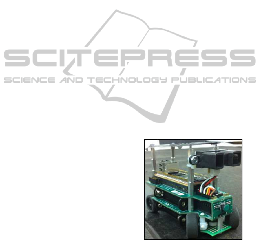
2.1 Vehicle Hardware
The third generation micro-cars (model ALMC-100,
see Fig. 2 for a hardware schematic) are purpose built
from the ground up, in contrast to previous genera-
tion vehicles that were modified off-the-shelf toy cars.
The ALMC-100 is designed to mimic many of the
features one would expect to find in a full sized au-
tonomous vehicle, in a compact package. The vehi-
cle measures approximately 8 cm (wheelbase) x 5 cm
(width); the height varies from 5.8 cm to 8 cm de-
pending on configuration. The ALMC-100 is a rear
wheel drive, front steering car with a maximum speed
of 20 cm/s and maximum turning angle of ±18
◦
.
Power comes from four AAA batteries with approxi-
mately 3.8 W, yielding a run time of greater than 30
minutes.
Figure 1: One of the ALMC-100 micro-cars.
The ALMC-100 features two processing units on
individual printed circuit boards, which are stacked
atop each other. The lower “chassis” board is the base
of the vehicle where the drive train is bolted in addi-
tion to the electronics. The chassis board contains a
50MHz ARM Cortex-M3 processor with 8KB SRAM
A THIRD GENERATION MICRO-VEHICLE TESTBED FOR COOPERATIVE CONTROL AND SENSING
STRATEGIES
15
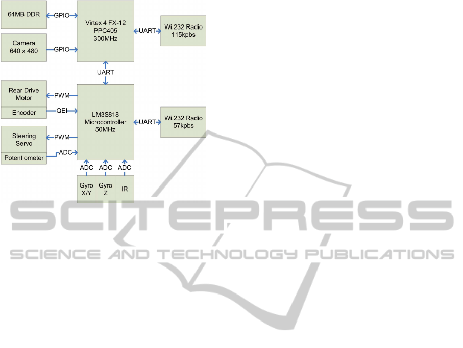
Figure 2: A block diagram of the ALMC-100 micro-car
hardware.
and 64KB flash memory. A 1KB EEPROM is also in-
cluded to store unique, non-volatile information such
as vehicle identification number and motor control
gains and offsets. The chassis board also houses two
gyroscopes for 3-axis measurements, a 0.45
◦
optical
encoder used for velocity estimation, and is attached
to either a long-range or short-range IR module; the
long range sensors can detect objects in the 10 cm -
140 cm range, while the short range sensors can only
detect from 10 cm - 80 cm.
The upper “processing” board contains an off-the-
shelf Xilinx Virtex-4 FX12 FPGA Mini-Module. Cur-
rently, the FPGA is configured to embed a 300MHz
PowerPC405 processor plus a number of peripheral
interfaces. The interfaces allow the PPC405 to access
64MB of DDR SDRAM and 4MB of flash memory
among other peripherals.
The wireless communication system consists of
two Wi.232 radio modules, one on each board, ca-
pable of transmitting and receiving at 11520 bps. The
wireless module on the chassis board is configured
to 57600 bps and receives only information from the
overhead tracking system, mimicking GPS. The wire-
less module on the processing board is configured to
115200 bps and is intended for inter-vehicle commu-
nication and for access of the vehicle via the remote
terminal. The two radios operate on different frequen-
cies to avoid interference.
The driving factor behind the use of two process-
ing units is to segregate motion control and path plan-
ning. The motion control is accomplished on the
chassis board, which maintains its control loop at
1000 Hz while sampling the various sensors at 500
Hz. The chassis processor extracts the vehicle’s own
position from the overhead tracking system’s broad-
cast sent at 30 Hz. The vehicle’s position and other
vehicle and sensor states are relayed to the process-
ing board also at 30 Hz over the universal asyn-
chronous receiver/transmitter (UART) connecting the
two boards. Thanks to the powerful processing avail-
able to the upper board, the cars can perform all re-
quired path planning themselves; in previous versions
of the AMLT, vehicles relied on a desktop computer
to perform all such calculations and relay instructions
to the cars.
2.2 Vehicle Software
Each vehicle runs two separate controlling programs.
The chassis board controller is based on FreeRTOS
(Real Time Engineers Ltd., 2011), a realtime operat-
ing system that can run multiple tasks at up to 1000
Hz, and is designed to provide two main functionali-
ties: control the vehicle’s motion by providing PWM
signals for the drive motor and the servo, and supply
sensory data and system information for the process-
ing board. At the center of the chassis board controller
is a path-generation task that calculates target veloc-
ities at 100 Hz and generates PWM signals at 50 Hz
that feed the servo. Based on the target velocities, a
velocity-controltask generates a 1000Hz PWM signal
to control the drive motor. The controller is also de-
signed to recognize a set of serial commands, thus al-
lowing the processing board to control high-level mo-
tion and access data.
The processing board boasts much deeper mem-
ory space and faster processing speed, and can thus
support more complex programs that can feature user-
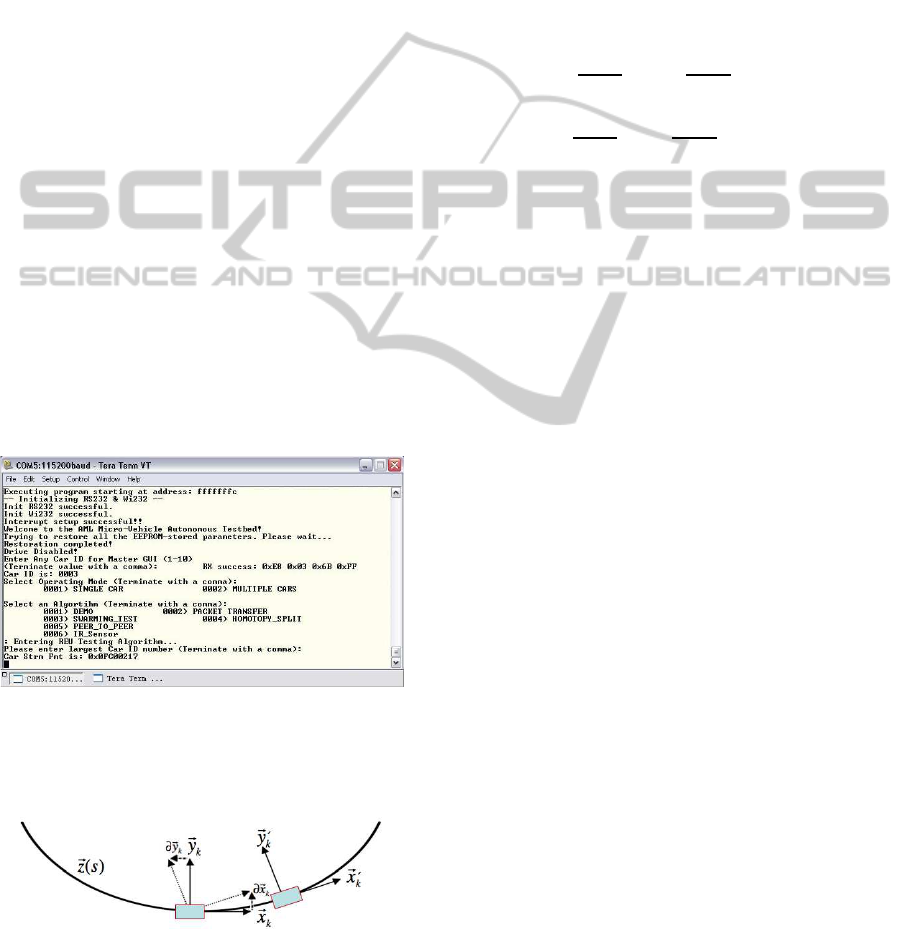
friendly interfaces and large data-sets. Currently, this
controller serves as a remote terminal interface (Her-
mina Martinez, 2010), an example of which is shown
in Fig. 3. In order to interface with the user, the
micro-car transmits messages to the interface PC, via
its upper serial radio. If many cars are in use at once,
only one car, chosen by the user, broadcasts the termi-
nal messages. The user interacts with the micro-cars
through the interface PC’s keyboard. These inputs are
transmitted to the micro-cars, which then execute the
chosen algorithms. The interface is composed of two
modes: a single car mode for demonstrating basic op-
eration of the vehicles, and a multiple car mode to
implement cooperative algorithms.
ICINCO 2011 - 8th International Conference on Informatics in Control, Automation and Robotics
16
3 TESTBED EXPERIMENTS
The motion of the cars is modeled based on a Frenet-
Serret framework as in the second-generation testbed
(Morgan and Schwartz, 2005). Each car k has its own
coordinate frame relative to its heading, with x
k
be-
ing the unit vector oriented in the direction the car’s
motion and y
k
being the unit vector oriented perpen-
dicular to x
k
(Fig. 4). The car’s motion can then be
described with the following equations:
˙z
k
= x
k
, ˙x
k
= vu
k
y
k
, ˙y
k
= −vu
k
x
k
, (1)
where z
k
(s) is the arclength parametrized path of the
car with respect to a fixed coordinate frame, the scalar
u
k
is the curvature of the path at a specific point, and v
is the (typically constant) speed of the vehicle. Thus,
the path of each car can be determined simply by
specifying its curvature over time. To convert from
curvature u
k
to the desired turning angle φ
k
of the ve-
hicle’s wheels, we use the equation
φ
k
= tan
−1
(u
k
L
car
) , (2)
where L
car
is the car length of 8 cm. If |φ
k
| > 18
◦
,
the maximum turning angle that the servos can turn,
|φ
k
| is rounded down to the maximum. This limits the
minimum turning diameter to approximately 50 cm,
a notable constraint for the testbed, which is 1.5 m x
2.0 m.
Figure 3: A typical screenshot of the remote terminal on the
interface PC, showing several menus in its structure. Near
the bottom, the multiple car mode menu is shown with sev-
eral of the algorithm selections visible.
Figure 4: Diagram of the coordinate frame of a micro-car
moving along a parametrized path z(s).
3.1 Cooperative Motion Algorithms
From Morgan & Schwartz’s model for swarming
(Morgan and Schwartz, 2005), the curvature for each
car k is calculated as
u
k
=
∑
j6=k
u
jk
, (3)
where j cycles through the indices of all the other cars
on the testbed. For simple swarming, the following
equation for u
jk
is used:
u
jk
= −η
r
jk
kr
jk
k
· x
k
r
jk
kr
jk
k
· y
k
−
α
"
1−
r
0
kr
jk
k
2
#
r
jk
kr
jk
k
· y
k
+ µx
j
· y
k
, (4)
where r
jk
is the vector from car j to car k, r
0
is the
desired distance between cars for the swarm, and α,
η, and µ are weighting parameters for three separate
aspects of the desired motion. The term with coeffi-
cient η works to turn each car perpendicular to r
jk
;
the term with coefficient α turns the cars toward each
other if they are further than r
0
apart, and turns them
away from each other if they are closer than r
0
; and
the term with coefficient µ orients the cars toward a
common heading. By varying the three weights of
these terms and introducing slight modifications, dif-
ferent cooperativemotion can be achieved, such as the
circle-tracking, leader following, and homotopy con-
trol laws described in (Leung et al., 2007).
The summation in Eq. 3 is typically over all cars,
leading to global coupling. However, such coupling
should rarely be expected in real-world scenarios,
where each vehicle may only know its own position
and perhaps the positions of a few other nearby ve-
hicles. Therefore, in addition to global coupling,
we have also tested a form of daisy-chain coupling
whereby each car k is only coupled to the two cars
with indices j = k± 1, as illustrated in Fig. 5. The im-
plementation of this daisy-chain algorithm on larger
swarms has yielded promising results on the testbed.
Although each car is only aware of two others, the
swarm operates as a whole because of the iterative
coupling utilized by the daisy-chain system. The per-
formance of the swarm is somewhat dependent on ini-
tial placement of the micro-cars, however, a behavior
noted in similar systems (Marshall et al., 2005). If the
cars are ordered by ID, the daisy chain swarm per-
forms excellently; the cars rarely collide and find a
common heading quickly. However,if they are placed
in a random order, collisions may occur as the cars
are not necessarily aware of their closest neighbors,
which may no longer be the cars they are coupled to.
A THIRD GENERATION MICRO-VEHICLE TESTBED FOR COOPERATIVE CONTROL AND SENSING
STRATEGIES
17
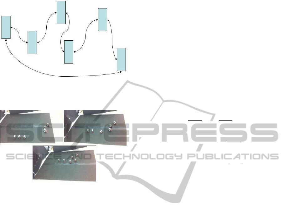
Figure 5: Diagram of daisy-chain coupling with the cars
iteratively connected. End conditions were used to create a
closed loop.
Figure 6: Three frames of an experimental run using daisy-
chain coupling. The cars are originally separated in two
groups (top left). During the run, the cars regroup (top right)
and find a common orientation before exiting the testbed
(bottom).
This especially occurs if the cars are initially placed
in close proximity to each other, typically less than
approximately two car lengths. However, if groups
of cars are initially separated by distances larger than
this, they are usually able to regroup and find a com-
mon heading with very few collisions, as shown in
Fig. 6.
In addition to the fixed daisy-chain based on car
index numbers described above, we have also imple-
mented an algorithm that creates a closed daisy-chain
upon algorithm startup, based on initial vehicle loca-
tions. For each car k, the algorithm determines the
two cars “connected” to k in the following way:
• Partition all cars into two groups – those to the left
of k (subset L
k
) and those to the right of k (subset
R
k
), based upon the position and orientation of k
and the positions of all other cars.
• If R
k
is not empty, partner one is the physically
closest member of R
k
. Otherwise, partner one is
the physically furthest member of L
k
.
• If L
k
is not empty, partner two is the physically
closest member of L
k
. Otherwise, partner two is
the physically furthest member of R
k
.
This algorithm allows the cars to create a daisy-chain
that operates well under a broader range of initial con-
ditions, since partners are chosen at startup in such a
way as to generally minimize the initial distances be-
tween partners while maintaining the closed loop that
allows the chain to function as a whole.
3.2 Barrier Avoidance and Target
Seeking
A control law similar to Eq. 4 can be used to avoid
barriers and seek a target. This is accomplished with
the equation
u
jk
= γ
"
1−
r
0
kr
tk
k
2
#
r
tk
kr
tk
k
· y
k
−
β sign
"
∑
b
C(r
bk
, 0, ω)
r
bk
kr
bk
k
· y
k
#
"
∑
b
C(r
bk
, 0, ω)
r
bk
kr
bk
k
· x
k
#
, (5)
where
C(r, q, ω) =
1 krk < ω
q otherwise
, (6)
r
tk
is the vector from car k to the target, r
bk
is the
vector from car k to the barrier b, and γ and β are
the weights assigned to the target seeking and barrier
avoidance behaviors, respectively.
Eq. 5 is dependent on the car’s knowledge of the
position of the target and of all barriers within a cer-
tain distance ω of itself. This has been implemented
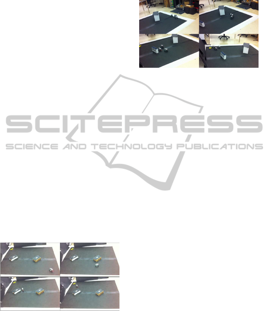
on our testbed in two ways. The first uses a hard-
coded target position and makes use of hats sitting on
the barriers. The tracking cameras pick up the bar-
rier locations and relay the information to the target-
seeking car, which then weaves its way through the
obstacles to its goal. Several photos of such an exper-
iment are shown in Fig. 7.
Ideally, though, the cars would not rely on the
tracking computer to provide them with information
on the location of barriers, but would instead use their
IR sensors to detect barriers on the fly and adjust their
movement accordingly; our second implementation
of barrier avoidance does just this. It again uses a
hard-coded target position, but now uses the IR sen-
sor readings of the cars to estimate values for r
bk
.
Since the sensors only work over a limited range, this
naturally incorporates a term such asC(r
bk
, 0, ω) into
the behavior. One disadvantage of this method is that
only barriers nearly directly ahead of the car can be
ICINCO 2011 - 8th International Conference on Informatics in Control, Automation and Robotics
18
sensed, so that cars may occasionally turn into nearby
barriers that lie at their sides. We find, though, that the
relatively slow motion and large turning radius of the
cars minimizes these issues, and that swarms of cars
employing this algorithm, in conjunction with Eq. 4,
typically navigate the barriers successfully, as show
in Fig. 8
4 FUTURE WORK AND
CONCLUSIONS
Though the third generation of the AMLT has already
surpassed previous versions in terms of successfully
performed experiments, there are still many aspects
of the new hardware that have not yet been utilized.
Foremost amongst these is the potential for a true
peer-to-peer communication network for the vehicles.
Creating such a network would allow for the imple-
mentation of many advanced algorithms. For exam-
ple, it would allow for the vehicles in our daisy-chain
setup to determine their nearest neighbors in realtime,
decreasing the chances of collisions occurring.
Another avenue of exploration is greater usage of
the many on-board sensors. The optical encoder and
gyroscopes could allow each car to estimate its own
position over time with less reliance on the tracking
computer, assuming the car’s initial coordinates are
known. This would mimic the intermittent GPS out-
ages expected in field vehicles, and give methods for
dealing with them. Also, the on-board camera could
perhaps be used in conjunction with the IR sensor for
enhanced barrier detection, or possibly target detec-
tion when the location of the target is unknown.
Figure 7: Four frames of an experimental run of tracking
camera-assisted barrier avoidance, with the yellow object
in the top left of each frame as the target. The frames are
ordered from left to right, top to bottom. The car detects the
first barrier in the second frame and begins to avoid it. It
continues toward the target and avoids the second barrier in
frame three and reaches the target in frame four.
Figure 8: Four frames of an experimental run of IR sensor
barrier avoidance, with the yellow object near the top left of
frames three and four as the target. The frames are ordered
from left to right, top to bottom. The cars detect the first
barrier in the second frame and avoid it. They continue to-
ward the target and avoid the second barrier in frame three
and reach the target in frame four.
ACKNOWLEDGEMENTS
This paper is supported by ARO MURI grant 50363-
MA-MUR and NSF grants DMS-0914856, DMS-
0907931, DMS-0601395, and EFRI-1024765.
REFERENCES
Azarnasab, E. and Hu, X. (2007). An integrated multi-robot
test bed to support incremental simulation-based de-
sign. In Proceedings of the IEEE International Con-
ference on System of Systems Engineering.
Bhattacharya, S., Michael, N., and Kumar, V. (2010). Dis-
tributed coverage and exploration in unknown non-
convex environments. In 10th International Sympo-
sium on Distributed Autonomous Robots. Springer.
Cruz, D., McClintock, J., Perteet, B., Orqueda, O. A. A.,
Cao, Y., and Fierro, R. (2007). Decentralized cooper-
ative control - a multivehicle platform for research in
networked embedded systems. Control Systems Mag-
azine, IEEE, 27(3):58 – 78.
Hermina Martinez, D. S. (2010). Integration of 3rd gener-
ation vehicles to the applied mathematics laboratory
autonomous micro-vehicle testbed. Master’s thesis,
Department of Electrical Engineering, University of
California, Los Angeles.
Hsieh, C. H., Chuang, Y. L., Huang, Y., Leung, K. K.,
Bertozzi, A. L., and Frazzoli, E. (2006). An eco-
nomical micro-car testbed for validation of coopera-
tive control strategies. In Proceedings of the American
Control Conference, pages 1446–1451.
Jin, Z., Waydo, S., Wildanger, E. B., Lammers, M.,
Scholze, H., Foley, P., Held, D., and Murray, R. M.
(2004). MVWT-II: the second generation Caltech
Multi-Vehicle Wireless Testbed. In Proceedings of the
American Control Conference, pages 5321 – 5326.
A THIRD GENERATION MICRO-VEHICLE TESTBED FOR COOPERATIVE CONTROL AND SENSING
STRATEGIES
19

Leung, K. K., Hsieh, C. H., Huang, Y. R., Joshi, A.,
Voroninski, V., and Bertozzi, A. L. (2007). A sec-
ond generation micro-vehicle testbed for cooperative
control and sensing strategies. In Proceedings of the
American Control Conference, pages 1900–1907.
Marshall, J. A., Fung, T., Broucke, M. E., D’Eleuterio, G.
M. T., and Francis, B. A. (2005). Experimental valida-
tion of multi-vehicle coordination strategies. In Pro-
ceedings of the American Control Conference, pages
1091–1095.
McLain, T. and Beard, R. W. (2004). Unmanned air vehicle
testbed for cooperative control experiments. In Pro-
ceedings of the American Control Conference, pages
5327 – 5331.
Michael, N., Fink, J., and Kumar, V. (2011). Cooperative
manipulation and transportation with aerial robots.
Autonomous Robots, 30(1):73–86.
Morgan, D. S. and Schwartz, I. B. (2005). Dynamic coordi-
nated control laws in multiple agent models. Physics
Letters A, 340:121–131.
Punpaisarn, S. and Sujitjorn, S. (2008). SUT-CARG car-
like robots: their electronics and control architec-
ture. WSEAS Transactions on Circuits and Systems,
7(6):579–589.
Real Time Engineers Ltd. (2011). FreeRTOS-A Free RTOS
for ARM7, ARM9, Cortex-M3, MSP430, MicroB-
laze, AVR, x86, PIC32, PIC24, dsPIC, H8S, HCS12
and 8051. http://www.freertos.org.
Sibley, G., Rahimi, M., and Sukhatme, G. (2002). Robo-
mote: A tiny mobile robot platform for large-scale
sensor networks. In Proceedings of the 2002 IEEE In-
ternational Conference on Robotics and Automation.
Turgut, A. E., Gokc¸e, F., Celikkanat, H., Bayındır, L., and
Sahin, E. (2007). Kobot: A mobile robot designed
specifically for swarm robotics research. Technical
report, Department of Computer Engineering, Middle
East Technical University, Ankara, Turkey.
ICINCO 2011 - 8th International Conference on Informatics in Control, Automation and Robotics
20
