
FEASIBLE DYNAMIC RECONFIGURATIONS OF PETRI NETS
Application to a Production System
Mohamed Khalgui
1,2
, Olfa Mosbahi
1,2
1
ICTICA, Ariana, Tunisia
Jiafeng Zhang
2
, Zhiwu Li
2
2
Xidian University, Xi’an, Shaanxi, China
Atef Gharbi
University of Carthage, Tunis, Tunisia
Keywords:
Petri Net, Control System, Reconfiguration, Model Checking, Computation Tree Logic.
Abstract:
The paper deals with dynamic automatic reconfigurations of Control Systems to be classically modelled by
Petri nets. Three different forms can be applied at run-time to reconfigure such systems: Addition/Removal of
places, Addition/Removal/Update of transitions or finally the simple change of the initial marking. We define
three formal modules allowing reconfigurations of the system’s Petri nets: changer places to dynamically
change places of the model, changer transitions to dynamically reconfigure transitions, and changer marking
to modify the initial markings of places. To guarantee a correct behavior of this architecture according to
user requirements, we apply a model checking by using the useful tool SESA for the verification of CTL-
based properties of the proposed modules and also of the system. The paper is applied to a Real Benchmark
Production System.
1 INTRODUCTION
The new generation of control systems is addressing
new criteria as flexibility and agility. To reduce their
cost, these systems should be changed and adapted to
their environment without disturbances. Several in-
teresting academic and industrial research works have
been made in recent years to develop reconfigurable
control systems (Gehin and Staroswiecki, 2008). We
distinguish in these works two reconfiguration poli-
cies: static and dynamic reconfigurations such that
static reconfigurations are applied off-line to apply
changes before the system’s cold start (Angelov et al.,
2005), whereas dynamic reconfigurations are dynam-
ically applied at run-time. Two cases exist in the
last policy: manual reconfigurations applied by users
(Rooker et al., 2007) and automatic reconfigurations
applied by Intelligent Agents (Al-Safi and Vyatkin,
2007). We are interested in this paper in automatic
reconfigurations of control systems that we model by
the formal formalism Net Condition/Event Systems
(NCES) which is an extension of Petri nets (Rausch
and Hanisch, 1995). In NCES, places classically cor-
respond to control actions to be done by the control
system. To move from a place to another, a transi-
tion should be fired. There are several conditions to
be fulfilled to enable a transition to fire. First of all,
all pre-places have to be marked with at least one to-
ken. In addition, it may have incoming condition arcs
from places and event arcs from other transitions. A
transition is enabled by condition signals if all source
places of the condition signals are marked by at least
one token. The other type of influence on the firing
can be described by event signals which come to the
transition from some other transitions. We mean in
this research paper by an automatic reconfiguration
any addition-removal of places, transitions, condition
signals or event signals to/from the NCES specify-
ing the control system, and any change in the ini-
tial marking. To handle automatic reconfigurations,
we define three NCES-based modules such that the
first allows the addition-removal of places in/from the
system’s NCES, the second allows addition-removal
of transitions, event signals, condition signals in/from
the system, and finally the third allows modifications
of the initial marking. To guarantee a correct be-
105
Khalgui M., Mosbahi O., Zhang J., Li Z. and Gharbi A..
FEASIBLE DYNAMIC RECONFIGURATIONS OF PETRI NETS - Application to a Production System.
DOI: 10.5220/0003448901050110
In Proceedings of the 6th International Conference on Software and Database Technologies (ICSOFT-2011), pages 105-110
ISBN: 978-989-8425-77-5
Copyright
c
2011 SCITEPRESS (Science and Technology Publications, Lda.)

havior of the whole system after any reconfigura-
tion scenario, we apply a model checking by using
the tool SESA that allows verifications of properties
of system’s NCES and also of the proposed mod-
ules (Rausch and Hanisch, 1995). We use the tem-
poral logic ”‘Computation Tree Logic” (denoted by
CTL) to specify these properties (Roch, 2000a; Roch,
2000b). The paper is applied to a Benchmark Pro-
duction System EnAS available in the Research Lab-
oratory of Prof.Dr. Hans-Michael Hanisch at Martin
Luther University in Germany. We describe this sys-
tem in (Mohamed Khalgui, 2008).
We present a quick state of the art on model check-
ers in the next section, before specify reconfigurable
control systems in Section 3, and propose the recon-
figuration modules in Section 4. We apply in Section
5 the model checking of the whole architecture, and
conclude the paper in Section 6.
2 STATE OF THE ART: MODEL
CHECKERS
Finite state machines (abbr. FSM) are widely used for
the modelling of control flow in embedded systems
and are amenable to formal analysis like model check-
ing (Clarke et al., 2000; Clarke and Kurshan, 1996;
Holzmann, 1997; Vardi and Wolper, 1994; Ma and
Tsai, 2008). Two kinds of computational tools have
been developed last years for model checking: tools
like KRONOS (Daws et al., 1996), UPPAAL (Am-
nell et al., 2001), HyTech (Henzinger et al., 1997) and
SESA (SESA, 2008) which compute sets of reachable
states exactly and effectively, whereas emerging tools
like CHECKMATE (Chutinan and Krogh, 1999), d/dt
(Asarin et al., 2000) and level-sets (Mitchell and
Tomlin, 2000) methods approximate sets of reach-
able states. Several research works have been pro-
posed in recent years to control the verification com-
plexity by applying hierarchical model checking for
complex embedded systems. The authors propose in
(Alur and Yannakakis, 1998) an approach for verifica-
tions of hierarchical (i.e. nested) finite state machines
whose states themselves can be other machines. The
straightforward way to analyze a hierarchical machine
is to flatten and apply a model checking tool on the
resulting ordinary FSM, but the authors show in this
interesting research work that this flattening can be
avoided by developing useful algorithms for verifica-
tions of hierarchical machines.
3 SPECIFICATION OF
RECONFIGURABLE CONTROL
SYSTEMS
Reconfiguration means qualitative changes in struc-
tures, functionalities, and algorithms of control sys-
tems as responses to qualitative changes of goals of
controls, of controlled systems, or of environments
the systems behaves within. This could be caused
by (partial) failures, breakdowns, or even by human
interventions. Let us denote by Sys the reconfig-
urable control system to be modelled by Net Con-
dition/Event Systems Σ(Sys) that specify all possi-
ble behaviors of the system to be applied after well-
defined reconfigurations.
Σ(Sys) = {PTN, CN, WCN, I, WI, EN, em}
Where,
PT N = {P
Σ(Sys)
, T
Σ(Sys)
, F
Σ(Sys)
, W
Σ(Sys)
}
We mean by a reconfiguration scenario of Σ(Sys)
(i) any addition/removal of places, (ii) any addi-
tion/removal of transitions, (iii) any addition/removal
of condition-event arcs, (iv) any update of marking.
The system can be specified by different sub-NCES
defining different possible behaviors to be followed
under well-defined conditions. Let ξ(Sys) be a sub-
NCES that models Sys after a well-defined automatic
reconfiguration scenario.
ξ(Sys) = {PT N
ξ(Sys)
, CN
ξ(Sys)
, WCN, I, W I, EN
ξ(Sys)
,
em}
Where,
PT N
ξ(Sys)
= {P
ξ(Sys)
, T
ξ(Sys)
, F
ξ(Sys)
, W
ξ(Sys)
}
Such that,
• P
ξ(Sys)
⊆ P
Σ(Sys)
,
• T
ξ(Sys)
⊆ T
Σ(Sys)
,
• F
ξ(Sys)
⊆ F
Σ(Sys)
.
If ξ(Sys) specifies the system when a particular re-
configuration scenario is applied, the places of P
ξ(Sys)
(resp, transitions of T
ξ(Sys)
and arcs of F
ξ(Sys)
) be-
come the only able places of P
Σ(Sys)
to be activated
(resp, only able transitions of T
Σ(Sys)
and able arcs of
F
Σ(Sys)
). The rest of places, transitions and arcs be-
come disable.
Running Example.
In the Benchmark Production System EnAS, only
four sub-NCES are possible to specify its behavior
when well-defined reconfiguration scenarios are au-
tomatically applied at run-time (Figure 1).
• Let ξ
1
(Sys) be the first sub-NCES that specifies
EnAS when the Second Production Policy is ap-
plied such that (EnAS model1 in Figure 1):
ICSOFT 2011 - 6th International Conference on Software and Data Technologies
106
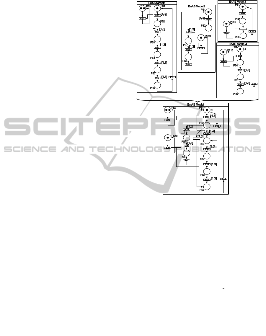
P
ξ
1
(Sys)
= {PS1, PS2, PS3, PS4, PS5, PS6, PS9}
The place PS1 corresponds to the displacement of
an empty tin on the belt to the first Jack station
where a piece is put (e.g. the place PS2). The
tin is displaced thereafter (e.g. place PS3) to the
second Jack station where a second piece is put
before it is closed with a cup (e.g. place PS4). The
closed tin is displaced thereafter on the belt (e.g.
place PS5) to the second Gripper station G2 for an
evacuation to the second storing station St2. We
note finally that the place PS9 defines the number
of pieces (e.g. two pieces) to be put in the tin
when the Second Production Policy is applied.
• Let ξ
2
(Sys) be the second sub-NCES that speci-
fies EnAS when the First Production Policy is ap-
plied such that (EnAS model2 in Figure 1):
P
ξ
2
(Sys)
= {PS1, PS2, PS7, PS8, PS10}
The place PS7 corresponds to the displacement
of a tin containing a piece and closed with a cup
from the first Jack station to the first Gripper sta-
tion (e.g. place PS8). We note finally that the
place PS10 defines the number of pieces (e.g. one
piece) to be put in the tin when the First Produc-
tion Policy is applied.
• Let ξ
3
(Sys) be the third sub-NCES that specifies
EnAS when the second Jack station is broken such
that (EnAS model3 in Figure 1):
P
ξ
3
(Sys)
= {PS1, PS2, PS6, PS10}
The place PS2 corresponds to the placement of a
piece in a tin to be closed with a cup in the first
Jack station. The place PS 6 corresponds to the re-
moval from the belt to the second Storing Station
St2.
• Let ξ
4
(Sys) be the fourth sub-NCES that specifies
EnAS when the first Jack station is broken such
that (EnAS model4 in Figure 1):
P
ξ
4
(Sys)
= {PS1, PS3, PS4, PS5, PS6, PS10}
The places PS1 and PS3 correspond to the dis-
placement of an empty tin on the belt to the sec-
ond Jack station where a piece and a cup are put
(e.g. the place PS4). The closed tin is displaced
thereafter on the belt (e.g. place PS5) to the sec-
ond Gripper station G2 for an evacuation to the
second storing station St2 (e.g. PS6). We note
finally that the place PS10 defines the number of
pieces (e.g. only one piece) to be put in the tin
when the first Jack station is broken.
Figure 1: Specification of the Reconfigurable EnAS with
NCES.
4 RECONFIGURATION OF NET
CONDITION/EVENT SYSTEMS
To dynamically reconfigure the NCES Σ(Sys), we de-
fine nested state machines where states correspond
to other state machines. Each state machine forms
a module allowing reconfigurations of the system.
Three types of modules are distinguished in this pa-
per: the first module called changer places is mod-
elled by a NECS to be denoted by CP in which each
place p = recon f igure(ξ(Sys)) corresponds to a sub-
set P
ξ(Sys)
⊆ P
Σ(Sys)
. Therefore each transition in this
state machine corresponds to the addition-removal of
places in/from the system’s specification. For each
place p of CP, we define a particular module called
changer transitions and modelled by NCES to be de-
noted by CT (CT = transition(p)) in which each place
corresponds to a particular composition of places in
the system’s specification ξ(Sys). Each transition
corresponds therefore to the addition or removal of
transitions, event or condition arcs in ξ(Sys) (p =
FEASIBLE DYNAMIC RECONFIGURATIONS OF PETRI NETS - Application to a Production System
107

recon f igure(ξ(Sys))). We define finally a third par-
ticular type of modules called changer marking mod-
elled by a NCES to be denoted by CM in which each
place corresponds to a particular marking of Σ(Sys).
A place of CM corresponds to one or more places of
a module changer transitions or the whole module
changer places.
CP =
{PT N
CP
, CN
CP
, WCN
CP
, I
CP
, W I
CP
, EN
CP
, em
CP
}
PT N
CP
= {P
CP
, T
CP
, F
CP
, W
CP
}
CT =
{PT N
CT
, CN
CT
, WCN
CT
, I
CT
, W I
CT
, EN
CT
, em
CT
}
PT N
CT
= {P
CT
, T
CT
, F
CT
, W
CT
}
CM =
{PT N
CM
, CN
CM
, WCN
CM
, I
CM
, W I
CM
, EN
CM
, em
CM
}
PT N
CM
= {P
CM
, T
CM
, F
CM
, W
CM
}
We denote by ∆(CT ) (resp. ∆(CM)) the set of C T
(resp. CM) modules. The whole control system is
characterized by different behaviors such that each
one should be executed after a well-defined recon-
figuration scenario. Each scenario to be denoted by
(p, q, k) (p ∈ P
CP
, q ∈ P
CT
= transition(p) such that
CT ∈ ∆(CT ), and k ∈ P
CM
such that CM ∈ ∆(CM))
is executed when the corresponding place p is ac-
tive in CP, the place q is active in CT and finally
the place k is active in the module CM. We denote
by Behavior
p,q,k
(Sys) the sub-NCES of Σ(Sys) that
can implement Sys when the reconfiguration scenario
(p, q, k) should be automatically applied. We syn-
chronize the modules CP, CT and CM by event sig-
nals as follows: For each scenario (p, q, k),
• ∀t1 ∈
•
p and t2 ∈
•
q, ∃ev1 ∈ (t1, t2),
• ∀t2 ∈
•
q and t3 ∈
•
k, ∃ev2 ∈ (t2, t3).
We synchronize in addition the reconfiguration
modules and the specification Σ(Sys) of the system
Sys by event signals as follows: For each scenario
(p, q, k) such that Behavior
p,q,k
(Sys) = ξ(Sys),
• ∀t1 ∈
•
q, ∃t2 ∈ T
ξ(Sys)
such that ∃ev1 = (t1, t2),
• ∀t3 ∈
•
k, ∃t4 ∈ T
ξ(Sys)
such that ∃ev2 = (t3, t4).
The events ev1 and ev2 allow applications of re-
configuration scenarios to activate places and/or tran-
sitions and/or arcs and/or to change marking in the
NCES ξ(Sys) ∈ Σ(Sys).
Running Example.
According to Figure 2, the module
Changer places CP1 is composed of two places
P1 and P2 that respectively define the Second and
the First Production Policy. The transitions tr1 and
tr2 define in this case the addition and removal
Controller of Transitions: CT1
Controller of Places: CP1
Controller of Transitions: CT2
Controller of
Marking: CM1
Controller of
Marking: CM2
EnAS Model
P4
P1 P2
P3
P5
P6
P7
P8
P9 P10
P11
P12 P13
PS1
PS2
PS3
PS4
PS5
PS6
PS7
PS8
PS9
PS10
tr1tr2
tr3
tr4
tr5tr6
tr7tr8
tr9
tr10
tr11
tr12
tr13
tr14
tr15tr16
tr17
tr18tr19
tr20
tr21
tr22
tr23
tr24
tr25
tr26
tr27
tr28
tr29
tr30
tr31
tr32
tr33
tr34
[1,3]
[1,3]
[1,3]
[1,3]
[1,3]
[1,3]
[1,3]
[1,3]
Figure 2: NCES-based Modules for Automatic Reconfigu-
rations of EnAS.
of places in the system’s specification. When the
transition tr1 is fired, we disable the places PS3,
PS4, PS5, PS6 and PS9, and we activate the places
PS7, PS8 and PS10. We associate for the place P1
the NCES CT 1 and for the place P2 the NCES C T 2.
The place P4 of the module CT 1 corresponds to
the execution of the second production policy when
PS1, PS2, PS3, PS 4, PS5, PS6, PS9 are specifying
EnAS. The place P5 specifies the system when
the second Jack station is broken. The place P6
corresponds to any problem in the first Jack station.
The place P7 is reached when the first and the second
Jack stations are broken. The place P9 of the module
CT 2 defines an execution scenario of EnAS when the
first Jack and Gripper stations are used to produce
pieces. We note in addition that the places P12 is
active from the module CT 1 when we put two pieces
in the tin, whereas the place P13 is active when only
one piece is put in the tin (e.g. it is activated by CT 2).
5 MODEL CHECKING OF
RECONFIGURABLE
PETRI-NETS
Once the reconfigurable Petri nets are well-modelled,
the next step to be addressed is their verification in or-
der to guarantee a correct behavior of the system after
any reconfiguration scenario. We use in this research
work the model checker SESA to verify CTL-based
properties defined in user requirements. This tool al-
lows the verification of any reactions of reconfigura-
tion modules as well as their synchronization with the
ICSOFT 2011 - 6th International Conference on Software and Data Technologies
108
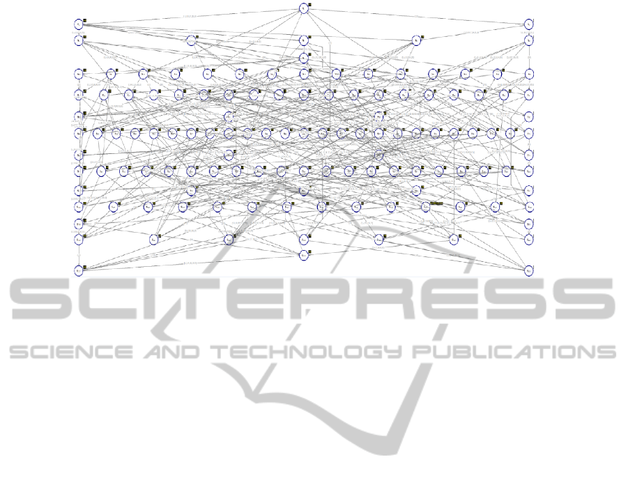
Figure 3: Reachability Graph of the Reconfigurable Architecture.
system’s NCES that should be checked too. We show
in Figure 3 a reachability graph generated by SESA
for the verification of NCES depicted in Figure 2.
Running Example.
In the system EnAS, we check functional proper-
ties of the state machines that encode the agent and
the system’s NCES. We have to check in particular
that whenever the transition tr1 is fired, then the place
PS7 should be reached:
AGAtr1XPS 7
This formula is proven to be True by applying this
tool. Indeed, when conditions are satisfied to apply
the Second Production Policy, the state PS7 should
be reached. We have also to check that whenever the
transition tr5 is fired to apply the second policy, the
place PS5 should be applied to bring the tin from the
first and second Jack stations to the second Gripper
station:
AGAtr5XPS 5
This formula is proven to be True. We check also
the correct behavior of the system EnAS when the
Second Production Policy is applied by verifying the
following formula:
AGAtr29XAFEtr30X AFEtr31X AFEtr32XT RUE
Indeed, whenever the belt is activated to transport
a piece to the first Jack station, it is activated again to
transport the piece to the second Jack station before
reaching the second Gripper station. This formula is
proven to be True by SESA. When the Second Pro-
duction Policy is applied, we check also if the evac-
uation of a closed tin from the belt can be done in
4 time units. The following formula is proven to be
False by SESA:
EF[3, 4]PS 6
The following formula is proven to be True:
AF[5, 6]PS6
Indeed the state PS6 (e.g. evacuation from the
belt) should be reached 5 time units at least after the
activation of the place PS1.
6 CONCLUSIONS
The paper deals with automatic reconfigurations to
dynamically change the behaviors of control systems:
it is a New Challenge in Industry. We specify this
behavior by Net Condition/Event Systems which is
an extension of Petri nets. A reconfiguration scenario
is any addition-removal-update of places, transitions,
event signals, condition signals, or just the modifica-
tion of the initial marking. We define formal modules
allowing reconfigurations of NCES, where the first
module deals with places, the second with transitions
and the third with the marking. We apply a model
checking for the verification of CTL-based properties
in order to guarantee a safe bevahior of this recon-
figurable architecture. In future works, we plan the
NCES-based modelling and CTL-based verification
of communication protocols that allow safe coordi-
nations inside distributed control systems.
ACKNOWLEDGEMENTS
This work was supported in part by the Natural Sci-
ence Foundation of China under Grant 60773001, the
FEASIBLE DYNAMIC RECONFIGURATIONS OF PETRI NETS - Application to a Production System
109

Fundamental Research Funds for the Central Uni-
versities under Grant No. 72103326, the National
Research Foundation for the Doctoral Program of
Higher Education, the Ministry of Education, P. R.
China, under Grant No. 20090203110009, ”863”
High-tech Research and Development Program of
China under Grant No 2008AA04Z109, the Research
Fellowship for International Young Scientists, Na-
tional Natural Science Foundation of China, and
Alexander von Humboldt Foundation.
REFERENCES
Al-Safi, Y. and Vyatkin, V. (2007). An ontology-based
reconfiguration agent for intelligent mechatronic sys-
tems. In Third International Conference on Indus-
trial Applications of Holonic and Multi-Agent Sys-
tems. Springer-Verlag.
Alur, R. and Yannakakis, M. (1998). Model checking of
hierarchical state machines. In Sixth ACM Symposium
on the Foundations of Software Engineering, pp. 175-
188.
Amnell, T., Behrmann, G., Bengtsson, J., D’Argenio, P. R.,
David, A., Fehnker, A., Hune, T., Jeannet, B., Larsen,
K. G., Mller, M. O., Pettersson, P., Weise, C., and
Yi, W. (2001). Uppaal - Now, Next, and Future. In
Proceedings of Modelling and Verification of Paral-
lel Processes (MOVEP’2k), France. LNCS Tutorial
2067, pages 100-125, F. Cassez, C. Jard, B. Rozoy,
and M. Ryan (Eds.).
Angelov, C., Sierszecki, K., and Marian, N. (2005). De-
sign models for reusable and reconfigurable state ma-
chines. In L.T. Yang and All (Eds): EUC 2005, LNCS
3824, pp:152-163. International Federation for Infor-
mation Processing.
Asarin, E., Bournez, O., Dang, T., and Maler, O. (2000).
Approximate reachability analysis of piecewise-linear
dynamical systems. In Hybrid Systems: Computation
and Control, Third International Workshop, LNCS.
Chutinan, A. and Krogh, B. K. (1999). Verification of
polyhedral-invariant hybrid automata using polygonal
flow pipe approximations. In Hybrid Systems: Com-
putation and Control, Second International Work-
shop, LNCS.
Clarke, E., Grumberg, O., and Peled, D. (2000). Model
checking. In MIT Press.
Clarke, E. and Kurshan, R. (1996). Computer-aided verifi-
cation. In IEEE Spectrum, 33(6).
Daws, C., Olivero, A., Tripakis, S., and Yovine, S. (1996).
The tool kronos. In Hybrid Systems III, Verification
and Control, LNCS 1066, Springer-Verlag.
Gehin, A.-L. and Staroswiecki, M. (2008). Reconfiguration
analysis using generic component models. In IEEE
Transactions on Systems, Machine and Cybernetics,
Vol.38, N.3.
Henzinger, T. A., Ho, P., and Womg-Toi, H. (1997). Hytech:
the next generation. In TACAS95: Tools and Algo-
rithms for the Construction and Analysis of Systems,
LNCS.
Holzmann, G. (1997). The model checker spin. In IEEE
Transactions on Software Engineering, 23(5).
Ma, L. and Tsai, J. (2008). Formal modeling and analysis of
a secure mobile-agent system. In IEEE Transactions
on Systems, Machine and Cybernetics, Vol.38, N.1.
Mitchell, I. and Tomlin, C. (2000). Level set methods for
computation in hybrid systems. In Hybrid Systems:
Computation and Control, Third International Work-
shop, LNCS.
Mohamed Khalgui, Martin Hirsch, D. M. H.-M. H. (2008).
Reconfiguration of embedded systems. In Interna-
tional Conference on Informatics in Control, Automa-
tion and Robotics ICINCO-ICSO, pages: 157-162.
Rausch, M. and Hanisch, H.-M. (1995). Net condition/event
systems with multiple condition outputs. In Sympo-
sium on Emerging Technologies and Factory Automa-
tion. Vol.1, pp.592-600.
Roch, S. (2000a). Extended computation tree logic. In Pro-
ceedings of the CESP2000 Workshop, number 140in
Informatik Berichte, pages225-234, Germany.
Roch, S. (2000b). Extended computation tree logic: Im-
plementation and application. In Proceedings of the
AWPN2000 Workshop, Germany.
Rooker, M. N., Sunder, C., Strasser, T., Zoitl, A., Hum-
mer, O., and Ebenhofer, G. (2007). Zero downtime re-
configuration of distributed automation systems : The
εcedac approach. In Third International Conference
on Industrial Applications of Holonic and Multi-Agent
Systems. Springer-Verlag.
SESA (2008). Signal/net system analyzer.
In http://www.ece.auckland.ac.nz/ vy-
atkin/tools/modelchekers.html.
Vardi, M. and Wolper, P. (1994). Reasoning about infi-
nite computations. In Information and Computation,
115(1).
ICSOFT 2011 - 6th International Conference on Software and Data Technologies
110
